2. Technical Specification
The manufacturer reserves himself the right to make the manual's content or welder's function
change without any preliminary notification of the users.
www.fubag.ru
Omperator's anual
--3
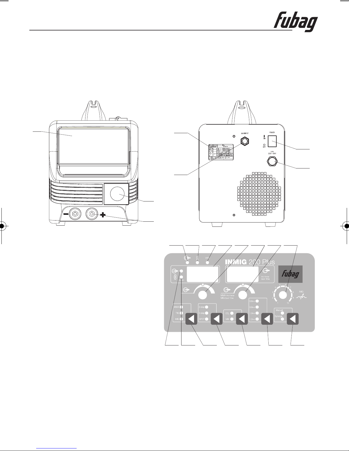
Description INMIG 200 Plus
Input voltage, V 220
Rated input current, А 36
Rated input capacitance, kVA 7,92
No-load voltage, V 65
Мin welding current MIG, А 30
Мax welding current MIG, А 200
Voltage at min welding current MIG, V 15,5
Voltage at max welding current MIG, V 24
Duty cycle at max welding current MIG, t=40°C, % 20
Welding current MIG at duty cycle 100%, t=40°C, А 89
Мin welding current ММА, А 20
Мax welding current ММА, А 170
Voltage at min welding current ММА, V 20,8
Voltage at max welding current ММА, V 26,8
Duty cycle at max welding current ММА, t=40°C, % 20
Welding current ММА at duty cycle 100%, t=40°C, А 76
Мin welding current TIG, А 15
Мax welding current TIG, А 200
Voltage at min welding current TIG, V 10,6
Voltage at max welding current TIG, V 18
Duty cycle at max welding current TIG, t=40°C, % 20
Welding current TIG at duty cycle 100%, t=40°C, А 89
Power factor 0,92
Insulation class H
Enclosure protection IP21S
Cooling type Fan cooled
Dimension (L W H ), mm 550х320х440
Weight, kg 15,4
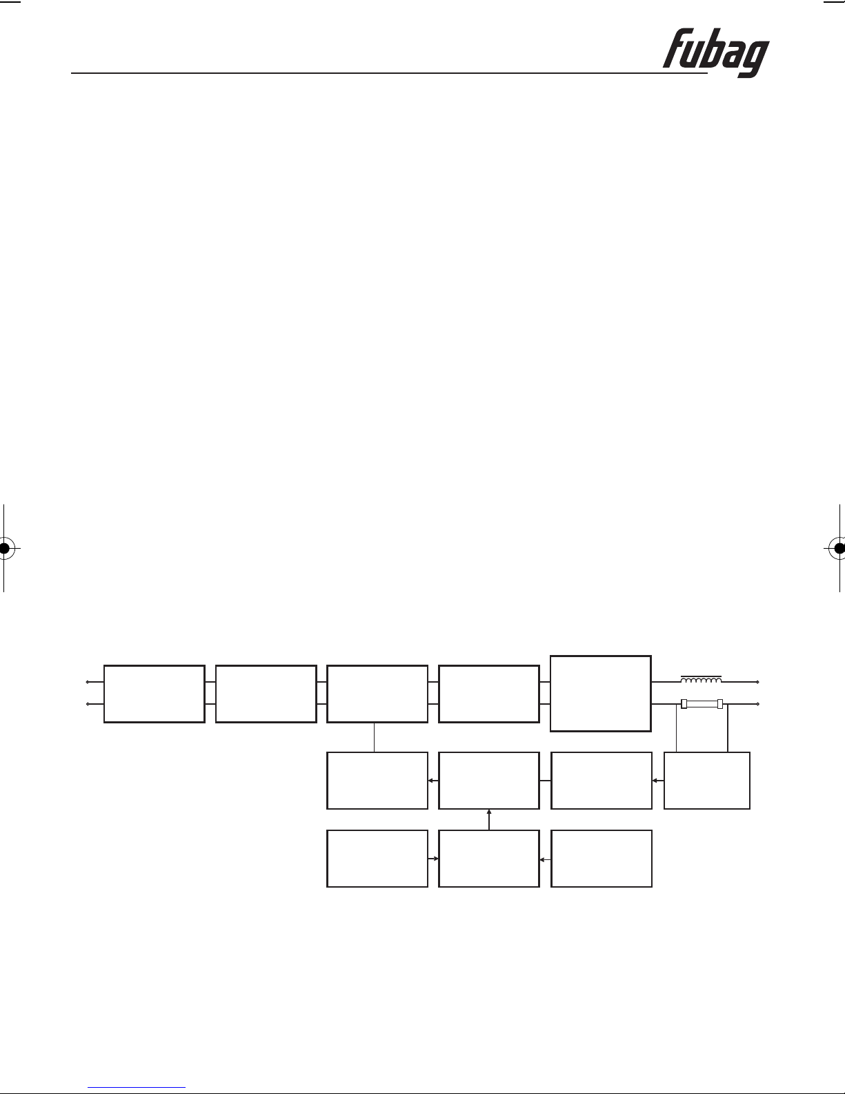
3. Description
This welding machine is designed to be used with the advanced IGBT and rapid recovery diode as
its main control and transfer components and assisted with the specially developed control circuit. It
is available to MIG (both CO gas-shielded welding and flux-cored welding) and stick welding. It
uses arc between wire and work piece as heat source to melt wire and master material metal, and
then sends shielded gas to welding site, which makes the melt pond and master material metal free
from around air s erosion. The continuous wire can form welding seam metal after melting so as to
connect the wok pieces each other. The melting electrode gas protects the welding district easily, so
it is easy to operate and observe the whole working process
The highlighted characteristics of Inverter Welder:
- Featured with small volume and light weight, it widely used in upholstering field, repairing field and
fieldwork.
- Undercutfunction make arc-piloting more successful.
’
.
2