6
WARNING
This product operates in the highly combusble atmosphere of a diesel or gasoline storage tank.
FAILURE TO COMPLY WITH THE FOLLOWING WARNINGS AND SAFETY PRECATIONS
COULD CAUSE DAMAGE TO PROPERTY, ENVIRONMENT, RESULTING IN SERIOUS INJURY
OR DEATH
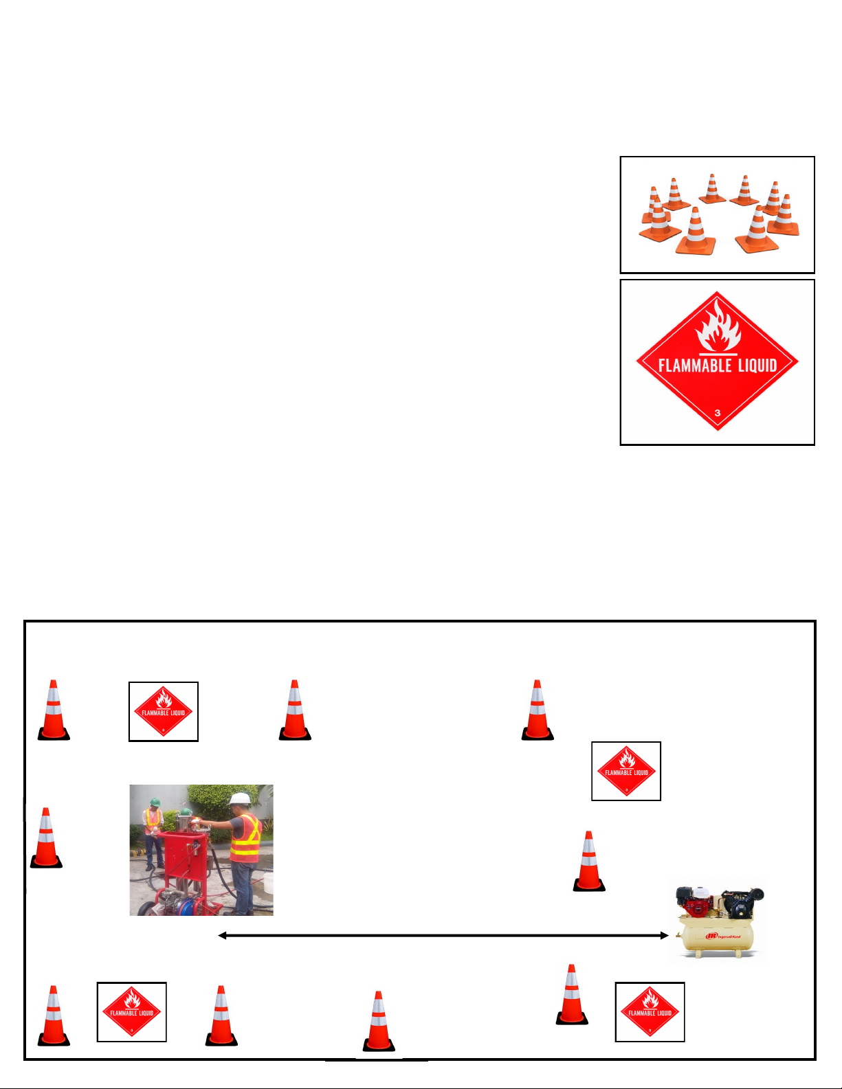
1.This fuel polishing system should NEVER BE OPERATED inside a truck cargo body, enclosed trailer, or within y (50) feet of
an operang or hot engine, motor or fuel dispenser.
2. All work must comply with the latest issue of the Naonal Electrical Code (NFPA 70), the Code for Motor Fuel
Dispensing Facilies and Repair Garages (NFPA 30A), and any European, naonal, state, and local code requirements that apply.
3. When servicing unit, use non-sparking tools and use cauon when removing or installing equipment to avoid gener-
ang a spark.
4. To protect yourself and others from serious injury, death, or substanal property damage, carefully read and follow all
warnings and instrucons in this manual.
Warnings and Instrucons
This secon introduces the hazards and safety precauons associated with operang, maintaining or servicing this product.
Before performing any task on this product, read this safety informaon and the applicable secons in this manual, where addi-
onal hazards and safety precauons for your task will be found. Fire, explosion, or pressure release could occur and cause
damage to property, environment, resulng in serious injury or death, if these safe service procedures are not followed.
Preliminary Precauons
You are working in a potenally dangerous environment of ammable fuels, vapors, and uid pressures. Only trained or au-
thorized individuals knowledgeable in the related procedures should operate, inspect, maintain or service this equipment.
Read the Manual
Read, understand and follow this manual and any other labels or related materials supplied with this equipment. If you do not
understand a procedure, call 1-828-212-1141 to locate a qualied technician. It is imperave to your safety and the safety of
others to understand the procedures before beginning work. Make sure your employees and any service contractors read and
follow the instrucons.
Follow the Regulaons
Applicable informaon is available in Naonal Fire Protecon Associaon (NFPA) 30A; Code for Motor Field Dispensing Facilies
and Repair Garages, NFPA 70; Naonal Electrical Code (NEC), Occupaonal Safety and Hazard Associaon (OSHA) regulaons
and federal, state, and local codes. All these regulaons must be followed. Failure to operate, inspect, maintain or service this
equipment in accordance with these codes, regulaons and standards may lead to legal citaons with penales or aect the
safe use and operaon of the equipment. OSHA fall protecon rules apply when working on above ground fuel storage tanks.