Preface
Thank you for purchasing our dynamic braking unit (BUC-D Series).This product is a device to discharge the braking power
to a resistor in a braking operation of the Fuji's inverter for general industry.
Read through this instruction manual to become familiar with proper handling for correct use. Improper handling might result
in incorrect operation, a short life, or even a failure of this product as well as the motor.
The related documents are subject to change without notice. Be sure to obtain the latest editions for use.
List of applicable inverters
The table below lists the inverters that can be used in combination with this product.
Inverter series Capacity Inverter type Stack/unit type
VG series All capacities FRNSVG1S-69Stack type
Table of Contents
Preface i
Safety precautions ................................................................................................................................................................. iii
Chapter 1 BEFORE USE ......................................................................................................................................................... 1
1.1 Acceptance Inspection.................................................................................................................................................. 1
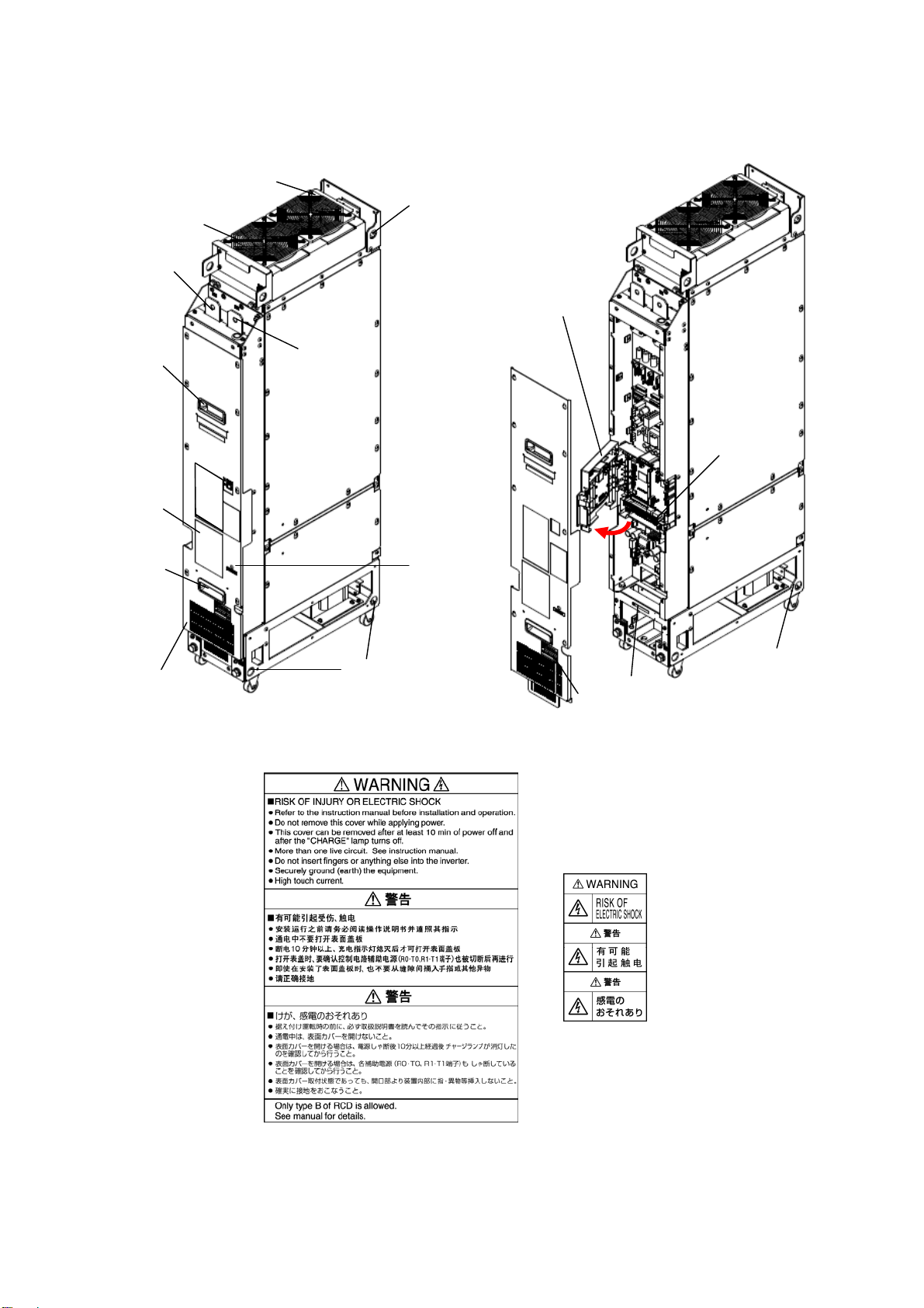
1.2 External Appearance..................................................................................................................................................... 2
1.3 Precautions for Using dynamic breaking unit............................................................................................................... 3
1.3.1 Installation environment .......................................................................................................................................3
1.3.2 Storage environment .............................................................................................................................................5
[ 1 ] Temporary storage ................................................................................................................................................5
[ 2 ] Long-term storage.................................................................................................................................................5
Chapter 2 MOUNTING AND WIRING .................................................................................................................................. 6
2.1 Mounting the dynamic breaking unit............................................................................................................................ 6
2.1.1 Terminal Arrangement and Screw Sizes (Main circuit terminals).........................................................................7
[ 1 ] Rank 4 (500 kW)................................................................................................................................................7
2.2 Wiring........................................................................................................................................................................... 8
2.2.1 Connection diagram..............................................................................................................................................8
2.2.2 Removing and mounting the front cover and the wiring guide...........................................................................10
2.2.3 Basic Connections...............................................................................................................................................11
2.2.4 Main circuit terminals.........................................................................................................................................11
[ 1 ] Screw specifications and recommended wire sizes (main circuit terminals) ....................................................11
[ 2 ] Terminal functions (main circuit terminals) .....................................................................................................12
2.2.5 Control circuit terminals .....................................................................................................................................12
[ 1 ] Screw specifications and recommended wire sizes (control circuit terminals)................................................12
[ 2 ] Terminal arrangement (control circuit terminals) .............................................................................................12
[ 3 ] Detailed functions of control circuit terminals .................................................................................................13
[ 4 ] Wiring for the control circuit............................................................................................................................16
2.2.6 Setting up the slide switches ...............................................................................................................................18
2.2.7 Fan power switching connector CN UX .............................................................................................................19
2.2.8 Connecting optical fiber cable ............................................................................................................................20
Chapter 3 TEST RUN PROCEDURE.................................................................................................................................... 21
3.1 Checking Prior to Powering On.................................................................................................................................. 21
3.2 Powering ON and Checking ....................................................................................................................................... 21
Chapter 4 TROUBLESHOOTING ........................................................................................................................................ 21
4.1 Protective Functions ................................................................................................................................................... 21
4.2 Before Proceeding with Troubleshooting ................................................................................................................... 21
4.3 Troubleshooting.......................................................................................................................................................... 22
4.3.1 List of Protective Functions................................................................................................................................22
4.3.2 Possible causes of alarms, checks and measures.................................................................................................22
[ 1 ] Overcurrent ......................................................................................................................................................22
[ 2 ] Overvoltage ......................................................................................................................................................23
[ 3 ] DC Fuse blown.................................................................................................................................................23
[ 4 ] Memory error ...................................................................................................................................................23
i