Fuji Electric Profibus OPC-F1-PDP User manual

Instruction Manual
Profibus®Interface Card "OPC-F1-PDP"
Thank you for purchasing our PROFIBUS DP Interface Card OPC-F1-PDP.
• This product is designed to connect the FRENIC-Eco series of inverters to PROFIBUS DP
Communications Network. Read through this instruction manual and be familiar with the
handling procedure for correct use.
• Improper handling blocks correct operation or causes a short life or failure.
• Deliver this manual to the end user of the product. The end user should keep this manual in a
safe place until the PROFIBUS DP Interface Card is discarded.
• For the usage of inverters, refer to the instruction manual prepared for the FRENIC-Eco series
of inverters.
Fuji Electric Systems Co., Ltd. INR-SI47-1144-EU REV 052010

Copyright © 2006 Fuji Electric FA Components & Systems Co., Ltd.
All rights reserved.
No part of this publication may be reproduced or copied without prior written permission from Fuji Electric FA Components & Systems Co.,
Ltd.
All products and company names mentioned in this manual are trademarks or registered trademarks of their respective holders.
The information contained herein is subject to change without prior notice for improvement.

Preface
Thank you for purchasing our PROFIBUS DP Interface Card OPC-F1-PDP.
Installing this card on your FRENIC-Eco allows you to connect the FRENIC-Eco to a PROFIBUS DP master node (e.g., PC and PLC) and
control it as a slave unit using run and frequency commands, and access to function codes.
This product is certificated by a test laboratory officially approved by the PROFIBUS Organization and fully compliant with the PROFIBUS
DP-V0 protocol.
How this manual is organized
This manual is made up of chapters 1 through 13.
Chapter 1 FEATURES
Gives an overview of the main features of the PROFIBUS DP interface card.
Chapter 2 ACCEPTANCE INSPECTION
Lists points to be checked upon delivery of the card and precautions for transportation and storage of the card. Also this chapter presents the
appearance of the card and provides information on how to obtain a GSD file.
Chapter 3 FUNCTIONS AND CONFIGURATION OF THE CARD
Provides instructions on how to use the node address switches, terminating resistor switch and status indicator LEDs.
Chapter 4 INSTALLATION
Provides instructions and precautions for installing the card.
Chapter 5 WIRING
Provides wiring instructions around the terminal blocks on the card and the cable specifications.
Chapter 6 FUNCTION CODE SETTINGS REQUIRED FOR PROFIBUS COMMUNICATION
Describes the inverter's function codes to be set for receiving run and frequency commands via a PROFIBUS DP master node. It also lists the
related function codes.
Chapter 7 ESTABLISHING A PROFIBUS COMMUNICATIONS LINK
Guides you to establish a PROFIBUS DP communications link between the PROFIBUS DP master node and this card (slave node).
Chapter 8 QUICK SETUP GUIDE FOR RUNNING THE INVERTER
Describes a simple profile (data format) dedicated to inverter’s run and frequency commands, taking the actual data transaction data as an
example.
Chapter 9 DETAILS OF PROFIBUS DP PROFILES
Details PROFIBUS DP profile data formats and parameters supported by this card. Furthermore, this chapter describes how the master node
accesses inverter’s function codes.
Chapter 10INVERTER REACTION TO PROFIBUS COMMUNICATIONS ERRORS
Describes on how the inverter operates if a PROFIBUS communications error occurs.
Chapter 11 ALARM CODE LIST
Lists and explains inverter’s alarm codes.
Chapter 12TROUBLESHOOTING
Provides troubleshooting instructions for certain problems, e.g., when the inverter does not operate as ordered or when an alarm condition
has been recognized.
Chapter 13SPECIFICATIONS
Lists the general specifications and communications specifications.
1

Icons
The following icons are used throughout this manual.
This icon indicates information which, if not heeded, can result in the product not operating to full efficiency, as well as information
concerning incorrect operations and settings which can result in accidents.
This icon indicates information that can prove handy when performing certain settings or operations.
This icon indicates a reference to more detailed information.
Table of Contents
Preface .....................................................1 Chapter 8QUICK SETUP GUIDE FOR
How this manual is organized.......................1 RUNNING THE INVERTER........................11
8.1 11Before Proceeding to Data Exchange
Chapter 1 ..................................3FEATURES 8.2 ..........................................11
Data Transaction Examples in Running
an Inverter
Chapter 2 ACCEPTANCE INSPECTION .....3
Chapter 9 DETAILS OF PROFIBUS
Chapter 3 FUNCTIONS AND PROFILES..................................................14
CONFIGURATION OF THE CARD...............4 9.1 .14Description of PPO Types Supported
3.1 ...........................4Status Indicator LEDs 9.2 ..................................16PCD Word Area
3.2 ........................5Node Address Switches 9.3 ..................................21PCV Word Area
3.3 .................5Terminating Resistor Switch
3.4 .....................................5Terminal Board Chapter 10 INVERTER REACTION TO
3.5 Setting the Transmission Speed PROFIBUS COMMUNICATIONS
(Baud rate)..................................................5 ERRORS ................................................28
Chapter 4 ...........................6INSTALLATION Chapter 11ALARM CODE LIST..................29
Chapter 5 .......................................7WIRING Chapter 12 ...........30TROUBLESHOOTING
Chapter 6 FUNCTION CODE SETTINGS Chapter 13 ..................31SPECIFICATIONS
REQUIRED FOR PROFIBUS 13.1 ...................31General Specifications
COMMUNICATION .......................................9 13.2 .....31Communications Specifications
Chapter 7 ESTABLISHING A PROFIBUS
COMMUNICATIONS LINK..........................10
2

Chapter 1 FEATURES
The PROFIBUS DP interface card has the following features:
- PROFIBUS version: DP-V0
- Transmission speed: 9.6 Kbps to 12 Mbps
- Maximum network cable length per segment: 100 m (12 Mbps) to 1200 m (9.6 Kbps)
- Profile: PROFIdrive V2
- Able to read and write all function codes supported in FRENIC-Eco
Chapter 2 ACCEPTANCE INSPECTION
Unpack the package and check that:
(1) A PROFIBUS DP interface card is contained in the package.
(2) The card has not been damaged during transportation--no defective electronic devices, dents, or warp.
(3) The model name "OPC-F1-PDP" is printed on the card. (See Figure 1.)
If you suspect the product is not working properly or if you have any questions about your product, contact your Fuji Electric representative.
This card is applicable to all FRENIC-Eco series of inverters and all software versions.
IMPORTANT
AGSD file, which is required for registering the PROFIBUS DP interface card to the PROFIBUS master node, does not come with the card. It
is available as a free download from our website at:
http://web1.fujielectric.co.jp/Kiki-Info-EN/User/index.html
(Fuji Electric FA Components & Systems Co., Ltd. Technical Information site)
Before downloading, you are requested to register as a member (free of charge).
Figure 1 Front of the Card Figure 2 Back of the Card
Ground terminal block
PROFIBUS
terminal block Node address
switches
Terminating resisto
r
switch 4 spacers CN1
Model
name
Status indicator LEDs
3

Chapter 3 FUNCTIONS AND CONFIGURATION OF THE CARD
3.1 Status Indicator LEDs
This interface card has four status indicator LEDs shown in Figure 3. They indicate the operation status of the card as listed in Table 1.
Figure 3 Status Indicator LEDs
Table 1 LED Indications and Operation Status
Name Color Meaning Note
Lights in green Normal ---
Blinks in green Self-diagnostic test running or initialization
in progress during powering on sequence This test takes approx.
0.5 second.
Blinks in red PROFIBUS communications error The inverter shows er5.
*1
PWR
Lights in red Hardware error
(Card not properly installed or card faulty) The inverter shows er4.
Wrong configuration of PROFIBUS
protocol
(Discrepancy between PPO type defined
by the inverter's function code o30 and the
one defined in the PROFIBUS master
node)*2
---
ERR
Blinks in red
Wrong configuration of PROFIBUS
protocol
(The node address is set to 126 or
greater.)
The inverter shows er5.
*1
Lights in green Online
(The card communicates normally on the
PROFIBUS network.) ---
ONL
OFF Not online ---
Lights in red Offline
(The card is not connected to PROFIBUS) ---
OFFL OFF Not offline ---
*1Configuration for ignoring er5 is possible. For details, refer to Chapter 10, "INVERTER REACTION TO PROFIBUS COMMUNICATIONS
ERRORS."
*2PPO (Parameter Process-data Object) type defined in this card should be consistent with that in the PROFIBUS DP master node. To define the
PPO type in this card, use the inverter's function code o30; to define that in the master node, use a configuration tool designed for the master
node.
For defining the PPO type in the master node, refer to the documentation of the master node.
For details about the PPO type, see Chapter 9, "DETAILS OF PROFIBUS PROFILES." For details about the function code o30, see Chapter
6 "FUNCTION CODE SETTINGS REQUIRED FOR PROFIBUS COMMUNICATION."
4

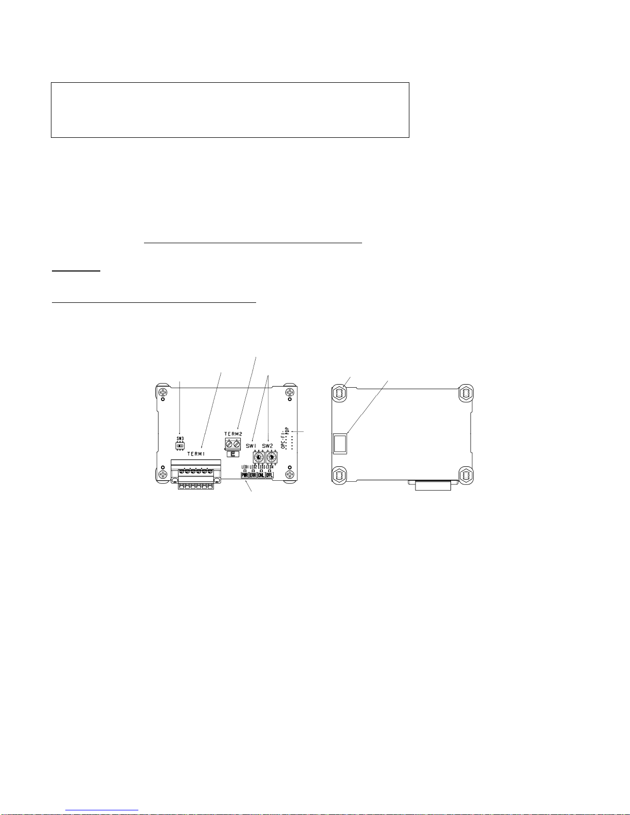
3.2 Node Address Switches
The node address switches (SW1 and SW2) on the interface card are rotary ones that are used to specify the PROFIBUS DP communications
network node address (station address) of the card. The setting range is from 0 to 99 in decimal. The SW1 specifies a 10s digit of the node address
and the SW2, a 1s digit.
The node address can also be specified with the inverter's function code o31. The setting range is from 0 to 125 in decimal. Note that validating the
node address specified with the function code o31 requires setting the node address switches to "00."
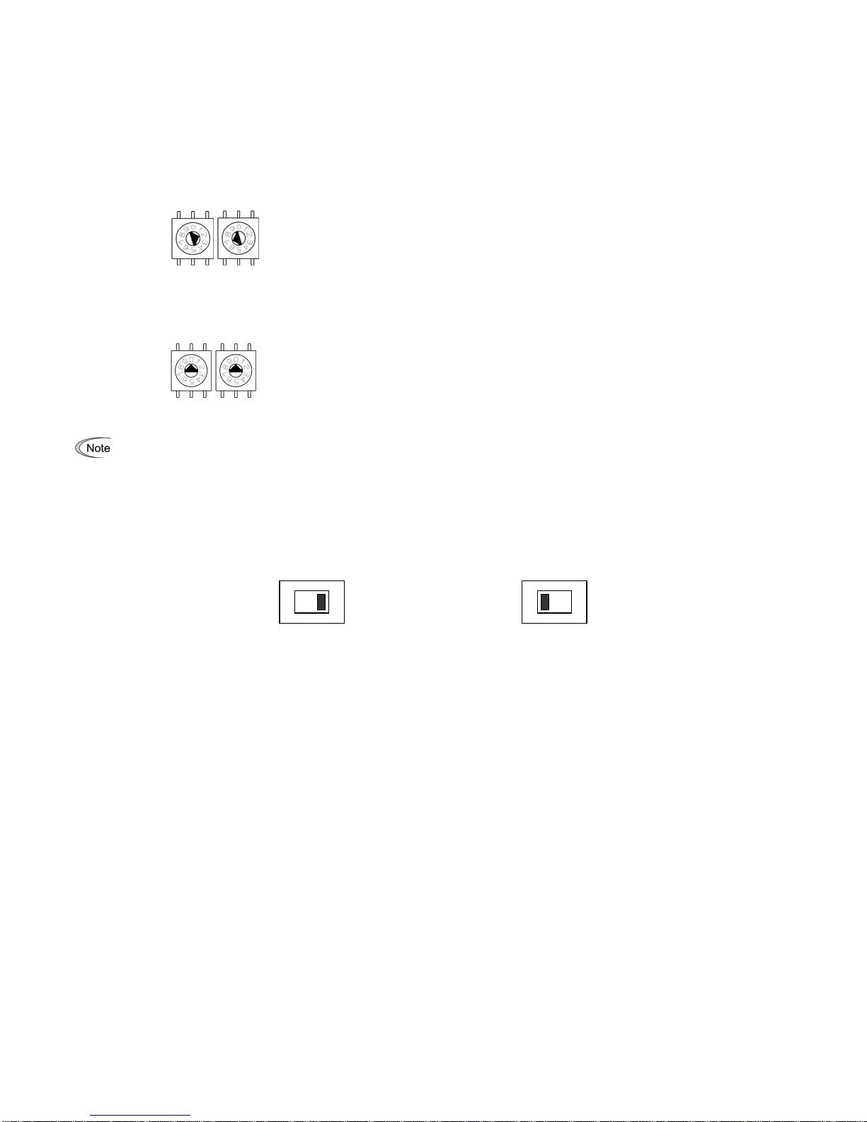
Example 1: Setting the node address 27 using the node address switches
SW1 SW2
1. When the inverter is powered OFF:
Set SW1 to "2."
Set SW2 to "7."
2. Turn the inverter power ON.
The setting procedure is completed.
Figure 4 Node Address Setting Example 1
Example 2: Setting the node address 125 using the function code o31
SW1 SW2
Figure 5 Node Address Setting Example 2
1. When the inverter is powered OFF:
Set both the SW1 and SW2 to "0."
2. Turn the inverter power ON and set the function code o31 data to "125."
3. Turn the inverter power OFF and ON.
The setting procedure is completed.
1. The node address switches should be accessed with all the inverter power (including the auxiliary power) being OFF. Setting
these switches with the inverter power being ON requires turning the power OFF and ON to validate the new setting.
2. To validate the node address setting using the function code o31, restart the inverter.
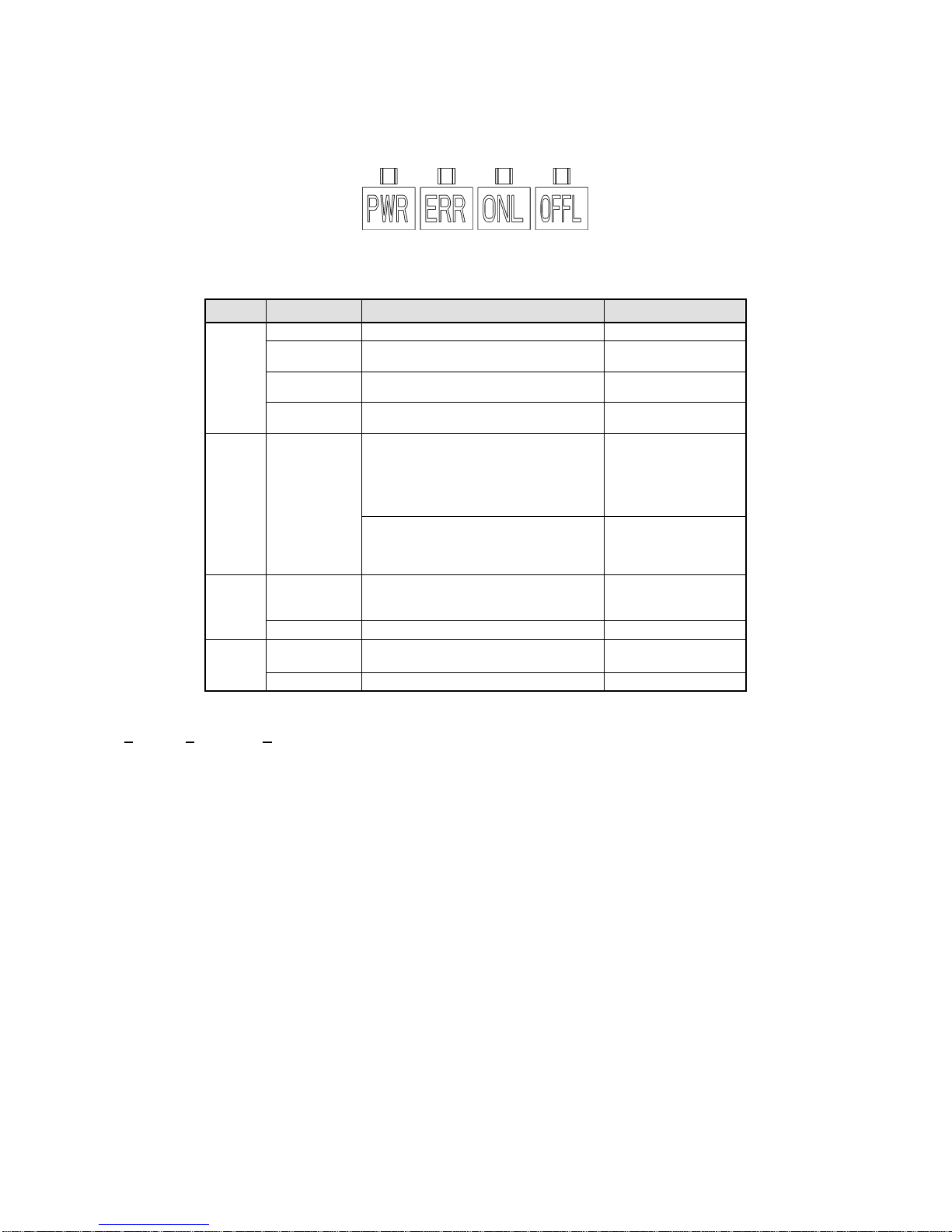
3. Setting the function code o31 data to "126" or greater will cause a data setting error. The ERR LED on the card blinks in red and
the inverter issues the alarm code er5.
3.3 Terminating Resistor Switch
The PROFIBUS DP communications network requires insertion of line terminating resistors at its end. When the card is mounted in the inverter at
the end of the network, turn this switch ON to insert the terminating resistor. No external terminating resistor is required.
OFF: No insertion of terminating resistor ON: Insertion of terminating resistor
Figure 6 Terminating Resistor Switch
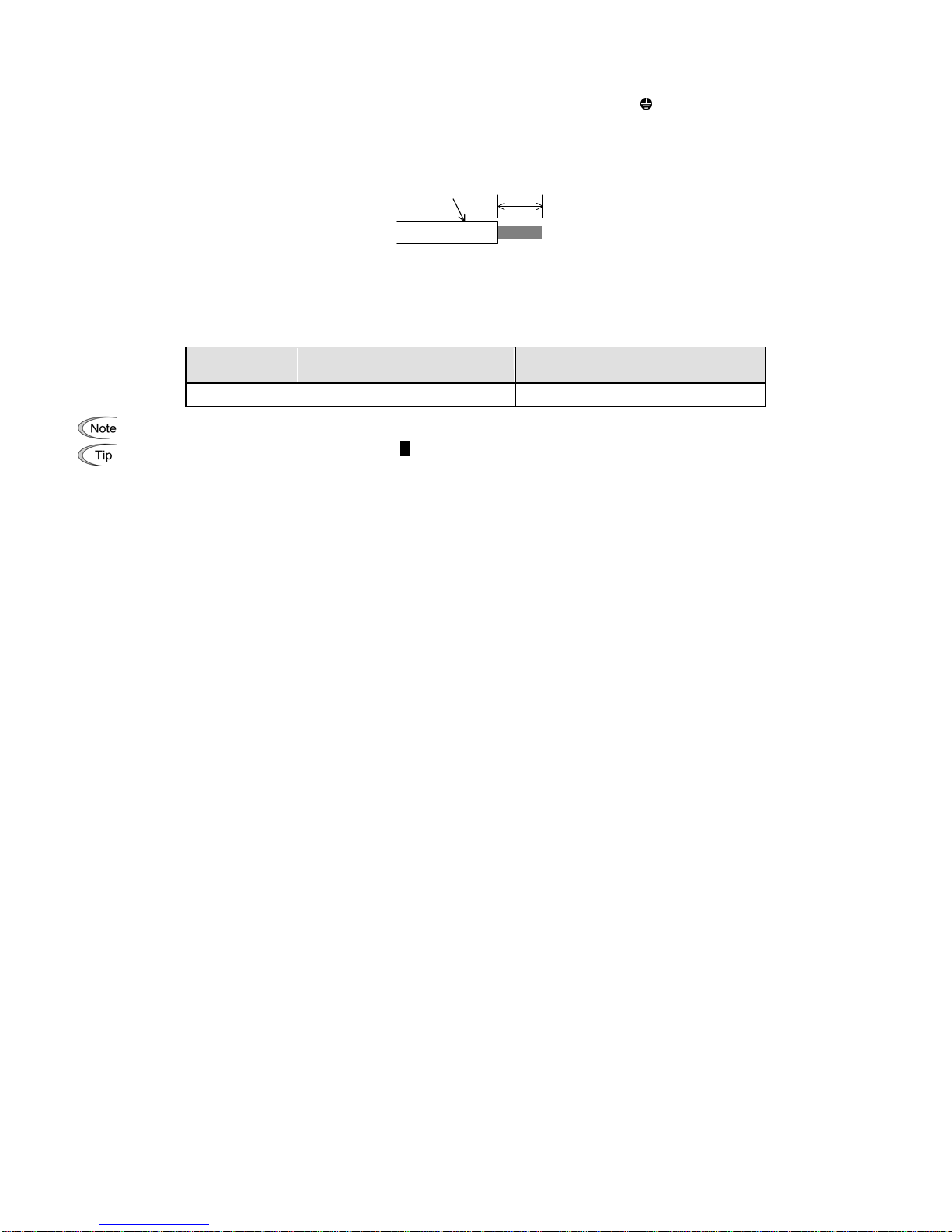
3.4 Terminal Board
This card provides two terminal blocks, one for the PROFIBUS communications and another for grounding (earthing).
For wiring of the terminal blocks, refer to Chapter 5 "WIRING."
3.5 Setting the Transmission Speed (Baud rate)
No transmission speed setting is required on the interface card (slave). Setting the transmission speed in the PROFIBUS DP network master node
automatically configures the transmission speed of this card.
5

Chapter 4 INSTALLATION
Turn the power OFF and wait for at least five minutes for inverters of 40 HP or below, or ten minutes for inverters of 50 HP or above, before
starting installation. Further, check that the LED monitor and charge lamp are unlit, and check the DC link circuit voltage between the P (+) and N
(-) terminals to be lower than 25 VDC.
Otherwise, electric shock could occur.
Do not touch any metallic part of the connector for the main unit (CN1) or any electronic component. Otherwise, electronic components may be
damaged by static electricity charged in your body. Also, the stain or adhesion of sweat or dust may adversely affect the contact reliability of the
connector in the long run.
An accident could occur.
(1) Remove the covers from the inverter to expose the control printed circuit (Figure 7).
For the removal instructions, refer to the FRENIC-Eco Instruction Manual (INR-SI47-1225-E), Chapter 2, Section 2.3 "Wiring." (For
inverters of 50 HP or above, also open the keypad enclosure.)
(2) Insert four spacers and connector CN1 on the back of the OPC-F1-PDP (Figure 2) into the four spacer holes and Port A(CN4) on the inverter's
control printed circuit board (PCB) (Figure 8), respectively.
Make sure, visually, that the spacers and CN1 are firmly inserted (Figure 9).
(3) Install the wires for the OPC-F1-PDP.
For wiring instructions, see Chapter 5 "WIRING.".
(4) Put the covers back to their original positions.
For the installation instructions, refer to the FRENIC-Eco Instruction Manual (INR-SI47-1225-E), Chapter 2, Section 2.3 "Wiring." (For
inverters of 50 HP or above, also close the keypad enclosure.)
Figure 7 FRN010F1S-2U to
FRN020F1S-2U
(example)
Figure 8 Mounting the Card Figure 9 Mounting Completed
Control PCB
4 spacer holes
4 spacers
Make sure that
there is no gap
between control
PCB and spacers.
Port A
(CN4)
PROFIBUS DP interface card,
OPC-F1-PDP CN1
6

Chapter 5 WIRING
(1) Use a shielded twist pair cable that complies with the PROFIBUS specifications.
The recommended cable is 6XV1 830-0EH10 manufactured by Siemens AG.
For details about wiring for PROFIBUS, refer to the "Installation Guideline for PROFIBUS DP/FMS" and "Handbook PROFIBUS
Installation Guideline" published by the PROFIBUS Organization. It can be downloaded for free from the PROFIBUS Organization's
website at:
http://www.profibus.com/pall/meta/downloads/
(2) Wiring to the PROFIBUS terminal block (TERM1)
The terminal block uses a 6-pin connector shown in Figure 10. Table 2 shows the pin assignment.
The applicable connector is "MC1.5/6-STF-3.81" manufactured by Phoenix Contact Inc.
Before connecting the PROFIBUS cable to the terminal block, strip the cable wire end and twist the core and shield wires. Figure 11 shows the
recommended wire strip length. Table 3 lists the recommended tightening torque of the terminal screws and the wire size.
Table 2 Pin Assignment on TERM1
Pin
# Pin
Assignme
nt Description
1 +5V BUS Not used.
2 GND BUS Not used.
3 A-Line Terminal for the negative (-) line
of PROFIBUS cable (green wire)
4 B-Line Terminal for the positive (+) line
of PROFIBUS cable (red wire)
5 Shield
*Terminal for connecting the
cable shield
6 RTS Data transmission control for the
repeater
(direction control)
123456
Figure 10 Connectors of the
PROFIBUS Terminal Block
*The Shield terminal on the TERM1 and Ground terminal(s) on the TERM2 are connected internally.
Figure 11 Recommended Strip Length of the PROFIBUS Cable Wire End for Terminal Connection
Table 3 Recommended Tightening Torque of the Terminal Screws and
Wire Size for the PROFIBUS Terminal Block
A
pprox.
5.5 mm(0.22 In)
Cable wire
Terminal Screw
Size Tightening Torque Wire Size
M2 0.22 to 0.25 N·m(0.16 to 0.18 lbf·ft) AWG28 toAWG16 (0.14 to 1.5 mm2)
Keep the PROFIBUS cable away from the main power supply wires of the inverter and the motor power cable and other devices as
far as possible.
7

(3) Wiring to the ground terminal block (TERM2)
Using a wire, connect either one of the two ground terminals* on the TERM2 to the grounding terminal ( G) on the inverter. (*These two terminals
on the TERM2 are internally connected.)
Figure 12 shows the recommended wire end strip length for the card connector. Table 4 shows the recommended tightening torque of the terminal
screws and its tightening torque, and the wire size.
A
pprox.
6.0 mm(0.24 in)
Grounding wire
Figure 12 Recommended Strip Length of the Grounding Wire
Table 4 Recommended Tightening Torque of the Terminal Screws and
Wire Size for the Ground Terminal Block (TERM2)
Terminal screw
size Tightening torque Wire size
M3 0.5 to 0.6 N·m(0.37 to 0.44 lbf·ft) AWG17 to AWG16 (1.0 to 1.5 mm2)
To keep noise immunity high, be sure to connect a grounding wire to the terminal block.
The ground terminal block TERM2 is marked with Eby its side. "E" signifies earth (ground).
The ground terminal(s) on the TERM2 and the Shield terminal on the TERM1 are connected internally, so this connection grounds
the shield of the PROFIBUS cable if the inverter is grounded.
(4) Switching the terminating resistor ON/OFF
When the cards are mounted on the inverters at both ends of network, turn the SW3 ON to insert the terminating resistors.
For details, refer to Chapter 3, Section 3.3 "Terminating Resistor Switch."
8

Chapter 6 FUNCTION CODE SETTINGS REQUIRED FOR PROFIBUS COMMUNICATION
To perform data transmission between the inverter equipped with this card and the PROFIBUS DP master node, configure the function codes listed
in Table 5.
Tables 5 and 6 list inverter's function codes related to PROFIBUS DP communication. Configure those function codes if necessary.
For details about function codes, refer to the FRENIC-Eco Instruction Manual (INR-SI47-1225-E), Chapter 5 "FUNCTION CODES" and
RS-485 Communication User's Manual (MEH448), Chapter 5, Section 5.2 "Data Formats."
Table 5 Inverter's Function Code Settings Related to PROFIBUS Communications
Function
codes Description Factory
default
setting Function code data Remarks
o30 *1 Select PPO type (data
format) 0 Available data is:
0, 1, 6 to 255: PPO type 1
2 and 5: PPO type 2
3: PPO type 3
4: PPO type 4
The selected PPO type
should be consistent
with that of the master
node.
y98 *2 Select run/frequency
command source 0 Available data is:
Frequency
command Run
command
0 Inverter Inverter
1 PROFIBUS Inverter
2 Inverter PROFIBUS
3 PROFIBUS PROFIBUS
If there is no special
problem with your
system, setting y98 = 3
is recommended.
*1After setting up the function code o30, turn the inverter power OFF and ON to validate the new setting.
For details about the function code o30, refer to Chapter 9 "DETAILS OF PROFIBUS PROFILES."
*2In addition to y98, the FRENIC-Eco has other function codes related to the run/frequency command source. Setting up those codes realizes
more precise selection of the command sources. For details, refer to the descriptions of H30 and y98 in the FRENIC-Eco Instruction Manual
(INR-SI47-1225-E), Chapter 5 "FUNCTION CODES."
Table 6 Other Related Function Codes
Function
codes Description Factory
default
setting
Function code setting
range Remarks
o27 *1 Select the inverter’s operation mode to apply
when a PROFIBUS communications error
occurs.
0 0 to 15
o28 *1 Set the operation timer to apply when a
PROFIBUS communications error occurs. 0.0 s 0.0 s to 60.0 s
o31 *2Set the PROFIBUS network node address. 0 0 to 255
(Setting range: 0 to 125) Valid only when both SW1
and SW2 are set to "00."
Setting 126 or greater
causes an error, flashing the
ERR LED and issuing an er5.
o40 to o43
*3 Assign the function code writing data
cyclically. 0
(No
assignment)
0000 to FFFF (hex)
o48 to o51
*3 Assign the function code reading data
cyclically. 0
(No
assignment)
0000 to FFFF (hex)
Valid only when PPO type 2
or 4 is selected.
W90 Show the software version of the PROFIBUS
interface card on the LED monitor. Depends on
the card ---
(Only for monitoring) 4-digit decimal
If the version is V.1.23, the
LED shows "0123."
*1For details about function codes o27 and o28, refer to Chapter 10 "INVERTER REACTION TO PROFIBUS COMMUNICATIONS ERRORS."
*2For details about the function code o31, refer to Chapter 3, Section 3.2 "Node Address Switches."
*3For details about function codes o40 to o43 and o48 to o51, refer to Chapter 9, Section 9.2 (4) "PCD1 to PCD4."
9

Chapter 7 ESTABLISHING A PROFIBUS COMMUNICATIONS LINK
This chapter guides you to establish a PROFIBUS DP communications link between the PROFIBUS DP master node and this card (slave node).
Follow the steps below.
Step 1 Configuring the PROFIBUS DP master node equipment
Step 2 Configuring this card and inverter's function codes
Step 3 Powering ON the inverter and initiating the PROFIBUS data transaction
Each of the above steps is detailed below.
Step 1 Configuring the PROFIBUS DP master node equipment
Step 1.1:Specify the master node address (station address) and baud rate.
Step 1.2:Register this card to the master node using the GSD file prepared for the card.
Step 1.3:Choose a PPO type (data format) to be applied to the registered card, from PPO type 1 to PPO type 4.
For details about the configuration of the PROFIBUS DP master node equipment, refer to the user’s manual or documentations of your master
equipment.
For details about PPO types, refer to Chapter 9 "DETAILS OF PROFIBUS DP PROFILES."
IMPORTANT
A GSD file, which is required for registering the PROFIBUS DP interface card to the PROFIBUS
master node, does not come with the card. It is available as a free download from our website at:
http://web1.fujielectric.co.jp/Kiki-Info-EN/User/index.html
(Fuji Electric FA Components & Systems Co., Ltd. Technical Information site)
Before downloading, you are requested to register as a member (free of charge).
Step 2 Configuring this card and inverter’s function codes
Step 2.1:Specify the node address that must be identical with the card address registered to the master node.
Step 2.2:Set up the data of inverter function codes o27 and o28, if needed.
Step 2.3:Choose a PPO type from PPO type 1 to PPO type 4, using the inverter’s function code o30.
The PPO type must be identical with the one selected for the master node. After changing the data of the function code o30, be sure to
turn the inverter power OFF and ON.
For details about function codes o27 and o28, refer to Chapter 10 "INVERTER REACTION TO PROFIBUS COMMUNICATIONS ERRORS."
Step 3 Powering ON the inverter and initiating the PROFIBUS data transaction
When the inverter equipped with this card and the PROFIBUS DP master node are correctly set up, turning the inverter OFF and ON automatically
establishes a PROFIBUS communications link, enabling the data transaction between them. The PWR and ONL LEDs on the card light in green.
Send run and frequency commands from the master to this card.
For specific data formats and data transaction, refer to Chapter 8 "QUICK SETUP GUIDE FOR RUNNING THE INVERTER" and Chapter 9
"DETAILS OF PROFIBUS DP PROFILES."
For the wiring, refer to Chapter 5 "WIRING."
10

Chapter 8 QUICK SETUP GUIDE FOR RUNNING THE INVERTER
This chapter provides a quick setup guide for running the inverter from a PROFIBUS DP master node according to the simplest data format (PPO
type 3), taking an operation example. PPO type 3 is a simple format dedicated to inverter’s run and frequency commands.
The description of PPO type 3 in this chapter can apply to other PPO types, except the
format assignment maps.
To simplify the description, this chapter confines the description to running of an inverter. For more information, refer to Chapter 9 "DETAILS
OF PROFIBUS DP PROFILES."
8.1 Before Proceeding to Data Exchange
(1) At the PROFIBUS DP master node, select PPO type 3 for this interface card.
For the setting procedure of PPO types at the PROFIBUS DP master node, refer to the user's manual of your master node equipment.
(2) Set function codes of your inverter as follows.
F03 = 60 (Maximum frequency in Hz), y98 = 3 (Validate frequency and run commands from PROFIBUS), and o30 = 3 (Select PPO type 3)
Also set the data of function codes o27 and o28, if needed.
After settings are completed, turn the inverter power OFF and ON to validate the new settings.
For details about function codes o27 and o28, refer to Chapter 10 "INVERTER REACTION TO PROFIBUS COMMUNICATIONS
ERRORS."
8.2 Data Transaction Examples in Running an Inverter
Before providing data transaction examples, this section shows the data frame formats of PPO type 3. The following descriptions are based on
these formats.
(
B
y
te
)
0 1 2 3
Request
(Master Slave) CTW MRV
CTW:Control word (2 bytes) that sends a run command. The LSB determines ON/OFF of the run command.
MRV: Sends a frequency command that is expressed relative to the maximum frequency (defined by F03 in Hz) being assumed as
4000hex.
(
B
y
te
)
0 1 2 3
Response
(Salve Master) STW MAV
STW:Status word (2 bytes) that sends the running status of the inverter to be monitored at the master node.
MAV: Sends the current output frequency of the inverter to be monitored at the master node, which is expressed relative to the maximum
frequency (defined by F03 in Hz) being assumed as 4000hex.
Given below is a PROFIBUS DP communication sample in which the master node runs the inverter in the forward direction in 60 Hz.
(1) Turning the inverter power ON initiates PROFIBUS DP communication. Immediately after the power is ON, the data in the request/response
frames is as follows.
(
B
y
te
)
0 1 2 3
00 00 00 00
Request
(Master Slave) CTW MRV
(
B
y
te
)
0 1 2 3
02 40 00 00
Response
(Salve Master) STW MAV
STW:Data 02 indicates that frequency and run commands from PROFIBUS are enabled. Data 40 indicates that the inverter is not ready
to turn a run command ON.
MAV: Data 0000 means that the current output frequency is 0 Hz.
11

(2) In step (1), the inverter is not ready to turn a run command ON as shown in STW.
First, enter the request data "04 7E" to CTW, to make the inverter ready to turn a run command ON. In the example below, the frequency
command 60 Hz (maximum frequency being assumed as 4000hex) is entered to MRV at the same time.
(
B
y
te
)
0 1 2 3
04 7E 40 00
Request
(Master Slave) CTW MRV
CTW:Data 04 enables the contents in this frame. Data 7E requests the inverter to get ready to turn a run command ON.
MRV: The frequency command is 4000hex (= Maximum frequency defined by F03 in Hz).
In response to the above request, this interface card returns the following response to the master node.
(
B
y
te
)
0 1 2 3
02 31 00 00
Response
(Salve Master) STW MAV
STW:Data 02 indicates that frequency and run commands from PROFIBUS are enabled. Data 31 indicates that the inverter is ready to
turn a run command ON.
MAV: The current output frequency is 0 Hz.
(3) Since the inverter has been ready to turn a run command ON, enter run command data "04 7F" to CTW.
(
B
y
te
)
0 1 2 3
04 7F 40 00
Request
(Master Slave) CTW MRV
CTW:Data 04 enables the contents in this frame. Data 7F requests the inverter to turn a run command ON.
MRV: The frequency command is 4000hex (= Maximum frequency defined by F03 in Hz).
In response to the above request, the inverter starts running the motor. The card returns the following response to the master node.
(
B
y
te
)
0 1 2 3
02 37 ** **
Response
(Salve Master) STW MAV
STW:Data 02 indicates that frequency and run commands from PROFIBUS are enabled. Data 37 indicates that the inverter is running.
MAV: The output frequency is accelerating.
(4) To stop the inverter, enter data "04 7E" to CTW.
(
B
y
te
)
0 1 2 3
04 7E 40 00
Request
(Master Slave) CTW MRV
CTW:Data 04 enables the contents in this frame. Data 7E requests the inverter to turn the run command OFF.
MRV: The frequency command is 4000hex (= Maximum frequency defined by F03 in Hz).
In response to the above request, the inverter decelerates to a stop. The card returns the following response to the master node.
(
B
y
te
)
0 1 2 3
02 33/31 ** **
Response
(Salve Master) STW MAV
STW:Data 02 indicates that frequency and run commands from PROFIBUS are enabled. Data 33 indicates that the inverter is
decelerating, and data 31 indicates that the inverter is ready to turn a run command ON (when the inverter is stopped).
MAV: The output frequency is decreasing.
12

(5) To restart running the inverter, enter data "04 7F" to CTW. To run the inverter in the reverse direction, enter data "0C 7F" instead.
The example below specifies "Run reverse at the frequency of 30 Hz (2000hex)."
(
B
y
te
)
0 1 2 3
0C 7F 20 00
Request
(Master Slave) CTW MRV
CTW:Data 0C enables the contents in this frame and requests the inverter to turn a run reverse command ON. Data 7F requests the
inverter to turn a run command ON.
MRV: The frequency command is 2000hex (Frequency (Hz) = F03 2000hex/4000hex).
In response to the above request, the inverter starts running the motor in the reverse direction. The example below shows a response
indicating that the inverter has reached the commanded frequency level in the reverse direction.
(
B
y
te
)
0 1 2 3
02 37 E0 00
Response
(Salve Master) STW MAV
STW:Data 02 indicates that frequency and run commands from PROFIBUS are enabled. Data 37 indicates that the inverter is running.
MAV: The current output frequency is E000hex (2’s complement expression of 2000hex (Frequency = F03 -2000hex/4000hex).
(6) Entering a negative value to MRV also allows the inverter to run in the reverse direction. The example below enters E000hex, 2’s complement
of 2000hex.
(
B
y
te
)
0 1 2 3
04 7F E0 00
Request
(Master Slave) CTW MRV
CTW:Data 04 enables the contents in this frame. Data 7F requests the inverter to turn a run command ON.
MRV: The frequency command is E000hex (-2000hex) (Frequency = F03 -2000hex/4000hex).
In response to the above request, the inverter starts running the motor in the reverse direction. The example below shows a response
indicating that the inverter has reached the commanded frequency level in the reverse direction.
(
B
y
te
)
0 1 2 3
02 37 E0 00
Response
(Salve Master) STW MAV
STW:Data 02 indicates that frequency and run commands from PROFIBUS are enabled. Data 37 indicates that the inverter is running.
MAV: The current output frequency is E000hex (Frequency = F03 -2000hex/4000hex).
(7) If any trip occurs in the inverter, remove the trip factor and then enter data "04 80" to CTW to cancel the trip. After the trip is cancelled, enter data
"04 00." (Note: The MSB in the 2nd byte (Byte 1) acts as a trip cancellation bit.)
(
B
y
te
)
0 1 2 3
04 80 10 00
Request
(Master Slave) CTW MRV
CTW:Data 04 enables the contents in this frame. Data 80 requests canceling of the trip.
MRV: The frequency command is 1000hex (Frequency = F03 1000hex/4000hex).
Canceling a trip returns the inverter to the state immediately after the power is turned ON. To restart operation using PROFIBUS network,
go back to step (2).
(
B
y
te
)
0 1 2 3
02 40 00 00
Response
(Salve Master) STW MAV
STW:Data 02 indicates that frequency and run commands from PROFIBUS are enabled. Data 37 indicates that the inverter is running.
MAV: The current output frequency is 0000hex.
13

Chapter 9 DETAILS OF PROFIBUS PROFILES
The interface card supports PROFIdrive V2 of a motor control profile which is instituted by the PROFIBUS Organization. This chapter describes the
PROFIdrive profile.
9.1 Description of PPO Types Supported
The PROFIdrive profile defines several data formats called PPO (Parameter Process-data Object). This interface card supports four PPO types
shown in Figure 13. Select a PPO type to apply to the card using the function code o30 (see Table 7). Table 8 lists the features of these PPO types.
Tables 9 and 10 list the parts in the PPO.
PCV PCD
(Word
/Area) PCA IND PVA CTW
STW MRV
MAV PCD1 PCD2 PCD3 PCD4
(Word) 1 2 3 4 5 6
PPO
type 1
(Word) 1 2 3 4 5 6 7 8 9 10
PPO
type 2
(Word) 1 2
PPO
type 3
(Word) 1 2 3 4 5 6
PPO
type 4
Figure 13 Data Formats of PPO Types Supported
Table 7 Choice of PPO Type Using the Inverter's Function Code o30
Data of o30 PPO Remarks
0, 1, 6 to 255 PPO type 1 Factory default PPO type
2, 5 PPO type 2
3 PPO type 3
4 PPO type 4
Turn the inverter power OFF and ON after setting the function code o30 to validate the new
setting.
Table 8 Features of PPO Types
PPO Features
PPO type
1 Most typical data format that supports run command/running status
monitor, frequency command/output frequency monitor, and
on-demand accesses to inverter’s function codes.
PPO type
2
Fully functional data format that supports run command/running
status monitor, frequency command/output frequency monitor,
on-demand accesses to inverter’s function codes, and cyclic access
to up to four inverter’s function codes previously specified.
PPO type
3 Simplified data format specialized for defining run command/running
status monitor and frequency command/output frequency monitor.
PPO type
4 Data format that supports cyclic access to up to four inverter’s
function codes previously specified, in addition to the features of
PPO type 3.
14

Table 9 Parts in PPO
Parts Description
PCD
Parameter area used for cyclic data communication with the PROFIBUS
DP master node. Run command/running status monitor and frequency
command/output frequency monitor can be assigned to this area. PPO
type 2 and type 4 additionally can assign arbitrary inverter's function
codes to this area, enabling cyclic data writing and reading, each with up
to four function codes.
PCV Parameter area used for an on-demand access to the parameter
(inverter’s function codes and PROFIdrive specific parameters). PPO type
1 and type 2 support this area.
Table 10 Words in PCV and PCD Parts
Parts Words Function Description
Request CTW: Control word that sends a run command from the
master to the slave.
CTW/ST
W Response STW: Status word that returns the inverter’s running status
from the slave to the master as a response.
Request MRV: Word area that sends a frequency command
expressed relative to the maximum frequency (defined by
F03 in Hz) being assumed as 4000hex, from the master to
the slave.
MRV/MA
V
Response MAV: Word area that returns the current inverter’s output
frequency expressed relative to the maximum frequency
(defined by F03 in Hz) being assumed as 4000hex, from the
slave to the master.
Request Word area that writes data of the inverter's function code
specified by o40.
PCD1 Response Word area that cyclically monitors data of the inverter’s
function code specified by o48.
Request Word area that writes data of the inverter's function code
specified by o41.
PCD2 Response Word area that cyclically monitors data of the inverter’s
function code specified by o49.
Request Word area that writes data of the inverter’s function code
specified by o42.
PCD3 Response Word area that cyclically monitors data of the inverter’s
function code specified by o50.
Request Word area that writes data of the inverter’s function code
specified by o43.
PCD
PCD4 Response Word area that cyclically monitors data of the inverter’s
function code specified by o51.
Request Word area that specifies the parameter (for the inverter’s
function code and PROFIBUS parameter) and access
method to the parameter such as "write" and "read."
PCA
Response Word area that returns the parameter specified by the
request above and the access result as a response.
IND Request
/Respons
e
Word area that is used to specify indexes of array
parameters and inverter’s function code numbers.
PCV
PVA Request
/Respons
e
Word area that shows the parameter value written or read.
For details about inverter’s function codes o40 to o43 and o48 to o51, refer to Section 9.2 (4) "PCD1 to PCD4."
The "Request" and "Response" denote data transfer from the PROFIBUS master node to
the inverter (slave node) equipped with this interface card and that from the inverter to the
PROFIBUS master node, respectively.
15

9.2 PCD Word Area
The PCD word area controls the cyclic data transfer between the PROFIBUS DP master node and the inverter (slave node) equipped with this
interface card. It consists of CTW (run command), STW (running status monitor), MRV (frequency command), MAV (output frequency monitor), and
PCD1 to PCD4 (cyclic accesses up to four inverter's function codes previously assigned) word areas.
(1) CTW (Control word)
CTW is a word area for controlling the data transfer of run command and its related ones from the PROFIBUS DP master node to the inverter (salve
node) equipped with this interface card.
(bit
) 15 14 13 12 11 10 9 8 7 6 5 4 3 2 1 0
b15 b14 b13 b12 b11 b10 b9 b8 b7 b6 b5 b4 b3 b2 b1 b0
Table 11 Bit Definition in CTW
Bit Command/Sta
tus False (0) True (1)
b0 ON/OFF Turn a run command OFF Turn a run command ON
b1 ON2/OFF2 OFF2: Coast to stop ON2: Request the inverter
to be ready for turning a run
command ON (1)
b2 ON3/OFF3 OFF3: Stop command
following the deceleration
time specified by the
function code H56
ON3: Request the inverter
to be ready for turning a run
command ON (2)
b3 Enable
operation Shut down the inverter output Enable inverter operation
b4 Enable ramp
generator Fix the inverter output frequency
at 0 Hz Enable the ramp frequency
generator (RFG)
b5 Unfreeze
ramp
generator Freeze the RFG with the current
output frequency fixed Unfreeze RFG command
b6 Enable
setpoint Disable Enable ON-bit
b7 ALM RST Do not reset alarm Reset alarm (Resetting an alarm
makes the card unready to turn a
run command ON.)
b8, b9 Not used. --- ---
b10 Enable PCD Ignore data entered in the PCD
area (CTW+MRV) Enable data entered in the PCD
area (CTW+MRV)
b11 Run direction Run in the forward direction Run in the reverse direction
b12 to
b15 Not used. --- ---
For the use under the usual operation conditions, setting b1 through b6 and b10 to "1" could not cause any problem.
The PROFIdrive profile controls an inverter, following the status transition in the interface card. It means that only turning a run
command ON cannot run the inverter. After the inverter undergoes the status transition scheduled by the PROFIdrive profile and enters
the appropriate state, a run command should be turned ON. The status word STW described in the next section informs you of the
current status of the interface card.
For the status transition condition of the PROFIdrive profile, refer to Section (2) "STW (status word)" and Figure 14 on the following pages.
If you do not need any strict control with the status transition, follow the procedure given in Chapter 8 "QUICK SETUP GUIDE FOR
RUNNING THE INVERTER."
16

(2) STW (Status word)
STW is a word area for monitoring the inverter’s running status.
STW indicates the status transition of the PROFIdrive. The status transition details are shown in Figure 14.
(bit
) 15 14 13 12 11 10 9 8 7 6 5 4 3 2 1 0
b15 b14 b13 b12 b11 b10 b9 b8 b7 b6 b5 b4 b3 b2 b1 b0
Table 12 Bit Definition in STW
Bit Status False (0) True (1)
b0 Ready to
switch ON Not ready to turn a run command
ON Ready to turn a run command
ON
b1 Ready to run Not ready to run Ready to run
b2 Running state Running disabled Running
b3 ALM No inverter trip present Inverter being tripped
b4 ON2/OFF2 OFF2: b1 in CTW is "0" ON2: b1 in CTW is "1"
b5 ON3/OFF3 OFF3: b2 in CTW is "0" ON3: b2 in CTW is "1"
b6 Run command
ON inhibited Ready to turn a run command
ON
(logical negation of b0)
Not ready to turn a run command
ON
(logical negation of b0)
b7 Not used. --- ---
b8, b9 FAR Not reached the reference
frequency Reached the reference
frequency
b10 R/L Both frequency and run
commands from PROFIBUS are
invalid
Either one of frequency and run
commands from PROFIBUS is
valid
b11 FDT Output frequency has not
reached the level specified by
the function code E31
Output frequency has reached or
exceeded the level specified by
the function code E31
b12 to
b15 Not used. --- ---
17

Figure 14 illustrates a status transition diagram of the PROFIdrive profile.
Immediately after the inverter power is turned ON, the status first moves to S1 "Not ready to turn a run command ON." Bit manipulation in CTW
shifts the status to S2 "Ready to turn a run command ON," S3 "Ready to run" and finally S4 "Running" in sequence. In S4 state, the inverter enters
the running state. Turning a run command OFF in S4 state shifts the status to S5 "Turn a run command OFF." After the motor stops, the status
moves to S2 or S1 state.
In Figure 14, to simplify the description, values of Bit 4 to Bit 6 and Bit 10 in CTW are always "1." If any one of these bit values is not "1," the
inverter will not enter the running state even if the status transition properly proceeds.
OFF and ON2 and ON3
(CTW: xxxx x1xx x111 x110)
S3: Ready to run
ON
(CTW: xxxx x1xx x111 x111)
OFF
(CTW: xxxx x1xx x111 x110)
S4: Running
Operation enabled, bit 3 = 1
(CTW: xxxx x1xx x111 1111) Operation disabled, bit 3 = 0
(CTW: xxxx x1xx x111 0111)
Decelerating to
stop
OFF
(CTW: xxxx x1xx x111 1110)
ON
(CTW: xxxx x1xx x111 1111)
Emergency
decelerating to
stop
OFF3
(CTW: xxxx x1xx x111 1011)
OFF3
(CTW: xxxx x1xx x111 1010)
Motor stop detected
or
Operation disabled bit 3 = 0
(CTW: xxxx x1xx x111 001x)
or
OFF2 (Coast to stop)
(CTW: xxxx x1xx x111 110x)
Inverter power ON
S5: Turn a run
STW: xxxx xxxx x1xx x000
STW: xxxx xxxx x0xx x001
STW: xxxx xxxx x0xx x011
STW: xxxx xxxx x0xx x111
STW: xxxx xxxx x0xx x011
A trip occurs
in any state
Inverter being
tripped
STW: xxxx xxxx xxxx 1000
Reset alarm
(CTW: bit 7 = 0 to 1 to 0)
1. Bit states
2.The underlined bit in CTW is a
trigger bit for status transition.
Motor stop detected
or
Operation disabled, bit 3 = 0
(CTW: xxxx x1xx x111 0110)
OFF2 (Coast to stop)
(CTW: xxxx x1xx x111 1101)
OFF2 or OFF3
(CTW: bit 2 = 0 or bit 3 = 0)
OFF2 or OFF3
(CTW: bit 2 = 0 or bit 3 = 0)
a run command
ON
S2: Ready to turn
S1: Not ready to
turn a run
command ON
command OFF
0: False
1: True
x: Don’t care
Note:
OFF2 (Coast to stop)
(CTW: xxxx x1xx x111 1100)
Figure 14 Status Transition Diagram of PROFIdrive Profile
18
Table of contents
Other Fuji Electric Recording Equipment manuals

Fuji Electric
Fuji Electric OPC-VG1-CCL User manual

Fuji Electric
Fuji Electric OPC-VG1-DI User manual

Fuji Electric
Fuji Electric OPC-PRT2 User manual

Fuji Electric
Fuji Electric OPC-E1-CCL User manual

Fuji Electric
Fuji Electric OPC-VG1-TL User manual

Fuji Electric
Fuji Electric PHA User manual

Fuji Electric
Fuji Electric OPC-VG1-PG User manual

Fuji Electric
Fuji Electric OPC-PRT User manual

Fuji Electric
Fuji Electric OPC-VG1-ESX User manual

Fuji Electric
Fuji Electric OPC-VG1-PMPG User manual