FujiFilm FG Series User manual

Fuji Industrial Technique Co.,Ltd.
2-1-14, Kamiji, Higashinari-ku
OSAKA, 537-0003, JAPAN
www.fujitools.com
不二空機株式会社
〒537-0003 大阪市東成区
神路 2丁目 1番14 号
www.fujitools.com
FG Series, FA Series, FBS Series, TURBO Series, FOR Series, FOS Series
GRINDERS, DIE GRINDERS, SANDERS
WARNINGー警告ー警告ー경고ーAVERTISSEMENTーACHTUNGーADVERTENCIAーATENÇÃO
To reduce the risk of injury, before using or servicing tool, read and understand the following information as well as separately provided safety instructions
(Item number: 9502000718,9502000719, 9502000720). The features and descriptions of our products are subject to change without prior notice.
4
怪我を防ぐために、製品を使用・修理する前には、次の情報および安全の手引き (アイテム番号: 9502000718,9502000719, 9502000720) を読んでよく理解してください。
当社製品の機能や説明は、事前の通告なしに変更されることがあります。
10
为减少受伤风险,在使用或维修工具之前,请阅读和了解以下信息以及分别提供的安全说明 (档案号:9502000718,9502000719, 9502000720).
本公司产品特点和描述可随时变更,恕不事先通知。
16
부상 위험의 감소를 위하여, 공구를 사용하거나 정비하기 전에 다음 정보는 물론 별도로 제공되는 안전 지침(Item number: 9502000718,9502000719, 9502000720)
을읽고 숙지하십시오. 자사 제품들의 특징 및내용은 사전 통지 없이 변경될 수있습니다.
22
Pour réduire le risque de blessures, avant d'utiliser ou de réparer cet outil, lire et comprendre les informations suivantes ainsi que les instructions de sécurité
fournies séparément (article n°9502000718,9502000719, 9502000720). Les caractéristiques et descriptions de nos produits sont sujettes à modification sans préavis.
28
07/2017
Original instructions
5412060203 Rev.03
EN
JA
ZH
KO
FR

AVVISOーVAROITUSーVARNINGーADVARSELーADVARSELーWAARSCHUWINGーOSTRZEŻENIEーVAROVANIEーВНИМАНИЕ
Zur Unfallverhütung vor Gebrauch oder Wartung des Werkzeugs die folgenden Informationen sowie die zugehörigen Sicherheitsanweisungen lesen
(Artikelnr: 9502000718,9502000719, 9502000720). Änderungen der Produktbeschreibungen und -ausstattung vorbehalten.
34
Para reducir el riesgo de lesión, antes de usar o reparar la herramienta, lea y entienda la siguiente información y las instrucciones de seguridad que viene por aparte.
(Número de artículo: 9502000718,9502000719, 9502000720). Las características y descripciones de nuestros productos están sujetas a cambio sin previo aviso.
40
Para reduzir o risco de ferimentos, antes de usar ou fazer a manutenção da ferramenta, leia e compreenda as seguintes informações, assim como as instruções de
segurança fornecidas em separado (Número do item: 9502000718,9502000719, 9502000720). As características e descrições dos nossos produtos estão sujeitas a
alteração sem aviso prévio.
46
Per ridurre il rischio di ferite, prima di utilizzare o effettuare operazioni di manutenzione sull’attrezzo, leggere e comprendere le seguenti informazioni oltre alle istruzioni
di sicurezza fornite separatamente (Articolo numero: 9502000718, 9502000719, 9502000720). Le caratteristiche e le descrizioni dei nostri prodotti sono soggette a
modifica senza preavviso.
52
Työtapaturmien välttämiseksi lue ja ymmärrä seuraavat tiedot sekä erikseen toimitetut turvallisuusohjeet ennen työkalun käyttämistä tai huoltamista
(osanumero: 9502000718,9502000719, 9502000720). Tuotteidemme ominaisuuksia ja kuvauksia voidaan muuttaa ilman ennakkoilmoitusta.
58
För att minska skaderisker ber vi dig att noggrant läsa och förstå den följande informationen likväl som separat tillhandahållna säkerhetsinstruktioner, innan användning
eller serviceåtgärd på verktyget (artikelnummer: 9502000718,9502000719, 9502000720). Egenskaperna och beskrivningen av våra produkter kan komma att ändras utan
föregående kungörelse.
64
07/2017
Original instructions
5412060203 Rev.03
DE
ES
PT
IT
FI
SV

AVVISOーVAROITUSーVARNINGーADVARSELーADVARSELーWAARSCHUWINGーOSTRZEŻENIEーVAROVANIEーВНИМАНИЕ
For å redusere fare for skade før du bruker eller vedlikeholder verktøyet, les og forstå følgende informasjon og også sikkerhetsinstruksene som følger med
(delenummer: 9502000718,9502000719, 9502000720). Egenskapene til og beskrivelsene av produktene våre kan endres uten forhåndsmelding.
70
Læs og forstå den følgende information såvel som de særskilte sikkerhedsanvisninger (Del nr. 9502000718,9502000719, 9502000720) før brug af værktøjet eller
servicearbejde for at mindske risikoen for tilskadekomst. Vore produkters egenskaber og beskrivelser kan ændres uden varsel.
76
Verminder het risico op letsel: zorg dat u de volgende informatie alsook de apart bijgeleverde veiligheidsvoorschriften leest en begrijpt. (itemnummer: 9502000718,
9502000719, 9502000720). De kenmerken en beschrijving van onze producten zijn onderhevig aan wijziging zonder voorafgaande kennisgeving.
82
Aby zmniejszyć ryzyko wypadku, przed użyciem lub wykonaniem serwisu narzędzia należy się zapoznać z poniższymi informacjami i z dostarczoną oddzielnie instrukcją
bezpieczeństwa.(Numerpozycji:9502000718,9502000719, 9502000720). Funkcje i właściwości naszych produktów podlegają zmianom bez uprzedzenia.
88
Na zníženie rizika zranenia pred použitím alebo servisom nástroja si prečítajte a pochopte nasledujúce informácie ako aj osobitne dodané bezpečnostné pokyny
(položka číslo: 9502000718,9502000719, 9502000720). Funkcie a popisy našich produktov podliehajú zmene bez predchádzajúceho oznámenia.
94
Во избежание получения травмы перед тем, как использовать или осуществлять обслуживание инструмента, прочтите и удостоверьтесь, что Вы поняли
следующую информацию, а также информацию о безопасности, представленную в виде отдельного документа (Номер изделия: 9502000718,9502000719,
9502000720). Функции и описание нашей продукции может изменяться без предварительного уведомления.
100
07/2017
Original instructions
5412060203 Rev.03
NO
DA
NL
PL
SK
RU

EN
Original instructions
INSTRUCTION MANUAL
This product is designed to be used with an abrasive product for grinding, cutting, or sanding, polishing
materials. The abrasive product to be used on each tool is shown below in this manual. No other use
permitted. For professional use only.
AIR LINE FILTER AND LUBRICATOR
It is necessary to get rid of moisture and dirt from the air line and give proper lubrication. If moisture, dirt
and/or other impurities are put in the tool, it may cause seize of the motor part, unnecessary wear of parts and
reduced performance. Air filter and air lubricator are recommended to be fitted as close as practicable to the
tool in use.
LUBRICANTS
Seek medical advice immediately if any lubricant should contaminate the eyes or be accidentally ingested. If
air line lubricator is not used, lubricate the motor part with ISOVG32 turbine oil or equivalent oil daily before
use. Do not burst into full speed operation after lubrication, or it may cause overspeed. Lithium system grease
is recommended for lubrication of bearings, cam and clutch part, gears and gear cases. Lubricate them when
giving maintenance or periodical inspection. Following are recommended lubricants.
MOTOR PART
Castrol Alphasyn T32
Mobil Mobil SHC 624
Texaco RD Lube 32
Kuwait Petroleum Q8 Schuman ISO VG32
Statoil Mereta 32
BEARING, GEAR, CLUTCH AND CAM
BP Energrese LS-EP2
Castrol Spheerol EP L2
Esso Beacon 2
Shell Alvania Grease EP2
Mobil Mobilplex 47
Texaco Multifak EP2
Kuwait Petroleum Q8 Rembrandt EP
When handling lubricants regularly, wear suitable clothes of impervious material. Clothing contaminated by
lubricants should be changed.
MAINTENANCE AND REPAIRS
The tool must be properly maintained and tested by competent and trained personnel. At any sign of
malfunction or unusual behavior, the tool should be taken out of service for examination and repair. If
necessary, you can get necessary information and instructions for repairs and maintenance from the
manufacturer or manufacturer's authorized agent in your country. It is recommended to dismantle the tool for
overhauling and cleaning periodically after 500 hours of operation or once every six months. When replacing
parts, be sure to use genuine Fuji Air Tools replacement parts. If not, it may result in decreased performance
and increased maintenance. When giving maintenance or repairs, be sure to disconnect the tool from the air
line or to shut off the air line.
Before clearing the tool for use, make sure that it has been correctly assembled with all fasteners tightened.
When giving maintenance or repairs to the speed governor, be sure to make it properly without any mistake. If
there should be any doubt about it, be sure to consult and get proper information from FUJI’s appointed
distributor and repairer. Any single mistake in fixing the speed governor may cause a serious accident. Be
sure to check after each repairing service and maintenance that the speed governor works properly and that
the free speed of the tool is less than the maximum speed displayed on the tool.
KEEPING TOOL AFTER USE
Always keep the tool clean so that it can be used properly and safely whenever necessary.
When storing the tool after use, keep the tool in a safe way.
DISPOSAL OF TOOL
The tool is made of steel, casting iron, brass, bronze casting, aluminum alloy, rubber and plastic components
or using some of those materials. When disposing of the tool, be sure not to cause pollution to human beings
and environment.
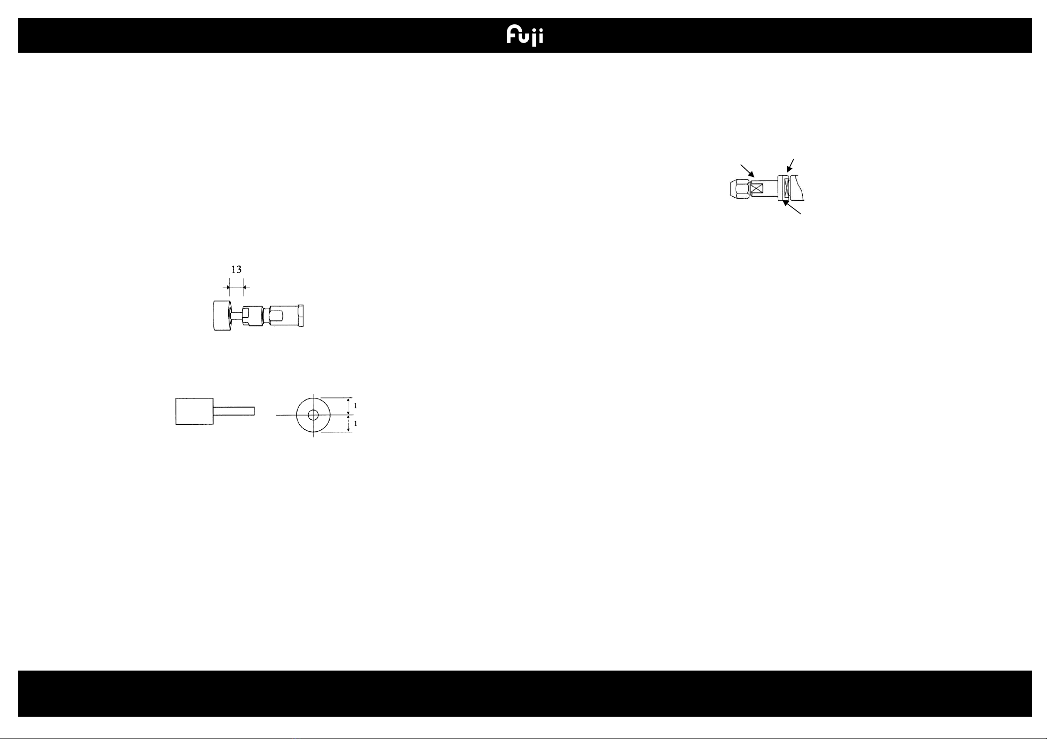
CORRECT WHEEL GUARD AND FLANGES FOR GRINDERS
Always use the recommended wheel guard and wheel flanges only and make sure that they are mounted in
the right places not too loose and not too tight when mounting the abrasive product to the grinder. Only trained
personnel who well know how to mount the abrasive product, the wheel guard and the flanges on the tool
must do this task.
Do not use a wheel guard and wheel flanges that are damaged, severely worn, nicked, bent, warped and
burred. Do not reform them.
CORRECT BACKING PAD AND FLANGES FOR SANDERS
Always use the recommended backing pad and flanges only and make sure that they are mounted in the right
places not too loose and not too tight when mounting the abrasive product to the sander. Only trained
personnel who well know how to mount the abrasive product on the tool must do this task.
Be sure to use a backing pad that fully supports the sanding disc over its diameter.
Do not use a backing pad and flanges that are damaged, severely worn, nicked, bent, warped and burred. Do
not reform them.
07/2017
4
5412060203 Rev.03

EN
Original instructions
MAXIMUM SPEEDS OF ABRASIVE PRODUCT AND TOOL
Be sure to check the speed of the spindle of the tool whenever mounting the abrasive product. Make sure that
the maximum allowable speed (rotational frequency) of the abrasive product is equal to or above the
maximum speed of the tool. Never use an abrasive product whose maximum allowable speed is lower than
the maximum speed of the tool. Remember that there are abrasive products on which the peripheral speed is
shown instead of the maximum allowable rotational frequency. Be sure to check the conversion table
converting the peripheral speed into the maximum allowable rotational frequency shown in the underpart of
this manual. Check the spindle thread.
COLLET CHUCK AND MOUNTED ABRASIVE FOR DIE GRINDERS
Make sure before attaching the mounted abrasive to the collet chuck that the shank of the mounted abrasive
is compatible with the collet chuck.
When using a mounted abrasive on the tool, make sure that the minimum gripping length of the collet chuck is
either the shank diameter plus 5 mm or a minimum of 10 mm whichever is the greater.
Try to keep the overhang under 13 mm. If the mounted abrasive shows an overhang greater than 13mm, the
speed of the tool should be lowered according to spindle overhang.
Make sure that the mounted abrasive rotates in a concentric way and that the run-out is correct.
Make sure that the shank of the mounted abrasive is straight and that the abrasive is securely fixed to the
shank.
Be sure to securely attach the shank of the mounted abrasive to the collet chuck.
When attempting to use any other inserted tool on the collet chuck, be sure to do so with care in accordance
with its manufacturer's instructions before use. If there should be any doubt about the safe and correct use,
consult its manufacturer or FUJI’s appointed distributor.
Make sure that the collet is not damaged and severely worn.
COLLET CHUCK AND TOOL SPINDLE
When attempting to use a collet chuck on a tool that is not originally designed for use with a collet chuck,
make sure that the spindle of the tool does not reach the bottom of the threaded hole of the collet chuck.
Check the length of the tool spindle and the depth of the threaded hole of the collet chuck before use. If the
spindle of the tool reaches the bottom of the threaded hole of the collet chuck, be sure to use a suitable
spacer between them.
Make sure that the threaded size of the collet chuck is compatible with the spindle thread size of the tool.
If there should be any doubt about the safe and correct use of the tool, be sure to consult the manufacturer
before attempting to use the collet chuck on the tool.
THREADED ABRASIVE PRODUCT AND TOOL SPINDLE
When attempting to use a threaded cup wheel, a threaded cone or a threaded plug on the tool, make sure that
the spindle of the tool does not reach the bottom of the threaded hole of the abrasive product. Check the
length of the tool spindle and the depth of the threaded hole of the abrasive product before use. If the spindle
of the tool reaches the bottom of the threaded hole of the abrasive product, be sure to use a suitable spacer
between them.
Make sure that the thread size of the abrasive product is compatible with the spindle thread size of the tool.
If there should be any doubt about the safe and correct use of the tool with the threaded abrasive products, be
sure to consult the manufacturer before attempting to use them on the tool.
TOOL WITH SPEED GOVERNOR
For grinders with a speed governor, check the rotational frequency (speed) of the tool regularly.
Make it a rule to check the speed before each use.
07/2017
5
5412060203 Rev.03
Collet chuck
Spindle thread
Spacer

EN
Original instructions
WHEEL SIZES OF ABRASIVE PRODUCT AND PERIPHERAL SPEED
The following table is a reference for Grinding Wheel Size / Peripheral speed / Maximum free speed. When
using abrasive product, on which the peripheral speed is shown instead of the maximum allowable free speed,
refer to this table.
Wheel diameter / Peripheral speed /Maximum free speed
Grinding wheel
diameter (mm)
Peripheral speed (m/min)
1800
2000
2400
2700
3000
3500
3800
4000
4300
4800
6
95493
106103
127324
143240
159155
185681
201596
212207
228122
254648
10
57296
63662
76394
85944
95493
111409
120958
127324
136873
152789
13
44074
48971
58765
66111
73456
85699
93045
97942
105287
117530
16
35810
39789
47747
53715
59683
69630
75599
79578
85546
95493
19
30156
33506
40208
45234
50259
58636
63662
67013
72039
80415
22
26044
28937
34725
39065
43406
50640
54981
57875
62215
69449
25
22918
25465
30558
34377
38197
44563
48383
50930
54749
61116
32
17905
19894
23873
26857
29842
34815
37799
39789
42773
47747
38
15078
16753
20104
22617
25130
29318
31831
33506
36019
40208
45
12732
14147
16977
19099
21221
24757
26880
28294
30416
33953
50
11459
12732
15279
17189
19099
22282
24192
25465
27375
30558
58
9879
10976
13171
14818
16464
19208
20855
21952
23599
26343
65
8815
9794
11753
13222
14691
17140
18609
19588
21057
23506
75
7639
8488
10186
11459
12732
14854
16128
16977
18250
20372
100
5730
6366
7639
8594
9549
11141
12096
12732
13687
15279
125
4584
5093
6112
6875
7639
8913
9677
10186
10950
12223
150
3820
4244
5093
5730
6366
7427
8064
8488
9125
10186
180
3183
3537
4244
4775
5305
6189
6720
7074
7604
8488
205
2795
3105
3727
4192
4658
5435
5900
6211
6677
7453
230
2491
2768
3321
3737
4152
4844
5259
5536
5951
6643
255
2247
2497
2996
3370
3745
4369
4743
4993
5368
5992
305
1879
2087
2505
2818
3131
3653
3966
4175
4488
5009
Maximum free speed(rpm)
MAXIMUM SPEED OF RUBBER BACKING PADS AND TOOL
The following table is a list of the maximum allowable rotational frequency (speed) of the rubber backing pads
for sanding discs. Make sure that the maximum allowable rotational frequency of the rubber backing pads are
equal to or above the maximum rotational frequency of the tool.
AC No.
D
t
d
Pin Specs
Maximum Rotation
Frequency (rpm)
ModeIs
mm
in
mm
in
mm
in
mm
RP-2-2
45
1 49/64
22.7
57/64
—
W3/8-16
with
Attachments
15,000
FA-2C-1, -1BF, FA-2CX-1, -1BF, FA-20-1F, FA-20X-1F * (A-122693-01)
FA-2C-2, 2CX-2, -2C-3, -2CX-3 Series, FA-20-2,-2F * (A-122693-03)
RP-3-2
76
3
10. 5
13/32
15.9
5/8
without Pin
13,500
FA-3CK-1
RP-4-3
100
4
12.0
15/32
15.9
5/8
34
1 11/32
13,500
FA-4C-1, -1F, FA-4CH-1
RP-4-5
100
4
17.0
43/64
22.2
7/8
46
1 13/16
10,000
FA-4CH-3, FA-4CHK-3
RP-5-3
127
5
17.0
43/64
22.2
7/8
44
1 47/64
8,500
FA-150K-20, -30
RP-5-5
127
5
17.0
43/64
22.2
7/8
46
1 13/16
8,500
FA-4CHK-3, FA-5C-5, FA-150KG-7, FA-5E-7 Series
RP-5-6
127
5
14.0
35/64
22.2
7/8
46
1 13/16
8,500
FA-5C-6, FA-5E-4 Series
RP-6
152
6
15.0
19/32
22.2
7/8
46
1 13/16
8,000
FA-180K-2R
RP-7
180
7
15.0
19/32
22.2
7/8
46
1 13/16
7,000
FA-5C-5, -7, FA-7C-13, FA-5E-6 Ser i es, FA-6C-9, -10
FA-5E-7V, 7E-1, 5, Series, FV-7-1M, 2M
FA-150KG-7, FA-45-9F,-10F
RP-9-1
230
9
15.0
19/32
22.2
7/8
46
1 13/16
5,900
FA-9C-2, -2M, -4, -4M, FV-9BH-1M
07/2017
6
5412060203 Rev.03

EN
Original instructions
HOW TO MOUNT ABRASIVE PRODUCT ON TOOL
PENCIL GRINDER FG-06-1
TURBO GRINDERS TURBO-100, TURBO-100A
1. Hold Spindle (438) or Chuck Body (346) with open-end
wrench.
2. Loosen Collet (342) with open-end wrench.
3. Mount the mounted abrasive on the tool.
4. Tighten Collet with the open-end wrenches.
PENCIL GRINDER FG-06S-1
1. Insert pin spanner through chuck body (346) and housing
holes to lock spindle.
2. Loosen collet nut (343) with 7mm open spanner.
3. Fit accessory in collet.
4. Tighten collet nut with open spanner.
5. Remove pin spanner to unlock spindle.
DIE GRINDERS
FG-13series
FG-26, -26L -26H, -26HL, -50, -50H series
FG-3H-5F, FG-2VX-1F, FG-3VX-1F, FG-3VX-6F series
FA-2C-2 and -3 , FA-20-2,-2F, FA-2C-30,FA-2CX-30 series
1. Hold Rotor (207) or Collet (342) with open-end wrench.
2. Loosen Collet (342) or Collet Nut (343) with open-end wrench.
3. Mount the mounted abrasive on the tool.
4. Tighten Collet or Collet Nut with the open-end wrenches.
DIE GRINDERS FG-12U, -25D and -50D series
1. Hold Spindle (441) with open-end wrench.
2. Loosen Collet Nut (343) with open-end wrench.
3. Mount the mounted abrasive on the tool.
4. Tighten Collet Nut with the open-end wrenches.
ALL STRAIGHT GRINDERS AND EXTENDED GRINDERS
1. Insert Wheel Flange (A) (303) on Spindle (301). Be sure to
mount the key groove of the flange in line with the key on
Spindle.
2. Insert Snap Ring (G02) on Spindle.
3. Mount the grinding wheel on Spindle.
4. Insert Wheel Flange (B) (304) on Spindle.
5. Hold Wheel Flange (A) with open-end wrench, and screw
F01 and F02 Nuts on Spindle with open-end wrench.
6. Mount Wheel Guard (335) on Spindle Bearing Cover (221)
and secure it with Bolt, Spring Washer and Nut provided with
the tool.
ALL ANGLE GRINDERS AND VERTICAL GRINDERS
MALE SPINDLE TYPE
1. Screw Wheel Flange (A) (303) on Spindle (301).
2. Mount the grinding wheel on Spindle.
3. Screw Wheel Flange (B) (304) on Spindle
4. Screw Detent Bolt (D35) into Spindle.
(No Detent Bolt is used for FA-5E,FA-45 series)
FEMALE SPINDLE TYPE
1. Insert Wheel Flange (B) (304) into the hole of the grinding
wheel and mount them on Wheel Flange (A) (303).
2. Screw Detent Bolt (321) into Spindle (301).
MOUNTING CUP WHEEL ON VERTICAL GRINDERS
1. Insert Cup Wheel Holder Flange (307) into the hole of the
cup wheel and mount them on Spindle.
2. Screw Detent Bolt (D35) into Spindle.
07/2017
7
5412060203 Rev.03
Grinding Wheel
Grinding Wheel
Grinding Wheel
Cup Wheel

EN
Original instructions
MOUNTING A SANDING DISC ON ANGLE SANDERS AND VERTICAL SANDERS
1. Mount Wheel Flange (A) (303) and Rubber Backing Pad (320) on Spindle (301).
2. Mount Sanding Disc on Spindle.
3. Mount Wheel Flange (B) (305) on Spindle.
4. Screw Detent Bolt (321) into Spindle.
(No Detent Bolt is used for FA-5E,FA-45 series)
Angle sander
Vertical sander
MOUNTING WIRE BRUSH ON ANGLE GRINDERS FA-6C,
FA-7C and FA-9C series
MALE SPINDLE TYPE
1. Mount Spacers (503) and (308) on Spindle (301).
2. Mount a wire brush on Spindle.
3. Screw Nut (F02) on Spindle to secure the wire brush to the
Spindle.
FEMALE SPINDLE TYPE
1. Mount Spacer (308) on Spindle (301).
2. Mount a wire brush on Spindle.
3. Screw Bolt (306) on Spindle to secure the wire brush to
Spindle.
DISC SANDER
1. Mount Paper Pad (320A, 320B) on Spindle (207).
2. Mount Sanding Disk on Spindle.
3. Maintain Wheel Flange (A) (303) with wrench.
4. Screw and tighten Wheel Flange (B) (305).
MOUNTING CUTTER ON FA-5E-8V, FA-6C-20, FA-7C-21
1. Insert Wheel Flange (B) (304) into the hole of the cutter and
mount it on Wheel Flange (A) (303).
2. Screw Detent Bolt (321) into Spindle (301).
3. Mount Wheel Guard (335) on Housing (201) and secure it
with Bolt, Spring Washer and Nut provided with the tool.
MOUNTING SANDING BELT ON BELT SANDERS
1. Open Protector (557) by pulling in the direction A, then B.
2. Place the Sanding Belt on Guide Roller (698) and press in
the direction C.
3. Place the Sanding Belt around Drive Roller (665) and slowly
release.
4. Close Protector by repeating operation 1 in the opposite
way.
5. Run the belt sander at low speed, and adjust the position of
the Sanding Belt on Guide Roller with Adjusting Screw (385).
07/2017
8
5412060203 Rev.03
Sanding disc
Sanding disc
Wire Brush
Wire Brush
Sanding disc
Cutter

EN
Original instructions
MANUFACTURER’S LIMITED WARRANTY
Limited Warranty: The “Products” of Fuji Industrial Technique Co.,Ltd. (“FUJI”) are warranted to be free
from defects in material and workmanship for one year from the date of purchase. This Warranty applies only
to Products purchased new from FUJI or its authorized dealers. Of course, this Warranty does not apply to
products which have been abused, misused, modified, or repaired by someone other than FUJI or its
Authorized Service Representatives. If a FUJI Product proves defective in material or workmanship within one
year after purchase, return it to any FUJI Factory Service Center or Authorized Service Center for FUJI tools,
transportation prepaid, enclosing your name and address, adequate proof of date of purchase, and a short
description of the defect. FUJI will, at its option, repair or replace defective Products free of charge. Repairs or
replacements are warranted as described above for the remainder of the original warranty period. FUJI’s sole
liability and your exclusive remedy under this Warranty is limited to repair or replacement of the defective
Product. (There Are No Other Warranties Expressed Or Implied And FUJI Shall Not Be Liable For Incidental,
Consequential, Or Special Damages, Or Any Other Damages, Costs Or Expenses Excepting Only The Cost
Or Expense Of Repair Or Replacement As Described Above.)
COPYRIGHT 2011, Fuji Industrial Technique Co.,Ltd.
All rights reserved. Any unauthorized use or copying of the contents or part thereof is prohibited. This applies
in particular to trademarks, model denominations, part numbers and drawings. Use only authorized parts. Any
damage or malfunction caused by the use of unauthorized parts is not covered by Warranty or Product
Liability.
07/2017
9
5412060203 Rev.03

JA
取扱説明書
取扱説明書
この製品は、研削、切断、研磨作業用に、研削用製品に取り付けて使用するように設計されています。各製品に取り付け可
能な研削用製品は、この説明書に記載されています。他の用途には使用しないでください。業務用製品です。
エアラインフィルタとルブリケータ
エアラインから水分とゴミを取り除き、注油をする必要があります。水分、ゴミ、他の不純物が製品に入ると、モータ部の停止、部
品の早期摩耗、性能低下を招くことがあります。エアフィルタとルブリケータは、できるだけ製品に近い場所に取り付けてください。
潤滑油
潤滑油が眼や口に入った場合は、直ちに医療手当てを受けてください。
エアラインルブリケータを使用していない場合は、毎日製品を使用する前に、モータ部に ISOVG32 タービン油もしくは同等品を
注油してください。注油後に最高速度で作動させないでください。オーバースピードになることがあります。ベアリング、カム、クラッ
チ部、ギア、ギアケースの潤滑油には、リチウム系のグリースをお勧めします。メンテナンスや定期点検のときに注油してください。
下記潤滑油をお勧めします。
モータ部品
Castrol Alphasyn T32
Mobil Mobil SHC 624
Texaco RD Lube 32
Kuwait Petroleum Q8 Schuman ISO VG32
Statoil Mereta 32
ベアリング、ギア、クラッチ、カム
BP Energrese LS-EP2
Castrol Spheerol EP L2
Esso Beacon 2
Shell Alvania Grease EP2
Mobil Mobilplex 47
Texaco Multifak EP2
Kuwait Petroleum Q8 Rembrandt EP
潤滑油を扱うときは、防油素材でできた衣服を着用してください。潤滑油で汚れた衣服は取り替えてください。
メンテナンスと修理
製品のメンテナンスやテストは、不二での講習を受け、合格した有資格者のみが実施できます。
使用中に異常を感じた場合は直ちに使用を中止して、点検・修理を依頼してください。不二または国内の正規代理店で、修
理やメンテナンスに関する情報を提供しています。
500 時間作動した後、または 6ヶ月毎に、製品をオーバーホールするようにお勧めします。部品取り換えの際は、必ず純正部
品を使用してください。類似代替品を使用すると性能が低下し、頻繁にメンテナンスが必要になります。
メンテナンスや修理の際は、必ずエアの供給を止め、製品をエアホースから外してください。
使用前には、ねじの緩みや部品の損傷等がないか、必ず点検してください。
スピードガバナのメンテナンスや修理の際は、間違いがないように注意してください。疑問がある場合には、不二の正規代理店や
修理工場に連絡し、正しい情報を入手してください。スピードガバナのメンテナンスや修理に間違いがあると、大きな事故を引き
起こすことがあります。修理やメンテナンスを実施した後は、スピードガバナが正しく作動し、回転速度が製品に表示されている
最高回転速度以下であることを必ず確認してください。
使用後の製品管理
必要なときにいつでも安全に使用できるように、製品の管理をしてください。
使用後の製品は、安全な状態で保管してください。
製品の処分
製品には鋼鉄、鋳造鉄、真ちゅう、銅、アルミ合金、ゴム、プラスチックなどが使用されています。製品を処分する際は、人体や
環境に汚染の影響がでないように配慮してください。
グラインダの適正砥石カバーと適正砥石フランジ
研削用製品を取り付けるときは、必ず推奨砥石カバーと砥石フランジを、正しい場所に適切な締付力で取り付けてください。研
削用製品、砥石カバー、砥石フランジを製品に取り付ける方法を熟知している、訓練された担当者が取り付けてください。
砥石カバーや砥石フランジに損傷やキズがあったり、過度に磨耗していたり、曲がったり、歪んでいたり、割れ目がある場合は絶
対に使用しないでください。また、砥石カバーや砥石フランジを改造しないでください。
サンダの適正バッキングパッドと適正フランジ
研削用製品を取り付けるときは必ず推奨バッキングパッドとフランジを使い、正しい場所に適切な締付力で取り付けてください。
研削用製品を製品に取り付ける方法を熟知している、訓練された担当者が取り付けてください。
サンディングディスクを保持するためのバッキングパッドが装着されていることを確認してください。
バッキングパッドに損傷やキズがあったり、過度に磨耗していたり、曲がったり、歪んでいたり、割れ目がある場合は絶対に使用し
ないでください。また、バッキングパッドを改造しないでください。
07/2017
10
5412060203 Rev.03

JA
取扱説明書
研削用製品と製品の最高回転速度
研削用製品を装着するときは、製品のスピンドル回転速度を必ず測定してください。研削用製品の最高許容回転速度 (回転
数) が、製品の最高回転速度と同じかそれ以上であることを確認してください。最高許容回転速度が、製品の最高回転速度
以下の研削製品は絶対に使用しないでください。研削用製品によっては、最高許容回転数の代わりに周速度を表示したもの
があるので、注意してください。この説明書にある周速度を最高許容回転数に換算する表を参照してください。スピンドルスレッ
ドをチェックしてください。
ダイグラインダ用コレットチャックと軸付砥石
軸付砥石をコレットチャックに装着する前に、軸付砥石の軸がコレットチャックに適合していることを確認してください。
製品で軸付砥石を使うときは、コレットチャックの最小挿入長さが、軸直径 + 5 mm または最低で 10 mm のどちらか大きい方
になることを確認してください。
オーバーハングは 13 mm 以下に維持してください。軸付砥石のオーバーハングが 13 mm 以上の場合は、製品の回転速度を
スピンドルのオーバーハングにあわせて下げてください。
軸付砥石が同心回転し、逃げが適切であることを確認してください。
軸付砥石の軸がまっすぐで、砥石が軸にしっかり取り付けてあることを確認してください。
軸付砥石の軸はコレットチャックにしっかり取り付けてください。
他の軸付砥石をコレットチャックに取り付けて使用するときは、必ずそのメーカーの指示に従ってください。安全で正しい使用法に
関して疑問がある場合には、メーカーまたは不二の正規代理店に連絡してください。
コレットに損傷がなく、極度に磨耗されていないことを確認してください。
コレットチャックと製品のスピンドル
コレットチャックを付けて使うように設計されていない製品にコレットチャックを取り付けて使用するときは、製品のスピンドルがコレッ
トチャックのねじを切った穴底に接触しないことを確認してください。使用前に、製品のスピンドルの長さとコレットチャックのねじ穴
の深さを測定してください。製品のスピンドルがコレットチャックのねじを切った穴底に接触するようなら、当社指定の適切なスペー
サを間に入れてください。
コレットチャックのねじ寸法が、製品のスピンドルのねじ寸法に合うことを確認してください。
製品の安全で正しい使用法に関して疑問がある場合には、コレットチャックを製品に付ける前に、当社に必ずご相談ください。
ねじ付研削製品と製品のスピンドル
ねじ付カップ砥石、ねじ付コーン型砥石、またはねじ付プラグを製品に付けて使用するときは、製品のスピンドルが研削製品のね
じ切り穴底に接触しないようにしてください。使用前に、製品のスピンドルの長さと研削製品のねじ穴の深さを測定してください。
製品のスピンドルが研削製品のねじを切った穴底に接触するようなら、当社指定の適切なスペーサを間に入れてください。
研削製品のねじ寸法が、製品のスピンドルのねじ寸法に合うことを確認してください。
ねじ切り研削製品が付いた製品の安全で正しい使用法に関して疑問がある場合には、製品に付ける前に、当社に必ずご相
談ください。
スピードガバナ付製品
スピードガバナ付グラインダは、製品の回転数 (速度) を定期的にチェックしてください。
使用前には必ず、回転速度を確認してください。
07/2017
11
5412060203 Rev.03
コレットチャック
スピンドルスレッド
スペーサ

JA
取扱説明書
先端研削工具の直径と周速度、回転速度
次の表は、先端研削工具(トイシなど)の直径:周速度:回転速度の関係を示しています。最高許容回転速度のかわりに周
速度を表示した先端研削工具を使うときは、この表を参照してください。
先端工具直径 / 週速度 / 最高フリー速度
先端工具
直径 (mm)
周速度 (m/min)
1800
2000
2400
2700
3000
3500
3800
4000
4300
4800
6
95493
106103
127324
143240
159155
185681
201596
212207
228122
254648
10
57296
63662
76394
85944
95493
111409
120958
127324
136873
152789
13
44074
48971
58765
66111
73456
85699
93045
97942
105287
117530
16
35810
39789
47747
53715
59683
69630
75599
79578
85546
95493
19
30156
33506
40208
45234
50259
58636
63662
67013
72039
80415
22
26044
28937
34725
39065
43406
50640
54981
57875
62215
69449
25
22918
25465
30558
34377
38197
44563
48383
50930
54749
61116
32
17905
19894
23873
26857
29842
34815
37799
39789
42773
47747
38
15078
16753
20104
22617
25130
29318
31831
33506
36019
40208
45
12732
14147
16977
19099
21221
24757
26880
28294
30416
33953
50
11459
12732
15279
17189
19099
22282
24192
25465
27375
30558
58
9879
10976
13171
14818
16464
19208
20855
21952
23599
26343
65
8815
9794
11753
13222
14691
17140
18609
19588
21057
23506
75
7639
8488
10186
11459
12732
14854
16128
16977
18250
20372
100
5730
6366
7639
8594
9549
11141
12096
12732
13687
15279
125
4584
5093
6112
6875
7639
8913
9677
10186
10950
12223
150
3820
4244
5093
5730
6366
7427
8064
8488
9125
10186
180
3183
3537
4244
4775
5305
6189
6720
7074
7604
8488
205
2795
3105
3727
4192
4658
5435
5900
6211
6677
7453
230
2491
2768
3321
3737
4152
4844
5259
5536
5951
6643
255
2247
2497
2996
3370
3745
4369
4743
4993
5368
5992
305
1879
2087
2505
2818
3131
3653
3966
4175
4488
5009
最高フリー速度 (rpm)
ゴム製バッキングパッドと製品の最高回転速度
次の表は、サンディングディスク用ゴム製バッキングパッドの最高許容回転数 (速度) のリストです。ゴム製バッキングパッドの最高
許容回転数 が、製品の最高回転数と同じかそれ以上であることを確認してください。
D
t
d
ピン仕様
最高回転数 (rpm)
モデル
mm
in
mm
in
mm
in
mm
RP-2-2
45
1 49/64
22.7
57/64
—
W3/8-16
付属品付き
15,000
FA-2C-1, -1BF, FA-2CX-1, -1BF FA-20-1F, FA-20X-1F* (A-122693-01)
FA-2C-2, 2CX-2, -2C-3, -2CX-3 Series, FA-20-2,-2F * (A-122693-03)
RP-3-2
76
3
10. 5
13/32
15.9
5/8
ピン無し
13,500
FA-3CK-1
RP-4-3
100
4
12.0
15/32
15.9
5/8
34
1 11/32
13,500
FA-4C-1, -1F, FA-4CH-1
RP-4-5
100
4
17.0
43/64
22.2
7/8
46
1 13/16
10,000
FA-4CH-3, FA-4CHK-3
RP-5-3
127
5
17.0
43/64
22.2
7/8
44
1 47/64
8,500
FA-150K-20, -30
RP-5-5
127
5
17.0
43/64
22.2
7/8
46
1 13/16
8,500
FA-4CHK-3, FA-5C-5, FA-150KG-7, FA-5E-7 Series
RP-5-6
127
5
14.0
35/64
22.2
7/8
46
1 13/16
8,500
FA-5C-6, FA-5E-4 Series
RP-6
152
6
15.0
19/32
22.2
7/8
46
1 13/16
8,000
FA-180K-2R
RP-7
180
7
15.0
19/32
22.2
7/8
46
1 13/16
7,000
FA-5C-5, -7, FA-7C-13, FA-5E-6 Ser i es, FA-6C-9, -10
FA-5E-7V, 7E-1, 5, Series, FV-7-1M, 2M
FA-150KG-7, FA-45-9F,-10F
RP-9-1
230
9
15.0
19/32
22.2
7/8
46
1 13/16
5,900
FA-9C-2, -2M, -4, -4M, FV-9BH-1M
07/2017
12
5412060203 Rev.03

JA
取扱説明書
先端研削工具の製品への取り付け方法
ペンシルグラインダ FG-06-1
ターボグラインダ TURBO-100、TURBO-100A
1. 片口スパナでスピンドル (438) またはチャックボディ (346) を押さえる。
2. 片口スパナでコレット (342) を緩める。
3. 軸付トイシを製品に取り付ける。
4. 片口スパナでコレットを締める。
ペンシルグラインダ FG-06S-1
1. チャックボディ (346) と本体部のピン穴を合わせ、ピンスパナを通して
チャックボディを保持する。
2. コレットナット (343) を7mm 片口スパナでゆるめる。
3. ロータリーバー又は軸付トイシをツールに取り付ける。
4. コレットナット (343) を片口スパナで締める。
5. ピンスパナを抜く。
ダイグラインダ
FG-13 シリーズ
FG-26、-26L, -26H, -26HL, -50, -50Hシリーズ
FG-3H-5F、FG-2VX-1F、FG-3VX-1F、FG-3VX-6F シリーズ
FA-2C-2、-3、FA-20-2,-2F,FA-2C-30、FA-2CX-30 シリーズ
1. 片口スパナでロータ (207)またはコレット (342) を押さえる。
2. 片口スパナでコレット (343) またはコレットナット (343)を緩める。
3. 軸付トイシを製品に取り付ける。
4. 片口スパナで、コレットまたはコレットナットを締める。
ダイグラインダ FG-12U、-25D、-50D シリーズ
1. 片口スパナでスピンドル (441) を押さえる。
2. 片口スパナでコレットナット (343) を緩める
3. 軸付トイシを製品に取り付ける。
4. 片口スパナでコレットナットを締める。
全ストレートグラインダとエクステンショングラインダ
1. 砥石フランジ (A) (303) をスピンドルに (301) 挿入する。フランジのキー
溝が、スピンドルのキーと直線上になるようにして取り付ける。
2. スナップリング (G02) をスピンドルに挿入する。
3. 平トイシをスピンドルに取り付ける。
4. 砥石フランジ (B) (304) をスピンドルに挿入する。
5. 砥石フランジ (A) を片口スパナで押さえ、F01 とF02 ナットを片口スパ
ナでスピンドルに締めて取り付ける。
6. 砥石カバー (335) をスピンドルベアリングカバー (221) に取り付け、ボル
ト、スプリングワッシャ、ナットで製品に締付けて固定する。
全アングルグラインダとバーチカルグラインダ
オス型スピンドルタイプ
1. 砥石フランジ (A) (303) をスピンドル (301) に回して留める。
2. 砥石車をスピンドルに取り付ける。
3. 砥石フランジ (B) (304) をスピンドルに回して留める。
4. 砥石押えボルト (D35) をスピンドルに回して留める。
(FA-5E, FA-45 シリーズには砥石押えボルトは使わない)
メス型スピンドルタイプ
1. 砥石フランジ (B) (304) を砥石車の穴に挿入し、それを砥石フランジ
(A) (303) に取り付ける。
2. 砥石押えボルト (321) をスピンドル (301) に回して留める。
カップ砥石をバーチカルグラインダに取り付ける
1. カップ砥石ホルダフランジ (307) をカップ砥石の穴に挿入し、それをス
ピンドルに取り付ける。
2. 砥石押えボルト (D35) をスピンドルに回して留める。
07/2017
13
5412060203 Rev.03
平トイシ
トイシ
カップ砥石
トイシ
(TURBO)
(FG-06-1)
(FG-13シリーズ)

JA
取扱説明書
サンディングディスクをアングルサンダやバーチカルサンダに取り付ける
1. 砥石フランジ (A) (303) とゴム製バッキングパッド (320) を、スピンドル (301) に取り付ける。
2. サンディングディスクをスピンドルに取り付ける。
3. 砥石フランジ (B) (305) をスピンドルに取り付ける。
4. 砥石押えボルト (321) をスピンドルに回して留める。
(FA-5E, FA-45 シリーズには砥石押えボルトは使わない)
アングルサンダ
バーチカルサンダ
ワイヤブラシをアングルグラインダ FA-6C、FA-7C、FA-9C シリーズに取
り付ける
オス型スピンドルタイプ
1. スペーサ (503) と(308) をスピンドル (301) に取り付ける。
2. ワイヤブラシをスピンドルに取り付ける。
3. ナット (F02) をスピンドルに回して入れ、ワイヤブラシをスピンドルに固
定する。
メス型スピンドルタイプ
1. スペーサ (308) をスピンドル (301) に取り付ける。
2. ワイヤブラシをスピンドルに取り付ける。
3. ボルト (306) をスピンドルに回して入れ、ワイヤブラシをスピンドルに固
定する。
ディスクサンダ
1. ペーパーパッド (320A、320B) をスピンドル (207) に取り付ける。
2. サンディングディスクをスピンドルに取り付ける。
3. 砥石フランジ (A) (303) をレンチで押える。
4. 砥石フランジ (B) (305) を回して締める。
アングルグラインダへのダイヤモンドカッタの取付方法
(FA-5E-8V、FA-6C-20、FA-7C-21)
1. 砥石フランジ (B) (304) をカッタの穴に挿入し、それを砥石フランジ
(A) (303) に取り付ける。
2. 砥石押えボルト (321) をスピンドル (301) に回して留める。
3. 砥石カバー (335) を本体 (201) に取り付け、ボルト、スプリングワッ
シャ、ナットでしっかりと締付けて固定する。
サンディングベルトのベルトサンダへの取付方法
1. プロテクタ (557) をまず A の方向に引っ張り、それから B の方向に引
っ張って、プロテクタを開ける。
2. サンディングベルトをガイドローラ (698) に引っかけ、Cの方向に押しつ
ける。
3. サンディングベルトをドライブローラ (665) に引っかけ、ゆっくり離す。
4. ステップ 1を逆にして繰り返し、プロテクタを閉める。
5. ベルトサンダを低速で回転させ、ガイドローラに対してサンディングベル
トが正しい位置になるように、調整ねじ (385) で調整する。
07/2017
14
5412060203 Rev.03
ワイヤブラシ
サンディングディスク
カッタ
サンディングディスク
サンディングディスク
ワイヤブラシ

JA
取扱説明書
保証内容と期間
保証内容:Fuji Industrial Technique Co.,Ltd. (不二空機株式会社/ 以下”不二”) の「製品」は、ご購入の日から 1年
間保証されています。この保証は、不二またはその認定代理店から新品購入された製品にのみに適用されます。この保証は、
不正使用、誤用、または改造使用、あるいは不二または認定サービスセンター以外によって修理された製品には適用されませ
ん。万一、ご購入後 1年以内に製品に素材や製造上の欠陥等があった場合は、不二または不二製品の認定サービスセンタ
ーまで、送料前払いでご返送ください。製品と一緒に、お客様のお名前、ご住所、(領収書など)ご購入日を証明できるものと
不具合の簡単な説明書きをご同梱ください。不二にて検査を行い、欠陥確認後、無償にて修理または交換いたします。
不二のお客様への保証賠償は、欠陥製品の修理または交換のみです。(この保証内容以外には、明示または黙示の保証は
ありません。不二は、偶発的、間接的、または特別な損害や他の損害、または上記の修理や交換にかかる費用や経費以外の
費用または経費に対し、責任を負いません。)
著作権 2011, Fuji Industrial Technique Co.,Ltd.
版権所有。ここに記載されているもの、またはその一部を許可なく使用・複写することは禁じられています。これは特に商標、モ
デルの種類、部品番号、図などに適用されます。認可された部品のみを使ってください。非認可部品の使用が原因による損傷
や故障は、保証や製造物責任の対象になりません。
07/2017
15
5412060203 Rev.03

ZH
原始说明
使用说明手册
本产品旨在与砂磨产品一起用于打磨、切割或砂光、抛光材料。用于每件工具的砂磨产品见本手册中以下说
明。不得用于其它目的。只供专业人员使用。
空气管线过滤器和润滑器
必须去除空气管线中的水汽和污物并予以适当润滑。如果水汽、污物和/或杂质进入工具中,可造成马达零件停
止转动、不必要的磨损及降低性能。空气过滤器和空气润滑器的安装建议尽可能接近使用中的工具。
润滑剂
如果任何润滑剂进入眼睛或误被摄入,请立即就医。如果空气管线润滑器不在使用,请在使用前每天用
ISOVG32 涡轮机油或相当等级的机油润滑马达零件。请勿在润滑后猛然加到全速,否则会造成超速运转。推荐
采用锂基润滑脂润滑轴承、凸轮以及离合器零件、齿轮和齿轮盒。请在维护或定期检查时润滑上述部件。以下
为推荐使用的润滑脂。
马达零件
Castrol Alphasyn T32
Mobil Mobil SHC 624
Texaco RD Lube 32
Kuwait Petroleum Q8 Schuman ISO VG32
Statoil Mereta 32
轴承、齿轮、离合器和凸轮
BP Energrese LS-EP2
Castrol Spheerol EP L2
Esso Beacon 2
Shell Alvania Grease EP2
Mobil Mobilplex 47
Texaco Multifak EP2
Kuwait Petroleum Q8 Rembrandt EP
经常操作润滑剂时,请穿戴由不透水材料制作的的适当衣服。被润滑剂污染的衣服应即更换。
维护和修理
工具必须由具有能力及经过训练的人员进行适当的维护和测试。如果出现任何故障或异常现象,应将工具停止
使用,进行检修。如有必要,可以从您所在国家的制造商或制造商授权代理处得到必要的修理与维护信息和说
明。建议使用 500 小时后或每六个月拆开工具检修及定期清洁。更换零件时,请确定使用真正的 Fuji Air Tools
原厂生产的更换零件。如果不这样做,可导致性能下降和增加维护。进行维护或修理时,请确定工具已从空气
管线脱开,或关断空气管线。
在工具准备使用之前,请确定各部件装配正确,所有紧固件都已上紧。
对速度控制器进行维护或修理时,一定要正确操作,不能有任何差错。如果有任何怀疑,一定要咨询 FUJI 的指
定经销商和修理厂并得到适当的信息。速度控制器修理过程中的任何一个失误均可造成严重事故。每次修理服
务和保养后一定要检查速度控制器是否工作正常,工具自由运转速度是否低于工具上所规定的对大速度。
工具用后保养
任何时候都要保持工具清洁,以便在必要时正确及安全使用。
工具用后存放时,应以安全的方式保存。
工具弃置
本工具用钢、铸铁、黄铜、青铜、铝合金、橡胶和塑料部件或上述材料制成。弃置工具时,不得对人类和环境
造成污染。
砂轮机正确的砂轮护罩和法兰接头
任何时候只能使用推荐的砂轮护罩和砂轮法兰接头。将砂磨产品安装在砂轮机上时,一定要保证它们安装在正
确的位置,不能太松,也不能太紧。只能由经过训练,真正了解如何将砂磨产品、砂轮护罩和法兰安装在工具
上的人员来执行此项任务。
切勿使用损坏、严重磨损、缺口、弯曲、卷边和有毛刺的砂轮护罩和砂轮法兰接头。切勿改造护罩和法兰。
砂光机正确的衬板和法兰
任何时候只能使用推荐的衬板和法兰接头。将砂磨产品安装在砂磨机上时,一定要保证它们安装在正确的位
置,不能太松,也不能太紧。只能由经过训练,真正了解如何将砂磨产品安装在工具上的人员来执行此项任
务。
一定要确保使用的衬板完全能够支持直径大于衬板直径的砂磨盘。
切勿使用损坏、严重磨损、缺口、弯曲、卷边和有毛刺的衬板和法兰接头。切勿改造衬板和法兰。
07/2017
16
5412060203 Rev.03

ZH
原始说明
砂磨产品和工具的最大速度
安装砂磨产品时一定要检查工具转轴的速度。请确认砂磨产品的最大允许速度(旋转频率)与工具最大速度相
等或大于工具最大速度。任何情况下郡不得使用其最大允许速度低于工具最大速度的砂磨产品。请注意,有些
砂磨产品上显示的是周缘速度而非最大允许旋转频率。请务必查看本手册下面提供的周缘速度 - 最大允许旋转
频率换算表。检查转轴螺纹
砂轮机夹头和安装砂磨产产品
在将砂磨工具安装到夹头上之前,请确认砂磨工具的轴与夹头匹配。
在工具上使用砂磨工具时,要确保夹头最小夹紧长度必须为砂磨工具颈轴直径再加 5 mm 或至少为 10 mm,
以两者中较大数值为准。
颈轴超出夹具部分应保持在 13 mm 以下。如果超出颈轴长度大于 13 mm,则工具速度应根据转轴超出长度降
低。
确保砂磨工具的旋装呈同心圆状,摆差正确。
确定砂磨工具的颈轴平直,砂磨工具在颈轴上安装紧固。
确定砂磨工具颈轴与夹头安装牢固。
在将任何其它工具插入夹头时,在使用前必须按照说明小心操作。如果对安全和正确使用有任何怀疑,请咨询
制造厂商或 FUJI 指定经销商。
确认夹头未经损坏或严重磨损.
夹头和工具转轴
如果试图在原先设计并非与夹头一起使用的工具上使用夹头,请注意不要让工具转轴碰到夹头螺纹孔的底部。
使用前请检查工具转轴的长度和夹头螺纹孔的深度。如果工具转轴达到夹头螺纹孔底部,一定要在它们之间放
上垫片。
夹头螺纹孔大小一定要与工具转轴螺纹直径匹配。
如果对安全和正确使用有任何怀疑,请在试图在工具上使用夹头之前先咨询制造厂商。
螺纹砂磨产品和工具转轴
如果试图在工具上使用螺纹杯形砂轮、螺纹锥形砂轮或螺纹柱塞,请确定工具转轴不可触及砂轮产品螺纹孔的
底部。使用前请检查工具转轴的长度和砂磨产品螺纹孔的深度。如果工具转轴触及砂磨产品螺纹孔底部,一定
要在它们之间放上垫片。
砂磨产品的螺纹孔大小一定要与工具转轴螺纹直径匹配。
如果对安全和正确使用有任何怀疑,请在试图在工具上使用螺纹砂磨产品之前先咨询制造厂商。
带速度控制器的工具
如果使用带速度控制器的砂轮机,请经常检查工具的旋转频率(速度)。
把使用前检查速度订为一项制度。
07/2017
17
5412060203 Rev.03
弹簧夹头
转轴螺纹
垫片

ZH
原始说明
砂磨产品砂轮尺寸和周边速度
下表是有关砂轮大小/周边速度/最大自由速度的参考资料。如果使用的砂磨产品上显示的是周边速度而不是最大
允许自由速度,请参考此表。
砂轮直径/周边速度/最大自由速度
砂轮直径(mm)
周边速度 (m/min)
1800
2000
2400
2700
3000
3500
3800
4000
4300
4800
6
95493
106103
127324
143240
159155
185681
201596
212207
228122
254648
10
57296
63662
76394
85944
95493
111409
120958
127324
136873
152789
13
44074
48971
58765
66111
73456
85699
93045
97942
105287
117530
16
35810
39789
47747
53715
59683
69630
75599
79578
85546
95493
19
30156
33506
40208
45234
50259
58636
63662
67013
72039
80415
22
26044
28937
34725
39065
43406
50640
54981
57875
62215
69449
25
22918
25465
30558
34377
38197
44563
48383
50930
54749
61116
32
17905
19894
23873
26857
29842
34815
37799
39789
42773
47747
38
15078
16753
20104
22617
25130
29318
31831
33506
36019
40208
45
12732
14147
16977
19099
21221
24757
26880
28294
30416
33953
50
11459
12732
15279
17189
19099
22282
24192
25465
27375
30558
58
9879
10976
13171
14818
16464
19208
20855
21952
23599
26343
65
8815
9794
11753
13222
14691
17140
18609
19588
21057
23506
75
7639
8488
10186
11459
12732
14854
16128
16977
18250
20372
100
5730
6366
7639
8594
9549
11141
12096
12732
13687
15279
125
4584
5093
6112
6875
7639
8913
9677
10186
10950
12223
150
3820
4244
5093
5730
6366
7427
8064
8488
9125
10186
180
3183
3537
4244
4775
5305
6189
6720
7074
7604
8488
205
2795
3105
3727
4192
4658
5435
5900
6211
6677
7453
230
2491
2768
3321
3737
4152
4844
5259
5536
5951
6643
255
2247
2497
2996
3370
3745
4369
4743
4993
5368
5992
305
1879
2087
2505
2818
3131
3653
3966
4175
4488
5009
最大自由速度(每分钟转数)
橡胶衬板和工具的最大速度
下表列出砂磨盘橡胶衬板的最大允许旋转频率(速度)。请确定橡胶衬板的最大允许旋转频率相等或超过工具
最大旋转频率。
AC No.
D
t
d
插销规格
最大旋转频率 (rpm)
型号
mm
in
mm
in
mm
in
mm
RP-2-2
45
1 49/64
22.7
57/64
—
W3/8-16
带附件
15,000
FA-2C-1, -1BF, FA-2CX-1, -1BF, FA-20-1F, FA-20X-1F * (A-122693-01)
FA-2C-2, 2CX-2, -2C-3, -2CX-3 Series, FA-20-2,-2F * (A-122693-03)
RP-3-2
76
3
10. 5
13/32
15.9
5/8
无插销
13,500
FA-3CK-1
RP-4-3
100
4
12.0
15/32
15.9
5/8
34
1 11/32
13,500
FA-4C-1, -1F, FA-4CH-1
RP-4-5
100
4
17.0
43/64
22.2
7/8
46
1 13/16
10,000
FA-4CH-3, FA-4CHK-3
RP-5-3
127
5
17.0
43/64
22.2
7/8
44
1 47/64
8,500
FA-150K-20, -30
RP-5-5
127
5
17.0
43/64
22.2
7/8
46
1 13/16
8,500
FA-4CHK-3, FA-5C-5, FA-150KG-7, FA-5E-7 Series
RP-5-6
127
5
14.0
35/64
22.2
7/8
46
1 13/16
8,500
FA-5C-6, FA-5E-4 Series
RP-6
152
6
15.0
19/32
22.2
7/8
46
1 13/16
8,000
FA-180K-2R
RP-7
180
7
15.0
19/32
22.2
7/8
46
1 13/16
7,000
FA-5C-5, -7, FA-7C-13, FA-5E-6 Ser i es, FA-6C-9, -10
FA-5E-7V, 7E-1, 5, Series, FV-7-1M, 2M
FA-150KG-7, FA-45-9F,-10F
RP-9-1
230
9
15.0
19/32
22.2
7/8
46
1 13/16
5,900
FA-9C-2, -2M, -4, -4M, FV-9BH-1M
07/2017
18
5412060203 Rev.03

ZH
原始说明
如何在工具上安装砂磨产品
铅笔型砂轮机 FG-06-1
涡轮式砂轮机 TURBO-100, TURBO-100A
1. 用开口扳手夹住转轴 (438) 或夹头杆部 (346) 。
2. 用开口扳手松开夹头 (342) 。
3. 将砂磨工具装上工具。
4. 用开口扳手上紧夹头。
铅笔型砂轮机 FG-06S-1
1. 卡盘体(346)与主体部的销孔对齐,将带销扳手传入其中,将卡盘体固定。
2. 用7mm 单头呆扳手将套筒螺母(343)松开。
3. 将带有转杆或轴的磨石安装在刀具上。
4. 用单头呆扳手将套筒螺母拧紧。
5. 将带销扳手拉出。
模具砂轮机
FG-13 系列,FG-26, -26L -26H, -26HL, -50, -50H 系列
FG-3H-5F, FG-2VX-1F, FG-3VX-1F, FG-3VX-6F 系列
FA-2C-2 和-3, FA-20-2,-2F, FA-2C-30, FA-2CX-30 系列
1. 用开口扳手夹住转子 (207) 或夹头(342) 。
2. 用开口扳手松开夹头 (342) 或夹头螺母 (343) 。
3. 将砂磨工具装上工具。
4. 用开口扳手上紧夹头或夹头螺母。
模具砂轮机 FG-12U, -25D and -50D 系列
1. 用开口扳手夹住转轴 (441) 。
2. 用开口扳手松开螺母 (343) 。
3. 将砂磨工具装上工具。
4. 用开口扳手上紧夹头螺母。
所有平直砂轮机和加长砂轮机
1. 将砂轮法兰 (A) (303) 插在转轴 (301)上。一定要将法兰的键槽对准
转轴上的键条。
2. 将卡环(G02) 插到转轴上。
3. 将砂轮插到转轴上。
4. 将砂轮法兰 (B) (304) 插到转轴上。
5. 用开口扳手夹住砂轮法兰(A) 并将螺丝 F01 和螺母 F02 装上转轴。
6. 将砂轮护罩 (335) 装上转轴轴承盖 (221) 并用随工具一起提供的螺
栓、弹簧垫片和螺母固定。
所有角度砂轮机和垂直砂轮机
公转轴型号
1. 用开口扳手(A) (303) 拧到转轴 (301)上。
2. 将砂轮装上转轴。
3. 用开口扳手(B) (304) 拧上转轴。
4. 将Detent 螺栓 (D35) 拧入转轴。
(FA-5E, FA-45 系列不用 Detent 螺栓)
母转轴型号
1. 将砂轮法兰 (B) (304) 插入砂轮孔中并将它们装上砂轮法兰
(A) (303)。
2. 将Detent Bolt (321) 拧入转轴(301)。
将杯式砂轮装在垂直砂轮机上
1. 将杯式砂轮支撑器法兰(307) 插入杯式砂轮的孔中并将它们装
上转轴。
2. 将Detent 螺栓 (D35) 插入转轴。
07/2017
19
5412060203 Rev.03
砂轮
砂轮
砂轮
杯形砂轮

ZH
原始说明
将砂磨盘安装在角度砂光机和垂直砂光机上
1. 将砂轮法兰 (A) (303) 和橡胶衬板 (320) 撞到转轴 (301)上。
2. 将砂磨盘装上转轴。
3. 将砂轮法兰(B) (305) 装上转轴。
4. 将Detent 螺栓 (321) 拧入转轴。
(FA-5E, FA-45 系列不用 Detent 螺栓)
角度砂光机
垂直砂光机
在角度砂轮机 FA-6C, FA-7C 和FA-9C 系列上安装钢丝刷
公转轴型号
1. 将垫片 (503) 和(308) 装上转轴 (301)。
2. 将钢丝刷装上转轴。
3. 将螺母 (F02) 拧上转轴以将钢丝刷固定在转轴上。
母转轴型号
1. 将垫片 (308) 装上转轴(301)。
2. 将钢丝刷装上转轴。
3. 将螺栓 (306) on 拧上转轴以将钢丝刷固定在转轴上。
盘式砂光机
1. 将砂纸衬板 (320A, 320B) 装上转轴 (207)。
2. 将砂光盘装上转轴。
3. 用扳手持住砂轮法兰(A) (303) 。
4. 拧上砂轮法兰(B) (305)并紧固。
将切割器装上 FA-5E-8V, FA-6C-20, FA-7C-21
1. 将砂轮法兰 (B) (304) 插入切割器孔眼并将其装上砂轮法兰
(A) (303)。
2. 将Detent 螺栓 (321) 拧入转轴 (301)。
3. 随工具提供的螺栓、弹簧垫片和螺母将砂轮护罩 (335) 装上
外壳 (201) 。
将磨砂带装上砂光机
1. 先往 A方向,然后往 B放下拉,打开保护罩 (557) 。
2. 将砂纸带放在导向滚筒(698) 上并往 C方向按压。
3. 将砂纸带绕过驱动滚筒(665) 并慢慢释放。
4. 以逆向顺序操作步骤 1,关上保护罩。
5. 以低速运行砂磨带,用调节螺丝(385) 调整砂磨带在导向滚筒
上的位置。
07/2017
20
5412060203 Rev.03
磨光盘
磨光盘
钢丝刷
钢丝刷
磨光盘
切割片
This manual suits for next models
28
Table of contents
Languages:
Other FujiFilm Grinder manuals