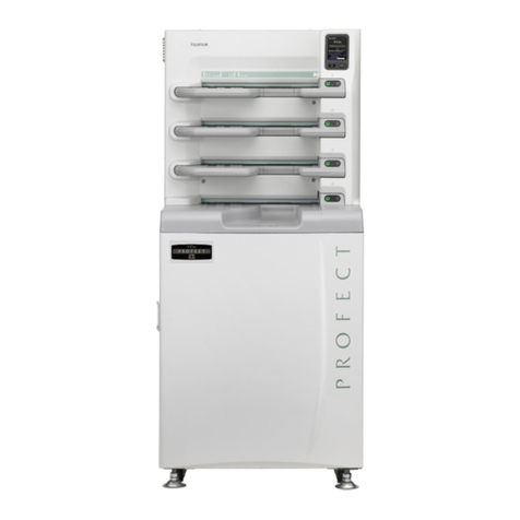
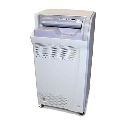
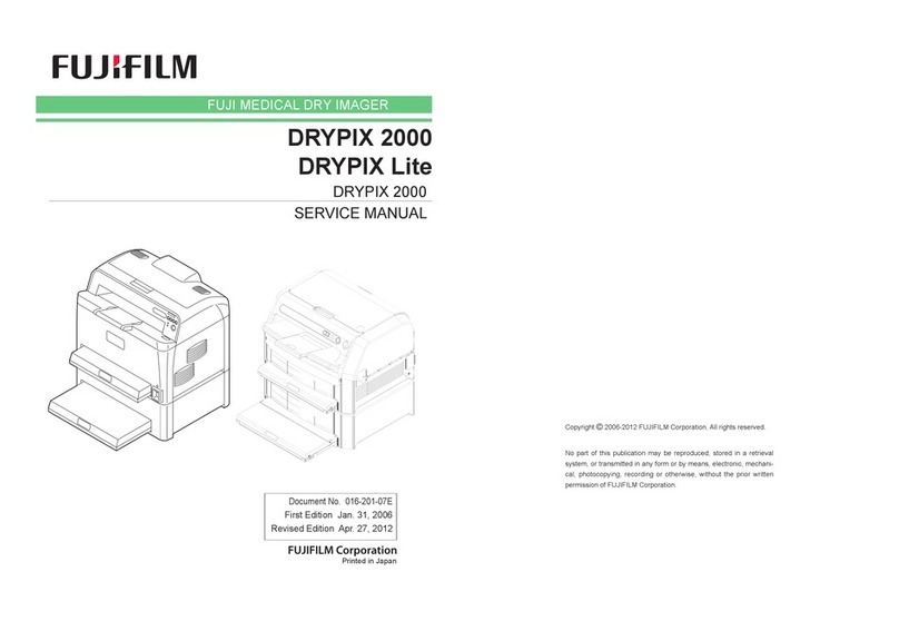
FujiFilm CR-IR346RU User manual

CR-IR346RU Service Manual
Installation (IN) (Philips Medical Systems 01.1)

CR-IR346RU
Service Manual
0.1
010-051-01
08.30.2001 FM3058 (1)
0.1
Installation (IN)
1. Specifications of Machine ........................................................................................... IN-2
2. Installation Work Flowchart ......................................................................................... IN-4
3. Preparation for Installation ......................................................................................... IN-6
3.1 Precautions Regarding Installation.................................................................. IN-6
3.2 Unloading ........................................................................................................... IN-7
3.3 Transfer............................................................................................................... IN-11
3.4 Temporary Placement ....................................................................................... IN-12
3.5 Checking the Items Supplied ............................................................................ IN-13
4. Installation Procedures ............................................................................................... IN-15
4.1 Removing the Machine-Wrapping Packing Materials..................................... IN-15
4.2 Removing the Light Protect Plates .................................................................. IN-16
4.3 Repositioning the Retaining Members ............................................................ IN-17
5. Installing the Options .................................................................................................. IN-18
5.1 Assembling the Table ........................................................................................ IN-18
6. Setting the CPU12A Board .......................................................................................... IN-22
7. Connecting the Cables ................................................................................................ IN-24
7.1 Connecting the Power Cable and Checking Resistance Value ..................... IN-24
7.2 Connecting the Interface Cable ........................................................................ IN-25
7.2.1 Direct Connection of the CL/RU .............................................................. IN-26
7.2.2 Network Connection ................................................................................. IN-27
8. Installing the Cover ...................................................................................................... IN-28
9. CL Installation Procedures .......................................................................................... IN-28
10. Final Placement ............................................................................................................ IN-29
10.1 Securing the Machine with the Adjustable Feet ............................................. IN-29
10.2 Securing the Machine with the Retainers ........................................................ IN-30
10.3 Securing the Table and Machine Together...................................................... IN-32
10.4 Securing the Machine with the Retainers and Table ...................................... IN-33
11. Powering ON the CL/RU .............................................................................................. IN-36
12. Image/Conveyance Checks ......................................................................................... IN-37
12.1 Conveyance Checks .......................................................................................... IN-38
12.2 Image Checks ..................................................................................................... IN-38
13. Powering OFF the CL/RU............................................................................................. IN-39
14. Cleaning the CL/RU ...................................................................................................... IN-39
15. Attaching the Cassette Handling Precaution Label .................................................. IN-40
CR-IR346RU Service Manual – Contents

Installation (IN) Control Sheet
CR-IR346RU
Service Manual
IN - 1
010-051-01
08.30.2001 FM3058
IN - 1
Control Sheet
Revision number Reason Pages affectedIssue date
10/10/2000 00 New release (FM2887) All pages
08/30/2001 01 Support for software version A05 (FM3058) IN-5, 6, 12–14, 17–19, 21.1–21.2,
23, 24–29, 31–35, 38

CR-IR346RU
Service Manual
IN - 2
010-051-00
10.10.2000 FM2887 (1)
IN - 2
1. Specifications of Machine
■Product Code
CR-IR346RU
■Dimensions
W550 x D515 x H1065 (mm)
FR6H7645.EPS
515
1065
Unit: mm
550
■Weight
155 kg approx.
■Means for Moving and Fixing the Machine
• Moving : Double-wheel caster (variable-direction/no-brake) x4
• Fixing : • Adjustable foot x4
• Machine retainer x2
• Table x1 (optional)
• Table x1 and table retainer x2 (optional)
010-051-00
10.10.2000 FM2887 (2)

CR-IR346RU
Service Manual
IN - 3
010-051-00
10.10.2000 FM2887 (1)
IN - 3
■Installation Space
REFERENCE
The machine may be installed with its left/right sides and its rear adjacent to the wall.
Note, however, that adequate space around the machine should be required so that the
distance from its front to the wall is 1,000 mm or greater and there is enough room to allow the
machine to rotate.
800
1,000
●Space required for servicing ●Space required for rotation
800800
FR6H7004.EPS
1,000
●Minimum space for installation
✻
:
Make sure that servicing space is secured.
●Minimum space for table (full option)
installation
1,000
✻
:
Make sure that servicing space is secured.
Unit: mm
800
800
Table Table
Machine
Machine
Machine Machine

CR-IR346RU
Service Manual
IN - 4
010-051-00
10.10.2000 FM2887 (1)
IN - 4
2. Installation Work Flowchart
3. Preparation for Installation
4. Installation Procedures
START
A
FR6H7001.EPS
3.2 Unloading
3.3 Transfer
3.4 Temporary Placement
3.5 Checking the Items Supplied
4.1 Removing the Machine-Wrapping Packing Materials
4.2 Removing the Light Protect Plates
5. Installing the Options
5.1 Assembling theTable
4.3 Repositioning the Retaining Members
6. Setting the CPU12A Board
7. Connecting the Cables
7.1 Connecting the Power Cable and Checking ResistanceValue
7.2 Connecting the Interface Cable
010-051-00
10.10.2000 FM2887 (2)

CR-IR346RU
Service Manual
IN - 5
010-051-00
10.10.2000 FM2887 (1)
IN - 5
A
8. Installing the Cover
9. CL Installation Procedures
CL Service Manual
"A. Installation/Chapters 3-7"
14. Cleaning the CL/RU
15. Attaching the Cassette Handling Precaution Label
FR6H7005.EPS
END
10. Final Placement
11. Powering ON the CL/RU
12. Image/Conveyance Checks
13. Powering OFF the CL/RU
12.1 Conveyance Checks
12.2 Image Checks
10.1 Securing the Machine with the Adjustable Feet
10.2 Securing the Machine with the Retainers
10.3 Securing the Table and Machine Together
10.4 Securing the Machine with the Retainers and Table
010-051-01
08.30.2001 FM3058

CR-IR346RU
Service Manual
IN - 6
010-051-00
10.10.2000 FM2887 (1)
IN - 6
3. Preparation for Installation
3.1 Precautions Regarding Installation
The place where the machine is to be installed needs to meet the criteria set forth in “Getting
Started” and “■Installation Site Requirements”.
Preinstallation procedures should be performed beforehand for necessary construction work,
electrical work, and air-conditioning system installation.
■Installation Site Requirements
Avoid the following installation sites:
• Places where the temperature changes drastically.
• Places near heat sources such as heaters.
• Places where water leakage or equipment submersion may occur.
• Places where corrosive gas may be generated.
• Dusty places.
• Places where the machine is subject to constant or excessive vibration or shock.
• Places that are exposed to direct sunlight.
■Handling Precautions for Printed Circuit Boards and Optical Unit
When servicing a board or optical unit, use a wristband to ground your body. If you body is
not grounded, the electrostatic buildup on your body may damage the electronic parts.
010-051-01
08.30.2001 FM3058

CR-IR346RU
Service Manual
IN - 7
010-051-00
10.10.2000 FM2887 (1)
IN - 7
FR6H7E01.EPS
#3
[Remove] Top machine-wrapping protective material
#1
[Remove]
PP band
(x4)
Carrier pallet
Machine-wrapping
protective material
#4
[Remove] Tray
#5 [Remove]
Machine-wrapping protective material
DO NOT ROLL UNSTABLE
VORSICHT
#2
[Remove] Slope
3.2 Unloading
CAUTION
When unloading or transferring the machine, use care not to incline the machine.
Because the machine is not fixed to the carrier pallet, the machine may topple down.
◆
NOTE
◆
Before unloading the machine, secure a proper machine transfer route.
(1) Move down the machine together with the carrier pallet from the load-carrying platform
of the truck.
(2) Remove the machine-wrapping protective material (reinforced corrugated board).
010-051-00
10.10.2000 FM2887 (2)

CR-IR346RU
Service Manual
IN - 8
010-051-00
10.10.2000 FM2887 (1)
IN - 8
◆
INSTRUCTION
◆
During the winter season, allow the machine to stand under its packaged condition for
sufficient time before unpacking it.
If the machine is unpacked immediately after it is carried into the room, moisture
condensation may occur on the machine.
(3) Remove the vinyl cover.
FR6H7652.EPS
Carrier pallet
[Remove] Vinyl cover
Machine

CR-IR346RU
Service Manual
IN - 9
010-051-00
10.10.2000 FM2887 (1)
IN - 9
CAUTION
To remove the four nuts that secure the machine retaining base and carrier pallet,
loosen the four nuts evenly one by one, and then remove them.
(4) Lower the machine onto the carrier pallet.
As the four nuts are loosened, the machine retaining base is lowered, so that the
machine rests down on the carrier pallet.
Machine
Carrier pallet
Machine retaining base
Nut
FR6H7602.EPS
#2
[Remove] Machine retaining corrugated board
#1
[Remove] Displacement prevention member
FRONT
Carrier pallet
Machine retaining
base
#3
[Remove] Na10 (x4)
(5) Attach the displacement prevention member.
Slope
Fitting
Slope
#2
[Shift] Fitting
Displacement
prevention
member
FR6H7619.EPS
#1
[Remove] Na6
#3
[Secure] Na6
Na6 removed at #1 should be used at #3.

CR-IR346RU
Service Manual
IN - 10
010-051-00
10.10.2000 FM2887 (1)
IN - 10
(6) Slide the position of the fitting of the slope.
REFERENCE
The slope may be attached only to the front side of the machine.
FR6H7606.EPS
[Attach] Slope
FRONT

CR-IR346RU
Service Manual
IN - 11
010-051-00
10.10.2000 FM2887 (1)
IN - 11
WARNING
When unloading the machine from the carrier pallet, two persons should cooperate to
do so using care to prevent it from toppling down.
In this case, the two persons should be positioned, one at the right-hand side and the
other at the left-hand side of the machine.
◆
NOTE
◆
The adjustable feet should be raised all the way up to their upper limit.
(7) Lower the machine from the carrier pallet.
Carrier pallet
Slope
FR6H7605.EPS
FRONT
3.3 Transfer
CAUTIONS
•When transferring the machine by use of its casters, raise the adjustable feet of the
machine all the way up to their upper limit.
•When bringing the machine into the installation place, support it so that it will not
topple down.
•When the machine should be moved over some step or bump, move it as slowly as
possible to avoid shock to it. Note that the step over which the machine may move is
about 10 mm high at most.
(1) Transfer the machine into the installation place.
010-051-00
10.10.2000 FM2887 (2)

CR-IR346RU
Service Manual
IN - 12
010-051-00
10.10.2000 FM2887 (1)
IN - 12
FR6H7013.EPS
Adjustable foot
Machine
[Secure] Na12 (x4)
Caster
3.4 Temporary Placement
(1) Secure space required for installation procedures and temporarily place the machine.
FR6H7006.EPS
Space required for installation
Rear
800
Front
1,000
Unit : mm
Space required for rotation
800800
800
800
Machine
REFERENCE
When there is enough space (800 mm around the machine) to allow the machine to
rotate, installation procedures may be performed only if 1,000 mm or greater in space
is secured on one side of the machine.
(2) Secure the machine with the adjustable feet in place.
010-051-01
08.30.2001 FM3058

CR-IR346RU
Service Manual
IN - 13
010-051-00
10.10.2000 FM2887 (1)
IN - 13
3.5 Checking the Items Supplied
Check whether all the items are supplied in accordance with the PACKING LIST that is
contained in each carton.
◆
NOTE
◆
The Test Result Sheet contained should be kept by the service person.
■Machine Main Body
TR6H7002.EPS
Check Item Qty. Remarks
Machine main body
1
Instruction Manual
1
TR6H7003.EPS
Check Item Qty. Remarks
Label One set (RU exposure marker
caution label)
1
1
Fuse set Spare
1
Test Result Sheet
1
Machine-specific data floppy
diskette 3.5-inch/1.44 MB
1
CD-ROM (for RU) For backup
(Installed prior to shipment)
1
Warranty Sheet
1
One set (Inch/metric label)
[Specifications for use in Japan]
Ferrite bead E04SR301334
1
CL/RU connection cable Used only for direct connection
without hub
Category 5 cable (cross, UTP type), 1.95 m
1
RU power cable
100-120V1
■Accessories
Instruction Manual
1
TR6H7010.EPS
Check Item Qty. Remarks
Label One set (RU exposure marker
caution label)
1
1
Fuse set Spare
1
1
Test Result Sheet
1
Machine-specific data floppy
diskette 3.5-inch/1.44 MB
1
CD-ROM (for RU) For backup
(Installed prior to shipment)
1
One set (Inch/metric label)
[Specifications for use outside Japan]
Ferrite bead E04SR301334
CL/RU connection cable Used only for direct connection
without hub
Category 5 cable (cross, UTP type), 1.95 m
1
010-051-01
08.30.2001 FM3058

CR-IR346RU
Service Manual
IN - 14
010-051-00
10.10.2000 FM2887 (1)
IN - 14
[Specification for use in Japan]
TR6H7004.EPS
Retainer For retaining the machine
1
Check Item Qty. Remarks
■Optional Items
TR6H7011.EPS
For retaining the machineRetainer
1
RU power cable
•100-120 V: U.S., Canada, etc.
•200-230 V: Germany, France,
Spain, Sweden, etc.
•240 V: U.K.
1
[Specifications for use outside Japan]
Check Item Qty. Remarks
010-051-01
08.30.2001 FM3058

CR-IR346RU
Service Manual
IN - 15
010-051-00
10.10.2000 FM2887 (1)
IN - 15
4. Installation Procedures
4.1 Removing the Machine-Wrapping Packing Materials
(1) Remove the packing materials.
#3
[Remove] Tape
FR6H7607.EPS
#2
[Remove] Retaining member
#1
[Remove] Tape
#6
[Remove] Tape
#5
[Remove] Tape
#4
[Remove] Tape (x2)/front cover

CR-IR346RU
Service Manual
IN - 16
010-051-00
10.10.2000 FM2887 (1)
IN - 16
4.2 Removing the Light Protect Plates
(1) Remove the light protect plates.
Upper light
protect plate
[Remove] T4x6 (x6)
FR6H7657.EPS
010-051-00
10.10.2000 FM2887 (2)

CR-IR346RU
Service Manual
IN - 17
010-051-00
10.10.2000 FM2887 (1)
IN - 17
4.3 Repositioning the Retaining Members
REFERENCE
The retaining members may be removed along the rope.
(1) Reposition the retaining members.
FR6H7609.EPS
[Reposition] Retaining member
[Reposition]
Retaining member
#1
[Remove/Secure]
BR4x10 (x3)
#2
[Remove] BR4x10
#3
[Loosen] BR4x10 #5
[Secure]
BR4x10 (x2)
#4
[Reposition] Retaining member
Retaining member
REFERENCE
One screw for each of the right and left retaining members removed at step #2 should
be used at step #5.
(2) Attach the upper light protect plate.
“4.2 Removing the Light Protect Plates”
010-051-01
08.30.2001 FM3058

CR-IR346RU
Service Manual (PMS_01.1)
IN - 18
010-051-00
10.10.2000 FM2887 (1)
IN - 18
5. Installing the Options
5.1 Assembling the Table
■Composition of Optional Parts
REFERENCES
• Those shown in illustration Nos.12 and 15 are used for installation with the table.
"10.3 Securing the Table and Machine Together"
• Those shown in illustration Nos.12-17 are used for table installation.
"10.4 Securing the Machine with the Retainers and Table"
●Parts used to assemble the table
FR6H7701.EPS
2. Pillar (right)
3. Rear pipe 4.Top plate
5. Shelf 6. Bracket
7.T6x35 (x8) 8.T6x12 (x4) 9.T4x6 (x4)
1. Pillar (left)
010-051-01
08.30.2001 FM3058
Table of contents
Other FujiFilm Laboratory Equipment manuals
Popular Laboratory Equipment manuals by other brands

Owen Mumford
Owen Mumford AutoSqueeze OP6100 instructions

EKO
EKO ASI-16 instruction manual

Thermoline Scientific Equipment
Thermoline Scientific Equipment TGO-80W operating instructions

IKA
IKA lab dancer 3365000 operating instructions

Particulate Systems
Particulate Systems NanoPlus Operator's manual

Civco
Civco GUS G32-S Operator's manual