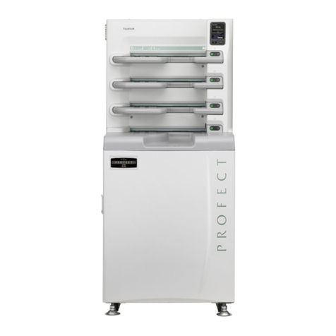
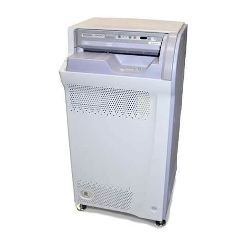
FujiFilm DRYPIX 2000 User manual

Printed in Japan
DRYPIX 2000
DRYPIX Lite
SERVICE MANUAL
Document No. 016-201-07E
First Edition Jan. 31, 2006
Revised Edition Apr. 27, 2012
No part of this publication may be reproduced, stored in a retrieval
system, or transmitted in any form or by means, electronic, mechani-
cal, photocopying, recording or otherwise, without the prior written
permission of FUJIFILM Corporation.
Copyright ©2006-2012 FUJIFILM Corporation. All rights reserved.
FUJI MEDICAL DRY IMAGER
DRYPIX 2000

DRYPIX 2000 / DRYPIX Lite
Service Manual
0.1
0.1
016-201-06E
01.27.2012 FM5920
1. HANDLING THIS SERVICE MANUAL
1.1 About This Service Manual
nScope
This Service Manual applies to the Fuji Medical Dry Imager DRYPIX 2000.
Note, however, that "Model: DRYPIX 2000" is available in two versions: DRYPIX
2000 and DRYPIX Lite, and therefore, some of the descriptions in this manual contain
version-specic information.
nNotation of Unit Symbols
For notation of unit symbols, metric units set forth in the International Systems of Units
(SI) are used, as a rule. However, some metric units that are not allowed in the SI but
are permitted under the Measurement Law are partially used.
1.2 Service Manual Appropriations
1. All rights are reserved by the FUJIFILM Corporation (FUJIFILM).
2. Manual usage is restricted to FUJIFILM equipment related technical and service
personnel.
3. This manual contains information relating to FUJIFILM equipment and is therefore
proprietary. Unauthorized disclosure is prohibited.
4. FUJIFILM's prior consent is required in regard to the following.
• Manual copying in whole or in part.
• Disclosure of manual contents to unauthorized personnel.
• Manual uses for purposes other than technical service.
5. The contents of this manual are subject to changes for product improvement.
6. Accompanying documents were originally drafted in the English language.
1.3 About Notation in the Manual
nNotation of Cautions, Warning, etc.
The notation formats of "WARNING", "CAUTION", "INSTRUCTIONS", "NOTE",
"REMARKS" and "REFERENCE" are shown below.
WARNING
Indicated where failure to observe the instruction given may result in death or
serious injuries.
CAUTION
Indicated where failure to observe the instruction given may result in light or
moderate injuries, or serious malfunction (unrecoverable or difcult to recover)
of the equipment.
<INSTRUCTIONS>
Indicated where failure to observe the instruction given may result in damage to
the equipment, or other problems.
<NOTE>
Indicated where special attention is required during a work procedure.
<REMARKS>
Indicated where description of the term used or supplementary explanation is given.
nIndication of Refer To
The " " mark is used to indicate the chapter or section you should refer to.
Its format is as indicated below.
{MC:1.1_Cover}

DRYPIX 2000 / DRYPIX Lite
Service Manual
0.2
0.2
016-201-06E
01.27.2012 FM5920
n Indication of Operation Panel Key (For DRYPIX 2000 only)
Each key on the operation panel is indicated in this Service Manual as follows.
• Counter display key: <UP> key, or
• Counter reset key: <DOWN> key, or
• Automatic density measurement key: <ENTER> key, or
• Ofine key: <CANCEL> key, or
1.4 Servicing Instruments and Tools That
Require Inspection/Calibration
The machine should be installed and serviced by use of servicing instruments and
tools that have been regularly inspected and calibrated as appropriate.
If the machine were serviced using servicing instruments and tools that have not
been inspected and calibrated, proper performance of the machine could not be
guaranteed.
Servicing instruments and tools that require inspection/calibration are as listed below.
The inspection/calibration should be planned and performed in accordance with the
specications and instruction manuals of the applicable servicing instruments and
tools.
nInstruments and Tools That Require Inspection/Calibration
Name Inspection Calibration
Digital multimeter
Densitometer
Steel ruler (300 mm)

DRYPIX 2000 / DRYPIX Lite
Service Manual
0.3
0.3
GENERAL CONTENTS SAFETY PRECAUTION
016-201-06E
01.27.2012 FM5920
SAFETY PRECAUTION
(DRYPIX 2000)
1. SAFETY PRECAUTION ............................................. 1
1.1 General Precautions........................................................................1
2. LABELS .................................................................... 3
2.1 Caution Labels ................................................................................3
2.2 Other Labels....................................................................................4
2.3 Additional Protective Grounding Earth Mark ...................................6
3. CONNECTABLE PERIPHERALS................................ 7
4. CLASSIFICATION ..................................................... 7

DRYPIX 2000 / DRYPIX Lite
Service Manual
0.4
0.4
GENERAL CONTENTS SAFETY PRECAUTION
016-201-07E
04.27.2012 FM6040
SAFETY PRECAUTION
(DRYPIX Lite)
1. SAFETY PRECAUTION ............................................. 1
1.1 General Precautions........................................................................1
2. LABELS .................................................................... 3
2.1 Caution Labels ................................................................................3
2.2 Other Labels....................................................................................4
2.3 Additional Protective Grounding Earth Mark ...................................5
3. CONNECTABLE PERIPHERALS................................ 6
4. CLASSIFICATION ..................................................... 6
5. CAUTION ON ELECTROMAGNETIC WAVES............. 7
5.1 Electromagnetic Compatibility (EMC)..............................................7
5.2 Further Information for IEC60601-1-2 .............................................7
6. CAUTIONS ON NETWORK...................................... 10

0.5
0.5
GENERAL CONTENTS SPECIFICATIONS
DRYPIX 2000 / DRYPIX Lite
Service Manual
016-201-06E
01.27.2012 FM5920
SPECIFICATIONS
1. SPECIFICATIONS ..................................................... 1
1.1 Part Name .......................................................................................1
1.1.1 DRYPIX 2000..............................................................................................1
1.1.2 DRYPIX Lite................................................................................................1
1.2 List of Optional Parts .......................................................................2
1.2.1 DRYPIX 2000..............................................................................................2
1.2.2 DRYPIX Lite................................................................................................2
1.3 GeneralSpecications ....................................................................3
1.4 Equipment Dimensions and Weight ................................................6
1.4.1 DRYPIX 2000..............................................................................................6
1.4.2 DRYPIX Lite................................................................................................7
1.5 Environmental Requirements ..........................................................8
1.6 Electrical Requirements ..................................................................9
1.7 Equipment Installation Space........................................................10
1.7.1 DRYPIX 2000............................................................................................10
1.7.2 DRYPIX Lite .............................................................................................. 11
1.8 Disposing the Equipment ..............................................................11

0.6
0.6
GENERAL CONTENTS DESCRIPTION OF EQUIPMENT (MD)
DRYPIX 2000 / DRYPIX Lite
Service Manual
016-201-06E
01.27.2012 FM5920
DESCRIPTION OF EQUIPMENT
(MD) (DRYPIX 2000)
1. OUTLINE OF EQUIPMENT.................................. MD-1
1.1 Functions of Equipment............................................................MD-1
1.2 System Conguration ...............................................................MD-2
1.3 Overall Conguration and Names of Parts...............................MD-4
1.3.1 External View .......................................................................................MD-4
1.3.2 Operation Panel ...................................................................................MD-5
1.3.3 Layout of External Interface Connectors..............................................MD-7
1.3.4 Layout of Units .....................................................................................MD-8
1.3.5 Layout of I/O Parts and Description of Functions................................. MD-9
1.3.6 Board Layout......................................................................................MD-14
1.3.7 Film Path and Jam Detection Sensor.................................................MD-15
2. STARTING UP AND ENDING THE EQUIPMENTMD-16
2.1 Powering ON ..........................................................................MD-16
2.2 Flow of Equipment Startup .....................................................MD-16
2.3 Display Transition during Equipment Startup .........................MD-17
2.4 Handling of Equipment Errors ................................................MD-18
2.4.1 Level 1 Error.......................................................................................MD-18
2.4.2 Level 0 Error.......................................................................................MD-18
2.5 Powering OFF ........................................................................MD-19
2.5.1 Ending Process..................................................................................MD-19
3. DESCRIPTION OF MECHANISM OPERATIONS MD-20
3.1 Magazine Set Section ............................................................MD-20
3.1.1 Outline................................................................................................MD-20
3.1.2 Magazine Detection/Magazine Number Identication........................ MD-20
3.1.3 Magazine Management......................................................................MD-21
3.1.4 Detection of Film Type .......................................................................MD-21
3.1.5 Protection of Removal Mechanism ....................................................MD-21
3.2 Removal Section ....................................................................MD-22
3.2.1 Outline................................................................................................MD-22
3.2.2 Magazine Shutter Open/Close Mechanism........................................MD-23
3.2.3 Operation Flow...................................................................................MD-23
3.3 Conveyor Section ...................................................................MD-28
3.3.1 Outline................................................................................................MD-28
3.3.2 Film Positioning Section.....................................................................MD-28
3.3.3 Operation Flow...................................................................................MD-29
3.4 Sub-Scanning Section............................................................MD-31
3.4.1 Outline................................................................................................MD-31
3.4.2 Film Edge Sensor...............................................................................MD-32
3.4.3 Cleaning Roller Detection ..................................................................MD-32
3.4.4 Operation Flow...................................................................................MD-33
3.5 Head.......................................................................................MD-34
3.5.1 Outline................................................................................................MD-34
3.5.2 Head Up/Down Section......................................................................MD-34
3.5.3 Thermal Head ....................................................................................MD-35
3.5.4 Operation Flow...................................................................................MD-36
3.5.5 Precautions on Opening/Closing the Head Assembly..................... MD-37.1
3.6 Film Release Section .............................................................MD-38

0.7
0.7
GENERAL CONTENTS DESCRIPTION OF EQUIPMENT (MD)
DRYPIX 2000 / DRYPIX Lite
Service Manual
016-201-06E
01.27.2012 FM5920
3.6.1 Outline................................................................................................MD-38
3.6.2 Density Measurement ........................................................................MD-38
3.6.3 Operation Flow...................................................................................MD-38
4. DESCRIPTION OF ELECTRICAL CONTROL...... MD-39
4.1 System Block Diagram ...........................................................MD-39
4.2 Outline of Power Supply.........................................................MD-40
4.3 Interlock Control .....................................................................MD-42
4.4 Functions of Boards ...............................................................MD-44
4.4.1 CPU Board.........................................................................................MD-44
4.4.2 SND Board.........................................................................................MD-45
4.4.3 THC Board .........................................................................................MD-46
4.4.4 PNL Board..........................................................................................MD-48
4.4.5 Power Supply Unit..............................................................................MD-49
5. IMAGE PROCESSING ....................................... MD-50
5.1 Image Input ............................................................................MD-50
5.1.1 Valid Services.....................................................................................MD-50
5.1.2 Service Availability .............................................................................MD-50
5.1.3 Image Data Reception Availability......................................................MD-50
5.1.4 DICOM Settings and Restrictions ......................................................MD-50
5.2 Image Spool Management Function ......................................MD-51
5.3 Image Processing...................................................................MD-53
5.3.1 Image Processing 1 ...........................................................................MD-53
5.3.2 Image Processing 2 ...........................................................................MD-54
5.3.3 Image Processing 3 ...........................................................................MD-54
5.3.4 Annotation..........................................................................................MD-55
5.3.5 Recording Pixel Size..........................................................................MD-56
6. PRINTING FORMATS........................................ MD-57
6.1 Reading the Format Name .....................................................MD-57
6.2 Standard Formats...................................................................MD-57
6.3 Mixed Formats........................................................................MD-58

0.8
0.8
GENERAL CONTENTS DESCRIPTION OF EQUIPMENT (MD)
DRYPIX 2000 / DRYPIX Lite
Service Manual
016-201-06E
01.27.2012 FM5920
DESCRIPTION OF EQUIPMENT
(MD) (DRYPIX Lite)
1. OUTLINE OF EQUIPMENT.................................. MD-1
1.1 Functions of Equipment............................................................MD-1
1.2 System Conguration ...............................................................MD-1
1.3 Overall Conguration and Names of Parts...............................MD-2
1.3.1 External View .......................................................................................MD-2
1.3.2 Operation Panel ...................................................................................MD-3
1.3.3 Layout of External Interface Connectors..............................................MD-4
1.3.4 Layout of Units .....................................................................................MD-5
1.3.5 Layout of I/O Parts and Description of Functions................................. MD-6
1.3.6 Board Layout...................................................................................... MD-11
2. STARTING UP AND ENDING THE EQUIPMENTMD-12
2.1 Powering ON ..........................................................................MD-12
2.2 Handling of Equipment Errors ................................................MD-12
2.2.1 Level 1 Error.......................................................................................MD-12
2.2.2 Level 0 Error.......................................................................................MD-13
2.3 Powering OFF ........................................................................MD-14
2.3.1 Ending Process..................................................................................MD-14
3. DESCRIPTION OF ELECTRICAL CONTROL...... MD-15
3.1 System Block Diagram ...........................................................MD-15
3.2 Interlock Control .....................................................................MD-16
3.3 Functions of Boards ...............................................................MD-16
3.3.1 CPU Board.........................................................................................MD-16
3.3.2 SND Board.........................................................................................MD-17
3.3.3 RLY Board..........................................................................................MD-18
3.3.4 Power Supply Unit..............................................................................MD-19
4. IMAGE PROCESSING ....................................... MD-20
5. PRINTING FORMATS........................................ MD-21

0.9
0.9
GENERAL CONTENTS TROUBLESHOOTING (MT)
DRYPIX 2000 / DRYPIX Lite
Service Manual
016-201-06E
01.27.2012 FM5920
TROUBLESHOOTING (MT)
(DRYPIX 2000)
1. TROUBLESHOOTING METHOD .......................... MT-1
2. ERROR CODE ..................................................... MT-2
2.1 Checking Error Codes ............................................................. MT-2
2.2 Format of Detailed Information................................................. MT-4
2.2.1 FLH Related (Conveyance) Errors Detailed Information.......................MT-4
2.2.2 MFC Related (Data Setting/System Related) Error Detailed Information .....
MT-7
2.2.3 HED Related (Head Control Related) Error Detailed Information........MT-8
2.3 Error Code Table ...................................................................... MT-9
2.3.1 Printer..................................................................................................MT-10
2.3.2 Formatter.............................................................................................MT-39
3. ABNORMAL OPERATIONS ............................... MT-58
3.1 Initialization Error at Startup ................................................... MT-58

0.10
0.10
GENERAL CONTENTS TROUBLESHOOTING (MT)
DRYPIX 2000 / DRYPIX Lite
Service Manual
016-201-06E
01.27.2012 FM5920
TROUBLESHOOTING (MT)
(DRYPIX Lite)
1. TROUBLESHOOTING METHOD .......................... MT-1
2. ERROR CODE ..................................................... MT-2
2.1 Checking Error Codes ............................................................. MT-2
2.2 Format of Detailed Information................................................. MT-2
2.2.1 FLH Related (Conveyance) Errors Detailed Information.......................MT-3
2.2.2 MFC Related (Data Setting/System Related) Error Detailed Information .....
MT-5
2.2.3 HED Related (Head Control Related) Error Detailed Information........MT-5
2.3 Error Code Table ...................................................................... MT-6
2.3.1 Printer....................................................................................................MT-7
2.3.2 Formatter.............................................................................................MT-34
3. Initializing IP Address ..................................... MT-53

0.11
0.11
GENERAL CONTENTS REMOVAL AND ADJUSTMENT (MC)
DRYPIX 2000 / DRYPIX Lite
Service Manual
016-201-06E
01.27.2012 FM5920
REMOVAL AND ADJUSTMENT
(MC) (DRYPIX 2000)
PRECAUTIONS ON INSPECTIONS, REPLACEMENTS,
AND ADJUSTMENTS.......................................... MC-1
CONTENTS ............................................................... MC-2
1. COVER................................................................ MC-4
1.1 Covers which can be Removed Individually.............................MC-4
1.1.1 Upper Cover.........................................................................................MC-4
1.2 Covers which Need to be Removed in Certain Order ..............MC-5
1.2.1 Head Up/Down Secion Cover ..............................................................MC-5
1.2.2 Ejection Cover......................................................................................MC-6
1.2.3
Front Cover ................................................................................................MC-6
1.2.4 Right Cover/Left Cover.........................................................................MC-7
1.2.5 Upper Rear Cover................................................................................MC-7
1.2.6 Rear Cover...........................................................................................MC-8
1.2.7 Rear Open/Close Cover.......................................................................MC-8
1.2.8 Lower Front Cover (Sheet-Feeder Unit)...............................................MC-9
1.2.9 Lower Right Cover/Lower Left Cover (Sheet-Feeder Unit) ................MC-10
1.2.10 Lower Rear Cover (Sheet-Feeder Unit) ............................................. MC-11
1.2.11 Lower Rear Open/Close Cover (Sheet-Feeder Unit) .........................MC-12
2. FRAME.............................................................. MC-13
2.1 Head Cover Interlock Switch (SK12)......................................MC-13
2.2 Rear Cover Interlock Switches (Upper) (SK11)......................MC-14
3. MAGAZINE SET SECTION ................................ MC-15
3.1
Film Size Detection Sensor Assembly (SA11/SA12/SA13) ....................MC-15
3.2 Magazine Shutter Open/Close Mechanism............................MC-16
4. REMOVAL SECTION ......................................... MC-17
4.1 Film Removing Motor (MB11).................................................MC-17
4.2 Suction Cup Arm ....................................................................MC-18
4.3 Suction Cup............................................................................MC-20
4.4 Bellows ...................................................................................MC-21
4.5 Removal Drive Cam ...............................................................MC-23
4.6 Removal Conveyance Roller (Lower).....................................MC-26
4.7 Suction Cup Arm HP Detection Sensor (SB11)......................MC-27
4.8 Film Surface Detection Sensor (SB12) ..................................MC-28
4.9 Suction Cup Arm Upper Deadpoint Detection Sensor (SB13) ...... MC-29
5. CONVEYOR SECTION....................................... MC-30
5.1 Positioning Guide Assembly...................................................MC-30
5.2 Reference Plate Drive Motor (MD12) .....................................MC-32
5.3 Reference Plate Assembly .....................................................MC-33
5.4 Film Edge Sensor Assembly ..................................................MC-34
5.5 Cleaning Roller Detection Sensor (SD14)..............................MC-36
6. SUB-SCANNING SECTION ............................... MC-37
6.1 Sub-scanning Motor (ME1) ....................................................MC-37
6.1.1 Removal/Reinstallation ......................................................................MC-37
6.1.2 Adjustments in Replacement of Sub-scanning Motor (ME1) ............. MC-39
6.2 Flywheel .................................................................................MC-40
6.3 Platen Roller...........................................................................MC-42

0.12
0.12
GENERAL CONTENTS REMOVAL AND ADJUSTMENT (MC)
DRYPIX 2000 / DRYPIX Lite
Service Manual
016-201-06E
01.27.2012 FM5920
7. HEAD UP/DOWN SECTION ............................... MC-44
7.1
Head Cooling Fan (FANP1, FANP2) ............................................ MC-44
7.2 Head UP/Down Drive Motor (MH1) .......................................... MC-46
7.3
Head Pressurization Arm Assembly ....................................................MC-47
7.4 Check/Adjustment of Thermal Head Pressure ....................MC-47.1
8. HEAD ................................................................ MC-48
8.1 Thermal Head Assembly ........................................................MC-48
8.1.1 Removal/Reinstallation ......................................................................MC-48
8.1.2 Adjustments in Replacement of Thermal Head..................................MC-50
9. FILM RELEASE SECTION ................................. MC-54
9.1 Density Measurement Light-Sensing Board (PDD15A) .........MC-54
9.2 Density Measurement Light-Emitting Board (LED15A) ..........MC-56
10. CONTROLLER................................................... MC-58
10.1 Operation Panel .....................................................................MC-58
10.2 Controller Cooling Fan (FANK1).............................................MC-59
10.3 CPU Board .............................................................................MC-60
10.4 SND Board .............................................................................MC-61
10.4.1 Removal/Reinstallation ...................................................................... MC-61
10.4.2 Precautions on Replacement of SND Board................................... MC-61.1
10.5 Power Supply Unit..................................................................MC-62
10.5.1 Removal/Reinstallation ...................................................................... MC-62
10.5.2 Adjustments in Replacement of Power Supply Unit........................... MC-64
10.6 ME1 Driver Board...................................................................MC-67
10.7 Lithium Battery .......................................................................MC-68
10.8 CF (Compact Flash Memory) .................................................MC-69
10.8.1 Removal/Reinstallation ...................................................................... MC-69
10.8.2 Recovery of CF .................................................................................. MC-69
10.9 Control Box.............................................................................MC-70
10.10 Head Voltage Switching Relay Assembly...............................MC-73
11. SHEET-FEEDER UNIT ....................................... MC-75
11.1 Sheet-feeder Unit Film Removing Motor (MB21) ...................MC-77
11.2 Sheet-feeder Unit Positioning Guide Assembly......................MC-78
12. INSTALLING THE MAIN UNIT SOFTWARE ...... MC-80
12.1 Installing from the PC for Servicing ........................................MC-81
12.1.1 Copying Main Unit Software to the PC for Servicing.......................... MC-81
12.1.2 Upgrading the Version from the PC for Servicing .............................. MC-82
12.1.3 Full Installation from the PC for Servicing.......................................... MC-83
12.2 Installing from the USB Memory.............................................MC-85
12.2.1 Copying Main Unit Software to the USB Memory .............................. MC-85
12.2.2 Upgrading the Version from the USB Memory................................... MC-87
12.2.3 Full Installation from the USB Memory............................................... MC-88
13. RECOVERY PROCEDURE FOR CF (COMPACT FLASH
MEMORY) ......................................................... MC-90
13.1 When not Using the Main Unit Software CD-R at the Installed
Place ......................................................................................MC-90
13.1.1 Copying the Main Unit Software to the PC for Servicing.................... MC-90
13.1.2 Transferring the Main Unit Software to CF.........................................MC-91
13.2 When Using the Main Unit Software CD-R at the Installed Place .....
...............................................................................................MC-92

0.14
0.14
GENERAL CONTENTS REMOVAL AND ADJUSTMENT (MC)
DRYPIX 2000 / DRYPIX Lite
Service Manual
016-201-06E
01.27.2012 FM5920
REMOVAL AND ADJUSTMENT
(MC) (DRYPIX Lite)
PRECAUTIONS ON INSPECTIONS, REPLACEMENTS,
AND ADJUSTMENTS.......................................... MC-1
1. COVER................................................................ MC-2
1.1 Right Cover ..............................................................................MC-2
1.2 Left Cover.................................................................................MC-2
1.3 Head Cover ..............................................................................MC-3
1.4 Upper Tray Cover .....................................................................MC-3
1.5 Lower Tray Cover .....................................................................MC-4
1.6 Front Cover ..............................................................................MC-4
1.7 Upper Rear Cover ....................................................................MC-5
1.8 Rear Cover ...............................................................................MC-5
1.9 Lower Right Cover (Sheet-Feeder Unit)...................................MC-6
1.10 Lower Left Cover (Sheet-Feeder Unit) .....................................MC-6
1.11 Lower Front Cover (Sheet-Feeder Unit)...................................MC-7
2. FRAME................................................................ MC-8
2.1 Head Cover Interlock Switch (SK12)........................................MC-8
2.2 Rear Cover Interlock Switch (SK21).........................................MC-9
3. MAGAZINE SET SECTION ................................ MC-10
3.1 Film Size Detection Sensor Assembly (SA11/SA12/SA13) ....MC-10
3.2 Magazine Shutter Open/Close Mechanism............................MC-10
4. REMOVAL SECTION ......................................... MC-12
4.1 Film Removing Motor (MB11).................................................MC-12
4.2 Suction Cup Arm ....................................................................MC-13
4.3 Suction Cup............................................................................MC-14
4.4 Bellows ...................................................................................MC-15
4.5 Removal Drive Cam ...............................................................MC-16
4.6 Removal Conveyance Roller (Lower).....................................MC-20
4.7 Film Conveyance Guide .........................................................MC-21
4.8 Conveyance Entrance Sensor (SD11) ...................................MC-22
4.9 Reference Plate HP Detection Sensor (SD13).......................MC-22
4.10 Suction Cup Arm HP Detection Sensor (SB11)......................MC-23
4.11 Film Surface Detection Sensor (SB12) ..................................MC-24
4.12 Suction Cup Arm Upper Deadpoint Detection Sensor (SB13) ...... MC-24
5. CONVEYOR SECTION....................................... MC-26
5.1 Positioning Guide Assembly...................................................MC-26
5.2 Conveyor section motor (MD11).............................................MC-28
5.3 Reference Plate Drive Motor (MD12) .....................................MC-28
5.4 Reference Plate Assembly .....................................................MC-29
5.5 Film Edge Sensor Assembly ..................................................MC-30
5.6 Conveyance exit sensor (SD12).............................................MC-31
6. SUB-SCANNING SECTION ............................... MC-32
6.1 Sub-scanning Motor (ME1) ....................................................MC-32
6.1.1 Removal/Reinstallation ......................................................................MC-32
6.1.2 Adjustments in Replacement of Sub-scanning Motor (ME1) ............. MC-34
6.2 Flywheel .................................................................................MC-35

0.15
0.15
GENERAL CONTENTS REMOVAL AND ADJUSTMENT (MC)
DRYPIX 2000 / DRYPIX Lite
Service Manual
016-201-06E
01.27.2012 FM5920
6.3 Platen Roller...........................................................................MC-37
7. HEAD UP/DOWN SECTION ............................... MC-39
7.1 Head Cooling Fan (FANP1)....................................................MC-39
7.2 Head UP/Down Drive Motor (MH1) ........................................MC-40
7.3 Check/Adjustment of Thermal Head Pressure .......................MC-42
8. HEAD ................................................................ MC-43
8.1 Thermal Head Assembly ........................................................MC-43
8.2 Adjustments in Replacement of Thermal Head......................MC-45
8.2.1 Transferring the Head Power Voltage ................................................ MC-45
8.2.2 Adjusting the Head Power Voltage.....................................................MC-45
8.2.3 Check/Adjustment of Thermal Head Pressure...................................MC-46
8.2.4 Checking the Image ...........................................................................MC-46
9. FILM RELEASE SECTION ................................. MC-47
9.1 Density Measurement Light-Sensing Board (PDD28A) .........MC-47
9.2 Density Measurement Light-Emitting Board (LED28A) ..........MC-48
10. CONTROLLER................................................... MC-50
10.1 Operation Panel .....................................................................MC-50
10.2 Control Box.............................................................................MC-50
10.3 Controller Cooling Fan (FANK1).............................................MC-52
10.4 CPU Board .............................................................................MC-53
10.5 SND Board .............................................................................MC-54
10.6 Power Supply Unit..................................................................MC-55
10.7 RLY32A Board........................................................................MC-57
10.8 CF (Compact Flash Memory) .................................................MC-57
10.8.1 Removal/Reinstallation ...................................................................... MC-57
10.8.2 Recovery of CF .................................................................................. MC-58
10.9 Power Switch and AC Inlet .....................................................MC-58
11. RECOVERY PROCEDURE FOR CF (COMPACT FLASH
MEMORY)} ........................................................ MC-60
11.1 Copying the Main Unit Software to the PC for Servicing........MC-60
11.2 Copying the Main Unit Software to the CF .............................MC-61

0.16
0.16
GENERAL CONTENTS SERVICE MODE (MU)
DRYPIX 2000 / DRYPIX Lite
Service Manual
016-201-06E
01.27.2012 FM5920
SERVICE MODE (MU)
(DRYPIX 2000)
1. OUTLINE OF SERVICE MODE ............................MU-1
1.1 Transition of Modes in DRYPIX 2000.......................................MU-1
1.2 Note on Executing Service Mode .............................................MU-1
1.3 Operations of Main Unit Service Modes...................................MU-2
1.4 Details of Message Display ......................................................MU-2
1.5 Note on Executing Service Mode .............................................MU-3
2. U-UTILITY (USER-UTILITY) ...............................MU-4
2.1 U-Utility Menu Tree...................................................................MU-4
2.2 Starting and Ending U-Utility ....................................................MU-4
2.3 Details of U-Utility Commands .................................................MU-5
[1] Set Date>......................................................................................MU-5
[1-1] Check Date ......................................................................... MU-5
[1-2] YYYY> ................................................................................ MU-5
[2] Check Version...............................................................................MU-5
[3] Film Counters>.............................................................................. MU-6
[3-1] User Counter> .................................................................... MU-6
[3-1-1] Check Counters ....................................................... MU-6
[3-1-2] Initiate> ....................................................................MU-6
[3-2] Set Rem.Films> .................................................................. MU-6
[3-2-1] Initiate> ....................................................................MU-6
[4] Film Output> .................................................................................MU-7
[4-1] 17-Steps> ........................................................................... MU-7
[4-2] SMPTE> ............................................................................. MU-7
[4-3] Cleaning Film......................................................................MU-7
[5] QC>...............................................................................................MU-8
[5-1] QC PATTERN .....................................................................MU-8
[5-2] SETTINGS>........................................................................ MU-8
[5-2-1] BUILD-IN DEN.>...................................................... MU-8
[5-2-1-1] Auto ................................................................MU-8
[5-2-1-2] Manual>.......................................................... MU-8
[6] Sleep Mode>................................................................................. MU-9
[7] Calibration.....................................................................................MU-9
2.4 Other Utilities .........................................................................MU-10
[8] Counter Display .......................................................................... MU-10
[9] Counter Reset.............................................................................MU-10
[10] Automatic Density Correction ..................................................... MU-10
3. M-UTILITY (
MAINTENANCE-UTILITY
) ...............MU-11
3.1 U-Utility Menu Tree................................................................. MU-11
3.2 Starting and Ending M-Utility..................................................MU-13
3.2.1 Starting M-Utility.................................................................................MU-13
3.2.2 Ending M-Utility..................................................................................MU-13
3.3 Details of M-Utility Commands ...............................................MU-14
[1] System>......................................................................................MU-14
[1-1] Conguration> ..................................................................MU-14
[1-1-1] Set Date>............................................................... MU-14
[1-1-1-1] Check Date................................................... MU-14
[1-1-1-2] YYYY>.......................................................... MU-14
[1-1-2] Set Magazines> ..................................................... MU-14
[1-1-3] Option Slot>........................................................... MU-15
[1-1-3-1] Enable Slot ................................................... MU-15
[1-1-4] Set QC>................................................................. MU-15
[1-1-4-1] Enable QC> ................................................. MU-15
[1-1-4-2] Set Tgt. Den.> .............................................. MU-15
[1-1-4-3] Printing Dmax>............................................. MU-16
[1-1-6] Film Counters> ...................................................... MU-16
[1-1-6-1] Check Counters............................................ MU-16
[1-1-6-2] Init.Trip-cnt> ................................................. MU-17
[1-1-6-3] Set Odo-cnt> ................................................MU-17
[1-1-6-4] Set Rem.Films>............................................ MU-17
[1-1-7] Set Network> ......................................................... MU-18
[1-1-7-1] DICOM> .......................................................MU-18
[1-1-7-1-1] AE-title> ..............................................MU-18
[1-1-7-1-2] Port No.>............................................. MU-18

0.17
0.17
GENERAL CONTENTS SERVICE MODE (MU)
DRYPIX 2000 / DRYPIX Lite
Service Manual
016-201-06E
01.27.2012 FM5920
[1-1-7-2] NETWORK>................................................. MU-19
[1-1-7-2-1] IP Address...........................................MU-19
[1-1-7-2-2] SubNetMask .......................................MU-19
[1-1-7-2-3] Hostname............................................ MU-20
[1-1-7-2-4] Gateways.>.........................................MU-20
[1-1-7-2-5] Show Mac Addr.>................................MU-20
[1-1-7-2-6] Regist PC>.......................................... MU-21
[1-1-8] Ele Save Mode> .................................................... MU-21
[1-1-8-1] Transit.Time>................................................ MU-21
[1-1-9] User 17-Steps>...................................................... MU-22
[1-1-10] User SMPTE>........................................................ MU-22
[1-2] Error Log>......................................................................... MU-22
[1-2-1] Show Err. Log ........................................................ MU-22
[1-2-2] Clear ......................................................................MU-22
[1-2-3] Save Log File>....................................................... MU-22
[1-2-4] Logging mode> ...................................................... MU-23
[1-3] Set Panel> .....................................................................MU-23.1
[1-3-1] Alarm Sound>..................................................... MU-23.1
[1-3-2] Alarm Volume> ................................................... MU-23.1
[1-3-3] Language>............................................................. MU-24
[1-3-4] Size Type> ............................................................. MU-24
[2] USB Memory............................................................................... MU-25
[2-1] Installation>....................................................................... MU-25
[2-1-1] Upgrade .................................................................MU-25
[2-1-2] Full install............................................................... MU-25
[2-2] Save/Load......................................................................... MU-26
[2-2-1] Save to USB> ........................................................ MU-26
[2-2-2] Load from USB> .................................................... MU-27
[3] Film Output> ...............................................................................MU-28
[3-3] Grid&FlatPat.> ..................................................................MU-28
[3-6] SMPTE> ........................................................................... MU-28
[3-13] CleaningFilm>................................................................... MU-28
[4] F.D.C.>........................................................................................ MU-29
[4-1] AUTO F.D.C.>...................................................................MU-29
[4-2] Check Density>.................................................................MU-29
[4-3] 24-Steps> ......................................................................... MU-30
[4-4] Manual F.D.C.>.................................................................MU-30
[4-5] Densitometer ....................................................................MU-31
[4-5-1] 24-Steps> ..............................................................MU-31
[4-5-2] Set Colle. T.> ......................................................... MU-31
[4-5-3] Clr Colle. T.> .......................................................... MU-32
[4-5-4] DM Sen. Moni. ......................................................MU-32
[4-6] Densito.Lamp>.................................................................. MU-32
[6] Print Posit.>................................................................................. MU-33
[6-1] Side Margin.......................................................................MU-33
[6-2] Enable Shift> .................................................................... MU-34
[6-3] Top Margin>......................................................................MU-34
[6-3-1] Adjust>................................................................... MU-34
[6-3-2] Initialize>............................................................. MU-34.1
[7] Check Mech.>............................................................................. MU-35
[7-1] Film Removing>................................................................MU-35
[7-2] Motor Ope.>......................................................................MU-36
[7-2-1] MD11> ................................................................... MU-36
[7-2-2] ME1> .....................................................................MU-37
[7-3] HEAD U/D>.......................................................................MU-38
[7-4] Print Posi.> .......................................................................MU-39
[7-4-1] MD12> ...................................................................MU-39
[7-4-2] MD22> ...................................................................MU-39
[7-5] Sub Scan.> .......................................................................MU-40
[7-5-1] Sub Scan.Speed.................................................... MU-40
[7-5-2] Initialize>................................................................ MU-40
[7-5-3] Adjust>................................................................... MU-40
[7-6] Edge Sen.Po.>..................................................................MU-41
[7-7] Edge Sen.Mo.>................................................................. MU-42
[7-8] Edge Sen.LED>................................................................ MU-42
[7-9] Sensor Monit.>..................................................................MU-43
[7-10] NipAdjustment> .............................................................MU-43.1
[8] Head Check> ..............................................................................MU-44
[8-1] Temperature......................................................................MU-44
[8-2] Fan Operation>.................................................................MU-44
[8-3] Head Voltage. ...................................................................MU-44
[8-4] 16VH Ope.>...................................................................... MU-44

0.18
0.18
GENERAL CONTENTS SERVICE MODE (MU)
DRYPIX 2000 / DRYPIX Lite
Service Manual
016-201-06E
01.27.2012 FM5920
4. PC-Utility..........................................................MU-45
4.1 Work Preparations of PC for Servicing...................................MU-45
4.1.1 Environment of PC for Servicing........................................................MU-45
4.1.2 Preparations for Using the PC for Servicing ......................................MU-46
4.1.3 Setting the FTP Site Directory of the PC............................................MU-46
4.1.4 Setting Grouping Symbols .................................................................MU-48
4.1.5 Creating the Data Storage Folder ...................................................... MU-50
4.1.6 Precaution and Settings in the Use of Windows XP PC for ServicingMU-51
4.2 Flow of PC-Utility Operations .................................................MU-55
4.2.1 Connecting PC for Servicing to the Network......................................MU-55
4.2.2 Connecting the PC for Servicing to the Equipment (Web Server Start).......
...........................................................................................................MU-55
4.2.3 Connecting the PC for Servicing to the Equipment (Starting PC-Utility).......
...........................................................................................................MU-55
4.2.4 PC-Utility Operations..........................................................................MU-57
4.2.5 Disconnecting the Equipment ............................................................MU-62
4.3 PC-Utility Menu Tree ..............................................................MU-63
4.4 PC-Utility Command Details...................................................MU-67
[PC1] System information and setup .................................................... MU-67
[PC1-1] Setting1............................................................................. MU-67
[PC1-1-1] Set DICOM ............................................................ MU-67
[PC1-1-1-1] AE Title .........................................................MU-67
[PC1-1-1-2] Port No. ........................................................MU-67
[PC1-1-2] Set Network ........................................................... MU-67
[PC1-1-2-1] IP Address .................................................... MU-67
[PC1-1-2-2] Sub Net Mask...............................................MU-68
[PC1-1-2-3] Gateway .......................................................MU-68
[PC1-1-2-4] Host Name ................................................... MU-68
[PC1-1-3] Display Mac address ............................................. MU-68
[PC1-1-4] Registration service pc .......................................... MU-69
[PC1-2] Setting2............................................................................. MU-69
[PC1-2-1] Set Magazines ....................................................... MU-69
[PC1-2-2] Option Slot .............................................................MU-69
[PC1-2-3] Enable QC .............................................................MU-70
[PC1-2-4] Set Target Den. ...................................................... MU-70
[PC1-2-5] Printing Dmax ........................................................ MU-70
[PC1-2-6] Set Rem. Films ...................................................... MU-70
[PC1-2-7] User 17-Steps........................................................ MU-70
[PC1-2-8] User SMPTE.......................................................... MU-71
[PC1-2-9] Display indv. data................................................... MU-71
[PC1-3] Setting3............................................................................. MU-71
[PC1-3-1] Set Date................................................................. MU-71
[PC1-3-2] Ele Save Mode ...................................................... MU-71
[PC1-3-3] Set Alarm ............................................................... MU-72
[PC1-3-4] Set Language ........................................................ MU-72
[PC1-3-5] Size Type ...............................................................MU-72
[PC1-4] Log data............................................................................ MU-73
[PC1-4-1] Display Error Log ................................................... MU-73
[PC1-4-2] Clear Error Log ...................................................... MU-73
[PC1-4-3] Display DICOM Log ............................................... MU-73
[PC1-4-4] Logging Mode ..................................................... MU-73.1
[PC2] Transfer Indv. Data...................................................................MU-73.2
[PC3] ClientConguration .................................................................... MU-74
[PC3-1] Add Client ......................................................................... MU-74
[PC3-2] Delete Client ..................................................................... MU-76
[PC3-3] Change Client Name ........................................................MU-77
[PC3-3a] Read CLTInfo................................................................. MU-77.1
[PC3-4] Clients............................................................................... MU-78
[PC3-4-1] Protocol.................................................................. MU-79
[PC3-4-1-1] Attribute list error (0107H Warning)..............MU-79
[PC3-4-1-2] N Event Report RQ ...................................... MU-79
[PC3-4-1-3] Attribute Value Out Of Range (0116H Warning)......
.....................................................................MU-80
[PC3-4-1-4] Image Size Is Larger Than imagebox (B604H
Warning) .......................................................MU-80
[PC3-4-1-5] Change Film Size .........................................MU-80
[PC3-4-1-6] Use System Timeout ....................................MU-81
[PC3-4-1-7] Presentation LUT.......................................... MU-81
[PC3-4-1-8] Precede Picking Up......................................MU-81

0.19
0.19
GENERAL CONTENTS SERVICE MODE (MU)
DRYPIX 2000 / DRYPIX Lite
Service Manual
016-201-06E
01.27.2012 FM5920
[PC3-4-1-9] Use Max/Min Density ................................... MU-81
[PC3-4-1-10] Extension Format ID..................................... MU-82
[PC3-4-1-11] Use Default Annotation................................. MU-82
[PC3-4-1-12] Change Base Color (Disable:110H[F]) ......... MU-82
[PC3-4-1-13] DeneFilmSizeof11x14............................. MU-83
[PC3-4-2] Magnify ..................................................................MU-83
[PC3-4-2-1] Default Smoothing Type ............................... MU-83
[PC3-4-2-2] Default Requested Decimate/Crop BehaviorMU-84
[PC3-4-2-3] MagnicationType........................................ MU-85
[PC3-4-2-4] Requested Image Size .................................MU-85
[PC3-4-2-5] DefaultMagnicationType ........................... MU-85
[PC3-4-2-6] Default Smoothing Type ............................... MU-85
[PC3-4-2-7] Default Requested Image Size..................... MU-86
[PC3-4-2-8] Default Decimate/Crop Behavior.................. MU-86
[PC3-4-2-9] Procedure.....................................................MU-86
[PC3-4-2-10] Edge Detection.............................................MU-86
[PC3-4-2-11] Detection Level............................................. MU-87
[PC3-4-2-12] Sharpness ....................................................MU-87
[PC3-4-2-13] Character Color ............................................MU-87
[PC3-4-3] LUT Common.........................................................MU-88
[PC3-4-3-1] Default LUT ..................................................MU-88
[PC3-4-3-2] Illumination ...................................................MU-88
[PC3-4-3-3] Ambient Light ...............................................MU-88
[PC3-4-3-4] CongurationInformation(DefaultLUT#) .... MU-88
[PC3-4-3-5] Default Illumination.......................................MU-89
[PC3-4-3-6] Default Ambient Light ................................... MU-89
[PC3-4-3-7] Procedure.....................................................MU-89
[PC3-4-4] LUT1 to LUT8 ........................................................ MU-90
[PC3-4-4-1] Max Density.................................................. MU-90
[PC3-4-4-2] Min Density................................................... MU-90
[PC3-4-4-3] γTableNo.....................................................MU-90
[PC3-4-4-4] Contrast........................................................MU-90
[PC3-4-4-5] Number of Tuning Points..............................MU-91
[PC3-4-4-6] Density .........................................................MU-91
[PC3-4-4-7] Shift ..............................................................MU-91
[PC3-4-4-8] Contrast........................................................MU-91
[PC3-4-5] Output Format........................................................ MU-92
[PC3-4-5-1] Film Size....................................................... MU-92
[PC3-4-5-2] Medium Type................................................ MU-92
[PC3-4-5-3] Film Orientation ............................................ MU-92
[PC3-4-5-4] Border Density.............................................. MU-92
[PC3-4-5-5] Polarity .........................................................MU-92
[PC3-4-5-6] Trim .............................................................. MU-93
[PC3-4-5-7] Trim Width .................................................... MU-93
[PC3-4-5-8] Trim Density ................................................. MU-93
[PC3-4-5-9] Number of Copies ........................................ MU-93
[PC3-4-5-10] Print Priority..................................................MU-93
[PC3-4-5-11] Default Number of Copies ............................MU-94
[PC3-4-5-12] Default Print Priority .....................................MU-94
[PC3-4-5-13] Default Medium Type.................................... MU-94
[PC3-4-5-14] Default Film Orientation................................ MU-94
[PC3-4-5-15] Default Film Size .......................................... MU-95
[PC3-4-5-16] Default Border Density ................................. MU-95
[PC3-4-5-17] Default Trim ..................................................MU-95
[PC3-4-5-18] Default Polarity ............................................. MU-95
[PC3-4-5-19] Mirror ............................................................MU-96
[PC3-4-5-20] Margin Between Image ................................ MU-96
[PC3-4-5-21] Image Layout................................................ MU-96
[PC3-4-5-22] Processing Type........................................... MU-97
[PC3-4-5-23] Image Crop UPDWN Area............................ MU-97
[PC3-4-5-24] Image Crop Side Area .................................. MU-97
[PC3-4-6] Annotation.............................................................. MU-98
[PC3-4-6-1] Annotation Font ............................................ MU-98
[PC3-4-6-2] Annotation Extend ........................................ MU-98
[PC3-4-6-3] Upper Left/Upper Center/Upper Right/Lower Left/
Lower Center/Lower Right............................ MU-98
[PC3-5] Common ........................................................................... MU-99
[PC3-5-1] Data Transfer Timeout ........................................... MU-99
[PC3-5-2] Association Count.................................................. MU-99
[PC3-5-3] Logging DICOM ..................................................... MU-99
[PC3-5-4] Model ...................................................................MU-100
[PC3-5-5] Manufacturer........................................................ MU-100
[PC3-5-6] Default Client .......................................................MU-100
[PC3-6] Sarmaker ........................................................................ MU-101
This manual suits for next models
1
Table of contents
Other FujiFilm Laboratory Equipment manuals
Popular Laboratory Equipment manuals by other brands

bioMerieux
bioMerieux VITEK 2 Instrument User Manual

Julabo
Julabo CORIO CP Series operating instructions

Kinematica
Kinematica POLYTRON PT 6100 D operating manual

Sartorius
Sartorius Centrisart G-26C operating manual

PA
PA PR-4 Installation & operating instruction manual

CYBIO
CYBIO CyBi -Well 96 operating instructions

Sigma
Sigma 3-16PK Use and maintenance manual

Tektronix
Tektronix WVR5200 Series Specification and Performance Verification Technical Reference

Buchi
Buchi S-300 installation manual

Shel lab
Shel lab SMI2-2 Installation & operation manual

Hach
Hach Lachat BD40HT user manual

Dreve
Dreve PCU LED N2 Instructions for use