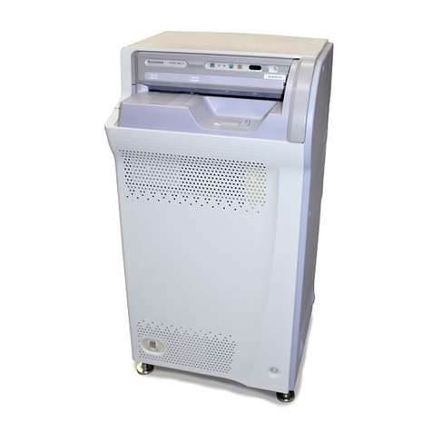
FujiFilm PROFECT CS User manual

- 1 -
Checkpoints When Trouble Occurs
Documents and References to be Used When Trouble Occurs
Image Related Checkpoints
Parts Related Checkpoints
Checkpoints during Installation
Checkpoints during Preventive Maintenance
Software Related Checkpoints
Search the error code.
The LCD panel does not transition to its default screen.
Connection is not established between RU and CL.
Distinguish between abnormal images.
Abnormal image occurs.
Gather log data.
Software Control (relationship with CR Console)
System Block Diagrams
Electrical Block Diagrams/Short-Circuit Detection
Circuit Diagrams (Disconnection check)
I/O Locations and Their Functional Overview
SNS17B Board LEDs
DRV17A/17B Board LEDs
Unit Locations
Roller Locations/Conveyance Paths
Image Data Flows
Sensitivity/Shading Correction
Parts List (INDEX)
Installation Specications
Preparation for Installation
Installation Procedures (Mechanical)
Installation Procedures (Software Setup)
Installing Optional Items
When Installed in Patient Environment
Registering the Master CL
Preventive Maintenance Programs
List of Preventive Maintenance Replacement Parts: 2-Year Intervals
3-Year Intervals
Procedures
Install/version update software and applications.
Gather log data.
Back up/restore machine shipment control data.
Back up/restore conguration data.
Machine Maintenance
RU PC-TOOL
MUTL
To Table of Contents of Service Manual
How to Use PDF Manual
GUIDE PAGE
GUIDE PAGE
PROFECT CS/ClearView CS/CS
m
Setting the Barcode Reader
RU/CL Software Setup Checkpoints
Voltage check

- 2 -
How to Use PDF Manual
Hyperlinks
A hyperlinks is inserted at the blue-colored mark in this manual.
Clicking it allows you to jump to the reference chapter or section.
-Example of Hyperlink-
{MC:3.1_Covers}
Clicking it allows you to jump to the reference section.

- 3 -
BLANK PAGE

- 4 -
BLANK PAGE

Printed in Japan
PROFECT CS/ClearView CS/CSm
CR-IR 363
Service Manual
No part of this publication may be reproduced, stored in a retrieval
system, or transmitted in any form or by means, electronic,
mechanical, photocopying, recording or otherwise, without the prior
written permission of FUJIFILM Corporation.
FCR is a trademark or a registered trademark of FUJIFILM Corporation.
<No part of this manual may be reproduced or transmitted.>
Copyright © 2003-2012 FUJIFILM Corporation. All rights reserved.
The relationship between mR (milliroentgen), which is the
unit of radiation, and μC/kg (micro-coulomb/kilogram),
which is the SI derived unit of radiation, is as follows.
1 mR = 0.258μC/kg
FUJI COMPUTED RADIOGRAPHY
Document No. 011-202-11E
1st Edition - Oct. 10, 2003
Revised Edition - Jun. 29, 2012
"PROFECT CS" is a trade name used in Asia, Europe, Oceania, Africa and
Americas (except for the U.S.).
"ClearView CS/CSm" is a trade name used in the U.S.
#20001 or Later #50001 or Later

BLANK PAGE

CR-IR 363
Service Manual
0.1
0.1
011-202-06
10.02.2006 FM4977
1. Handling of This Manual
1.1 About This Manual
Scope
This Service Manual is applicable to Fuji Computed Radiography CR-IR 363. The
machine is categorized as Class 1 according to IEC classication.
Notation of Unit Symbols
For notation of unit symbols, metric units set forth in the International Systems of Units
(SI) are used, as a rule. However, metric units that are allowed in the Measurement
Law, not in the SI, are used in some cases.
1.2 Precautions for Handling of This Manual
1. FUJIFILM Corporation reserves all rights related to this manual.
2. This manual should be accessible only to technical service personnel authorized by
FUJIFILM Corporation.
3. Since this manual contains condential information of FUJIFILM Corporation, such
as the internal structure of the product, appropriate measures should be taken to
prevent illegal or inappropriate disclosure and/or use of this manual.
4. The following conducts are prohibited without prior written approval of FUJIFILM
Corporation:
- Copy or transcribe a whole or part of the contents of this manual.
- Disclose, furnish, lend, and/or transfer a whole or part of the contents of this
manual to persons other than the afore-described technical service personnel.
- Use a whole or part of the contents of this manual for purposes other than
technical servicing of the product.
5. Portions of the descriptions in this manual may be revised due to improvements on
the product.
1.3 About Notation in the Manual
Notation of cautions, warnings, etc.
The notation formats of "warning", "caution", "Instruction", "note", and "reference" are
shown below.
WARNING
Used when death or serious injury may occur if the instruction is not observed.
CAUTION
Used when minor or medium levels of physical injury may be incurred if the
instruction is not observed.
Also used when the machine may suffer serious trouble (such as unrecoverable
or difcult-to-recover trouble).
INSTRUCTION
Used when the machine may suffer damage, or any failure or malfunction may occur,
if the instruction is not observed.
NOTE
Used to indicate the matters that need attention during steps of the procedure.
REFERENCE
Used to indicate terminology or supplemental explanations.
Indication of Refer To
The " " mark is used to indicate the chapter or section you should refer to.
Its format is as indicated below.
{MC:9.1_Erasure conveyor unit}
Notation in the Manual
In this Service Manual, the CR-IR 363 is sometimes denoted simply as the RU (Reader
Unit), and the CR-IR346/348CL as the CL.

CR-IR 363
Service Manual
0.2
0.2
011-202-07
09.30.2008 FM5340
Notation of Symbols
- Check/Adjustment indicator:Indicates that it is necessary to check or adjust the
installation location when the part or component
removed is to be reinstalled.
This indicator is placed in the illustration that depicts
the procedures for removing the parts and components.
When you see this indicator, refer to its relevant
"Check/Adjustment Procedures."
- Half-punch indicator: Indicates that it is necessary to align the half-punches
when installing the parts or components.
However, it is not indicated for the half-punches for
improving ease of assembly or preventing erroneous
assembly procedures.
1.4 Servicing Instruments and Tools That
Require Inspection/Calibration
The machine should be installed and serviced by use of servicing instruments and
tools that have been regularly inspected and calibrated as appropriate.
If the machine were serviced using servicing instruments and tools that have not
been inspected and calibrated, proper performance of the machine could not be
guaranteed.
Servicing instruments and tools that require inspection/calibration are as listed below.
The inspection/calibration should be planned and performed in accordance with the
specications and instruction manuals of the applicable servicing instruments and
tools.
Instruments and Tools That Require Inspection/Calibration
Name Inspection Calibration
Dosimeter -
Steel rule (150 mm) -
Steel rule (300 mm) -
Digital multimeter
Calipers ()-
: A block gauge for use in inspection requires calibration.
1.5 Caution when Using the ST-BD Type IP
When using the ST-BD type IP, be sure to use the equipment which is installed with
the software version V2.0 or later and on which the image adjustment is performed
with the IP and the cassette.

CR-IR 363
Service Manual
011-202-09E
10.24.2011 FM5964
0.3
0.3
CR-IR 363 Service Manual - Contents
Contents Safety Precautions
Safety Precaution
1. Safety Precautions.................................................................. 1
1.1 General Precautions........................................................................1
1.2 Precautions Against Laser Radiation ..............................................2
1.3 Precautions on Patient Environment ...............................................2
2. Labels....................................................................................... 3
2.1 Laser Precaution Labels..................................................................3
2.1.1 Laser Precaution Label Attachment Locations............................................3
2.1.2 List of CR-IR 363 Laser Precaution Labels.................................................4
2.2 Other Labels....................................................................................7
2.2.1 Attachment Locations for Ratings Indication Label and Other Labels ........7
2.2.2 Handling Instruction Labels and Attachment Locations ............................10
3. Protective Housings Against Laser Exposure ................... 14
4. CLASSIFICATION .................................................................. 14
5. Cautions on Electromagnetic Waves .................................. 15
5.1 Electromagnetic Compatibility (EMC)............................................15
5.1.1 Further Information for IEC60601-1-2.......................................................15
6. CONNECTABLE PERIPHERALS .......................................... 18
7. Cautions on Network ............................................................ 19

CR-IR 363
Service Manual
011-202-05
05.09.2005 FM4610
0.4
0.4
Contents Product Specications
Product Specications
1. Specications of Machine ...................................................... 1
1.1 Product Code ..................................................................................1
1.2 Available IP Sizes and Types ..........................................................1
1.3 List of Optional Items.......................................................................2
1.4 Product Specications.....................................................................2
1.5 Dimensions, Weight, and Center of Gravity ....................................2
1.6 Means for Moving and Fixing the Machine......................................3
1.7 Environmental Conditions ...............................................................3
1.8 Electrical Specications...................................................................4
1.9 Installation Space and Servicing Space ..........................................4
1.10 Disposal...........................................................................................5
1.10.1 Disposal of Machine....................................................................................5
1.10.2 Disposal of IP..............................................................................................5

CR-IR 363
Service Manual
0.5
0.5
Contents Machine Description (MD)
011-202-11E
06.29.2012 FM6046
Machine Description (MD)
2.6 Bootup Processing .................................................................MD-27
2.7 RU Shutdown Processing ......................................................MD-29
3. Descriptions of Electrical Operations .......................... MD-30
3.1 Power Supply Voltage Output Detection Function .................MD-30
3.2 Erasure Unit Control ..............................................................MD-39
3.2.1 Overview of the Erasure Unit Control
(#20001 or later)................................................................................. MD-39
3.2.2 Components of the Erasure Unit Control (#20001 or later)................ MD-39
3.2.3 Overview of the Erasure Unit Control
(#50001 or later)................................................................................. MD-40
3.2.4 Components of the Erasure Unit Control
(#50001 or later)................................................................................. MD-41
3.2.5 ErasureLampandBoardCongurations
(#50001 or later)................................................................................. MD-42
3.3 LEDs on the SNS17B Board ..................................................MD-43
3.3.1 Meaning of LED ON (Illuminated) ...................................................... MD-43
3.3.2 Correspondence between LEDs and Sensors................................... MD-43
3.3.3 Correspondence between LEDs and Erasure Control Signals
and FFM Control Signals ................................................................... MD-45
3.4 LEDs on the DRV17A/DRV17B Boards .................................MD-46
3.4.1 Correspondence between LEDs and Loads ...................................... MD-46
3.4.2 Meaning of LED ON (Illuminated) ...................................................... MD-47
4. Descriptions of Scanner Mechanism and
Its Operation ................................................................... MD-48
4.1
Descriptions of CR-IR 363 Scanner Operation........................... MD-48
4.1.1 Scanner Controller Unit Operation Sequence.................................... MD-48
4.1.2 Respective Correction Data ............................................................... MD-49
4.1.3 Relationship between Subscan Motor Speed,
Polygon Rotation Speed, and IP Type/Reading Mode....................... MD-49
1. Machine Overview............................................................ MD-1
1.1 Features ...................................................................................MD-1
1.2 SystemConguration ...............................................................MD-1
1.3 OverallMachineCongurationandComponentNames ..........MD-2
1.4 Machine Components ..............................................................MD-4
1.4.1 Unit Locations ...................................................................................... MD-4
1.4.2 Roller Locations and Conveyance Paths ............................................. MD-5
1.4.3 I/O Locations and Functional Descriptions........................................... MD-6
1.4.4 Board Locations ................................................................................. MD-12
1.5 System Block Diagram ...........................................................MD-13
2. Descriptions of Software Control ................................. MD-19
2.1 Network Settings ....................................................................MD-19
2.2 Data Flow between RU and CL..............................................MD-19
2.2.1 Data Flow during Routine Processing................................................ MD-19
2.2.2 "Install Operation" and Data Flow ...................................................... MD-20
2.2.3 "VERSION UP" Operation and Data Flow ......................................... MD-22
2.2.4 Flow of BACKUP Data ....................................................................... MD-23
2.2.5 Data Flow during Restore .................................................................. MD-23
2.3 Master CL Switching Function................................................MD-24
2.4 Error Handling ........................................................................MD-25
2.4.1 Error Handling.................................................................................... MD-25
2.4.2 Cases where Retry is Impossible (FATAL Error) ................................ MD-25
2.5 SLEEP Mode..........................................................................MD-25
2.5.1 Operation in SLEEP Mode................................................................. MD-25
2.5.2 Transition to the SLEEP Mode........................................................... MD-26
2.5.3 Recovery from SLEEP Mode ............................................................. MD-26

CR-IR 363
Service Manual
0.6
0.6
Contents Machine Description (MD)
011-202-11E
06.29.2012 FM6046
4.1.4 Image Data Flow................................................................................ MD-50
4.1.5 Error Detection/Processing Subsystem ............................................. MD-51
4.1.6 LED Indications of I/O Status............................................................. MD-52
5. Descriptions of Mechanical Components and Their
Operations ...................................................................... MD-53
5.1 Features of Components Used for Each Unit.........................MD-53
5.2 IP Conveyance Flow ..............................................................MD-56
5.3 Cassette Set Unit ...................................................................MD-57
5.3.1 Operation during IP Feed and Load................................................... MD-58
5.3.2 How to Detect the IP Size .................................................................. MD-60
5.4 Feed/Load Conveyor Unit ......................................................MD-61
5.4.1 Path Changeover Guide/Convergence Path Changeover Guide ...... MD-62
5.4.2 Brush Rollers...................................................................................... MD-64
5.5 Side-Positioning Conveyor Unit..............................................MD-65
5.5.1 Side-Positioning Mechanism.............................................................. MD-65
5.5.2 Cleaning Guides................................................................................. MD-65
5.6 Subscanning Unit ...................................................................MD-66
5.6.1 IP Stopper Mechanism....................................................................... MD-66
5.6.2 Dust Removal Mechanism ................................................................. MD-66
5.6.3 Reading Mode.................................................................................... MD-67
5.6.4 Center Guide and Grip Rollers........................................................... MD-67
5.7 Post-Reading Conveyor Unit..................................................MD-68
5.7.1 Movable Guide................................................................................... MD-68
5.8 Erasure Conveyor Unit ...........................................................MD-68
5.8.1 Switchback Mechanism...................................................................... MD-68
5.8.2 Side-Positioning Mechanism.............................................................. MD-69
5.8.3 Filter of Erasure Lamp........................................................................ MD-69
6. Nothing............................................................................ MD-70
7. Updated Contents of the Software Programs ............. MD-71
7.1 Changes in Updates...............................................................MD-71
7.2 Addition of Function of Reading IP Type ST-BD
(Only for CR-IR 363) ..............................................................MD-75
7.2.1 Outline of Function of Reading the IP Type ST-BD............................ MD-75
7.2.2 Preparation for Use of Function of Reading the IP Type ST-BD ........ MD-75
7.3 Nothing ...................................................................................MD-76
7.4 Deletion of the Secure Information from
theMachine-SpecicData .....................................................MD-77
7.5 Countermeasures to IP Overrun when
the Network Is Highly Loaded ................................................MD-78
7.5.1 Countermeasures against IP Overrun................................................ MD-78
7.5.2 Procedures of Changing the IPL Software Version............................ MD-78
7.6 Defective Erasure Lamp Detecting Function
and Improvement of Temperature Conditioning .....................MD-80
7.7 Addition of Function of Indicating
the Erasure Lamp Temperature..............................................MD-81
7.7.1 Indication of the Erasure Lamp Temperature ..................................... MD-81
7.7.2 Erasure Unit Thermal Sensor Display (MUTL)................................... MD-81
7.7.3 Indication of the Out-of-the Erasure Operating Range in
ERROR DB (ERROR DB).................................................................. MD-81
7.8 Addition of Function of Checking
the Conveyance Path Sensor.................................................MD-82
7.8.1 Sensors to Be Checked on the Conveyance Path............................. MD-82
7.8.2 MUTL Operation Window and the Results Indication ........................ MD-82
7.9 Countermeasure against Failures
inScannerMachine-SpecicDataBackup ............................MD-83

CR-IR 363
Service Manual
0.7
0.7
Contents Machine Description (MD)
011-202-11E
06.29.2012 FM6046
7.10 Addition of the Log Function of Checking the Erasure Dose..MD-85
7.10.1 OPER.LOG and Storage Folder......................................................... MD-85
7.10.2 Contents of OPER.LOG..................................................................... MD-85
7.11 Countermeasure against Abnormal Indication on
the ERROR DB ......................................................................MD-86
7.11.1 Abnormal Indication on the ERROR DB Window............................... MD-86
7.11.2 Countermeasure against Abnormal Indication on the ERROR DB .... MD-86
7.12 Countermeasure against the Whitened Image Display ..........MD-87

CR-IR 363
Service Manual
0.8
0.8
Contents Troubleshooting (MT)
011-202-04
11.15.2004 FM4425
Troubleshooting (MT)
4.10 Error Code Analysis Flow: Mechanism 10.............................. MT-68
4.11 Error Code Analysis Flow: Mechanism 11.............................. MT-69
4.12 Error Code Analysis Flow: Mechanism 12.............................. MT-70
4.13 Error Code Analysis Flow: Mechanism 13.............................. MT-71
4.14 Error Code Analysis Flow: Mechanism 14.............................. MT-72
4.15 Error Code Analysis Flow: Mechanism 15.............................. MT-73
4.16 Error Code Analysis Flow: Mechanism 16.............................. MT-74
4.17 Error Code Analysis Flow: Mechanism 17.............................. MT-76
4.18 Error Code Analysis Flow: Mechanism 18.............................. MT-77
4.19 Error Code Analysis Flow: Mechanism 19.............................. MT-79
4.20 Error Code Analysis Flow: Mechanism 20.............................. MT-80
4.21 Error Code Analysis Flow: Mechanism 21.............................. MT-81
4.22 Error Code Analysis Flow: Mechanism 22.............................. MT-82
4.23 Error Code Analysis Flow: Mechanism 23.............................. MT-83
4.24 Error Code Analysis Flow: Mechanism 24.............................. MT-85
4.25 Error Code Analysis Flow: Mechanism 25.............................. MT-86
4.26 Error Code Analysis Flow: Mechanism 26.............................. MT-87
4.27 Error Code Analysis Flow: Mechanism 27.............................. MT-88
4.28 Error Code Analysis Flow: Mechanism 28.............................. MT-89
4.29 Error Code Analysis Flow: Mechanism 29.............................. MT-90
4.30 Error Code Analysis Flow: Mechanism 30.............................. MT-91
4.31 Error Code Analysis Flow: Mechanism 31.............................. MT-92
4.32 Error Code Analysis Flow: Mechanism 32.............................. MT-93
4.33 Error Code Analysis Flow: Mechanism 33.............................. MT-94
1. Overview of Troubleshooting...........................................MT-1
1.1 Flow of Troubleshooting ........................................................... MT-2
1.2 Analysis and Check Flow Marks .............................................. MT-3
1.3 How to View "1.4 Troubleshooting with Error Log" ................... MT-4
1.4 Troubleshooting from Error Log................................................ MT-5
1.4.1 Checking the Error Log .........................................................................MT-5
1.4.2 Determining the Error Code of the Encountered Trouble......................MT-6
1.4.3 Viewing the Error Code Table to Locate the Associated Analysis Flow...MT-7
1.4.4 Viewing the Check Flows in Accordance with an Analysis Flow ...........MT-8
2. Error Code Table .............................................................MT-10
3. Detail Code ......................................................................MT-56
3.1 How to Understand Detail Code............................................. MT-56
3.2 Detail Codes for Scanner Errors ............................................ MT-57
4. Error Code Analysis Flow: Mechanism.........................MT-58
4.1 Error Code Analysis Flow: Mechanism 1................................ MT-58
4.2 Error Code Analysis Flow: Mechanism 2................................ MT-59
4.3 Error Code Analysis Flow: Mechanism 3................................ MT-61
4.4 Error Code Analysis Flow: Mechanism 4................................ MT-62
4.5 Error Code Analysis Flow: Mechanism 5................................ MT-63
4.6 Error Code Analysis Flow: Mechanism 6................................ MT-64
4.7 Error Code Analysis Flow: Mechanism 7................................ MT-65
4.8 Error Code Analysis Flow: Mechanism 8................................ MT-66
4.9 Error Code Analysis Flow: Mechanism 9................................ MT-67

CR-IR 363
Service Manual
0.9
0.9
Contents Troubleshooting (MT)
011-202-04
11.15.2004 FM4425
4.34 Error Code Analysis Flow: Mechanism 34.............................. MT-95
4.35 Error Code Analysis Flow: Mechanism 35.............................. MT-96
4.36 Error Code Analysis Flow: Mechanism 36.............................. MT-97
4.37 Error Code Analysis Flow: Mechanism 37.............................. MT-98
4.38 Error Code Analysis Flow: Mechanism 38.............................. MT-99
4.39 Error Code Analysis Flow: Mechanism 39............................ MT-100
4.40 Error Code Analysis Flow: Mechanism 40............................ MT-101
4.41 Error Code Analysis Flow: Mechanism 41............................ MT-102
4.42 Error Code Analysis Flow: Mechanism 42............................ MT-103
4.43 Error Code Analysis Flow: Mechanism 43............................ MT-104
4.44 Error Code Analysis Flow: Mechanism 44............................ MT-105
5. Error Code Analysis Flow: Scanner ............................MT-106
5.1 Error Code Analysis Flow: Scanner 1................................... MT-106
5.2 Error Code Analysis Flow: Scanner 2................................... MT-107
5.3 Error Code Analysis Flow: Scanner 3................................... MT-108
5.4 Error Code Analysis Flow: Scanner 4................................... MT-109
5.5 Error Code Analysis Flow: Scanner 5....................................MT-110
5.6 Error Code Analysis Flow: Scanner 6....................................MT-111
5.7 Error Code Analysis Flow: Scanner 7....................................MT-112
5.8 Error Code Analysis Flow: Scanner 8....................................MT-113
5.9 Error Code Analysis Flow: Scanner 9....................................MT-114
5.10 Error Code Analysis Flow: Scanner 10..................................MT-115
5.11 Error Code Analysis Flow: Scanner 11..................................MT-116
5.12 Error Code Analysis Flow: Scanner 12..................................MT-117
5.13 Error Code Analysis Flow: Scanner 13..................................MT-118
5.14 Error Code Analysis Flow: Scanner 14..................................MT-119
5.15 Error Code Analysis Flow: Scanner 15................................. MT-120
5.16 Error Code Analysis Flow: Scanner 16................................. MT-121
5.17 Error Code Analysis Flow: Scanner 17................................. MT-122
5.18 Error Code Analysis Flow: Scanner 18................................. MT-123
5.19 Error Code Analysis Flow: Scanner 19................................. MT-124
6. Error Code Analysis Flow: Electrical ..........................MT-125
6.1 Error Code Analysis Flow: Electrical 1 ................................. MT-125
6.2 Error Code Analysis Flow: Electrical 2 ................................. MT-126
6.3 Error Code Analysis Flow: Electrical 3 ................................. MT-128
6.4 Error Code Analysis Flow: Electrical 4 ................................. MT-129
6.5 Error Code Analysis Flow: Electrical 5 ................................. MT-130
7. Troubleshooting the Errors that Cause the Inability to
Update the Software Version or Back Up the Machine
Shipment Control Data .................................................MT-131
7.1 Checking the IIS ................................................................... MT-131
7.2 Checking the Operating Status of the FTP Server ............... MT-132
7.3 Checking the IP Address of the CL....................................... MT-132
7.4 Checking "LIST OF EXISTING RU" ..................................... MT-133
7.5 Checking the FTP Server Address of the RU....................... MT-134

CR-IR 363
Service Manual
0.10
0.10
Contents Troubleshooting (MT)
011-202-11E
06.29.2012 FM6046
8. Procedures for Checking the Voltage .........................MT-135
8.1 Checking the Board Locations ............................................. MT-135
8.2 Checking the Voltage on the CPU91A Board Test Pins (TP1)... MT-135
8.2.1 Check Procedures.............................................................................MT-135
8.2.2 Checking the Voltage on Test Pins....................................................MT-136
8.3 Checking the Voltage on
the SCN17A/SCT17B/SCT17P Board Test Pins (CN5)........ MT-136
8.3.1 Check Procedures.............................................................................MT-136
8.3.2 Checking the Voltage on Test Pins....................................................MT-137
8.4 Checking the Voltage on
the DRV17A Board Test Pins (TP8)...................................... MT-138
8.4.1 Check Procedures.............................................................................MT-138
8.4.2 Checking the Voltage on Test Pins....................................................MT-138
8.5 Checking the Voltage on the Power Supply Unit
(PSU17A/PSU29A) .............................................................. MT-139
8.5.1 Check Procedures.............................................................................MT-139
8.5.2 Checking the Voltage on Test Pins....................................................MT-139
9. Procedures for Checking the Fuses............................MT-140
9.1 Checking the Fuse Locations ............................................... MT-140
9.1.1 Checking the Board Locations .........................................................MT-140
9.1.2 List of Reference Sections ................................................................MT-141
9.2 Power Supply Unit................................................................ MT-142
9.2.1 Check Flow .......................................................................................MT-142
9.2.2 Procedures for Checking the Power Supply Unit Fuse.....................MT-142
9.3 SNS17B Board ..................................................................... MT-143
9.3.1 Check Flow .......................................................................................MT-143
9.3.2 Procedures for Checking the SNS17B Board Fuses ........................MT-143
9.4 DRV17A/B Board ................................................................. MT-144
9.4.1 Check Flow .......................................................................................MT-144
9.4.2 Procedures for Checking the DRV17A Board Fuses ........................MT-145
9.4.3 Procedures for Checking the DRV17B Board Fuses ........................MT-145
9.5 SCN17A/SCT17B Board ...................................................... MT-146
9.5.1 Check Flow .......................................................................................MT-146
9.5.2 Procedures for Checking the SCN17A/SCT17B Board Fuses..........MT-146
9.6 INV17A/B Board ................................................................... MT-147
9.6.1 Check Flow .......................................................................................MT-147
9.6.2 Procedures for Checking the INV17A Board Fuses ..........................MT-147
9.6.3 Procedures for Checking the INV17B Board Fuses..........................MT-148
9.7 Checking the Fuse ............................................................... MT-148
9.8 Checking the Cable .............................................................. MT-148
10. Procedures for Checking the Sensors........................MT-149
10.1 Checking the Sensors .......................................................... MT-149
10.2 Starting and Exiting the Monitoring Function........................ MT-150
10.2.1 Starting the Monitoring Function .......................................................MT-150
10.2.2 Exiting the Monitoring Function.........................................................MT-150
10.3 Checking via the LEDs on the SNS17B Board..................... MT-151
10.3.1 Procedures for Starting the LED Check............................................MT-151
10.3.2 Procedures for Exiting the LED Check..............................................MT-151
10.4 Sensor Check Flow 1 ........................................................... MT-152
10.4.1 Check Procedures via Monitoring Function (1).................................MT-153
10.4.2 Check Procedures via LEDs on the SNS Board (1)..........................MT-154
10.5 Sensor Check Flow 2 ........................................................... MT-155
10.5.1 Check Procedures via Monitoring Function (2).................................MT-156
10.5.2 Check Procedures via LEDs on the SNS Board (2)..........................MT-157

CR-IR 363
Service Manual
0.11
0.11
Contents Troubleshooting (MT)
011-202-04
11.15.2004 FM4425
10.6 Sensor Check Flow 3 ........................................................... MT-158
10.6.1 Check Procedures via Monitoring Function (3).................................MT-159
10.6.2 Check Procedures via LEDs on the SNS Board (3)..........................MT-160
10.7 Sensor Check Flow 4 ........................................................... MT-161
10.7.1 Check Procedures via Monitoring Function (4).................................MT-162
10.7.2 Check Procedures via LEDs on the SNS Board (4)..........................MT-163
10.8 Sensor Check Flow 5 ........................................................... MT-164
10.8.1 Check Procedures via Monitoring Function (5).................................MT-165
10.8.2 Check Procedures via LEDs on the SNS Board (5)..........................MT-166
10.9 Sensor Check Flow 6 ........................................................... MT-167
10.9.1 Check Procedures via Monitoring Function (6).................................MT-168
10.9.2 Check Procedures via LEDs on the SNS Board (6)..........................MT-169
10.10 Sensor Check Flow 7 ........................................................... MT-170
10.10.1 Check Procedures via Monitoring Function (7).................................MT-171
10.10.2 Check Procedures via LEDs on the SNS Board (7)..........................MT-172
10.11 Sensor Check Flow 8 ........................................................... MT-173
10.11.1 Check Procedures via Monitoring Function (8).................................MT-174
10.11.2 Check Procedures via LEDs on the SNS Board (8)..........................MT-175
10.12 Sensor Check Flow 9 ........................................................... MT-176
10.12.1 Check Procedures via Monitoring Function (9).................................MT-177
10.12.2 Check Procedures via LEDs on the SNS Board (9)..........................MT-178
10.13 Sensor Check Flow 10 ......................................................... MT-179
10.13.1 Check Procedures via Monitoring Function (10)...............................MT-180
10.13.2 Check Procedures via LEDs on the SNS Board (10)........................MT-181
10.14 Sensor Check Flow 11 ......................................................... MT-182
10.14.1 Check Procedures via Monitoring Function (11) ...............................MT-183
10.14.2 Check Procedures via LEDs on the SNS Board (11) ........................MT-184
10.15 Sensor Check Flow 12 ......................................................... MT-185
10.15.1 Check Procedures via Monitoring Function (12)...............................MT-186
10.15.2 Check Procedures via LEDs on the SNS Board (12)........................MT-187
10.16 Sensor Check Flow 13 ......................................................... MT-188
10.16.1 Check Procedures via Monitoring Function (13)...............................MT-189
10.16.2 Check Procedures via LEDs on the SNS Board (13)........................MT-190
10.17 Sensor Check Flow 14 ......................................................... MT-191
10.17.1 Checking with a Scanner Board LED................................................MT-192
10.18 Barcode Reader Check Flow ............................................... MT-193
10.18.1 Check Procedures via Monitoring Function (14)...............................MT-194
10.19 Sensor Check Flow 15 ......................................................... MT-195
10.19.1 Check Procedures via Monitoring Function (15)...............................MT-196
10.19.2 Check Procedures via LEDs on the SNS Board (15)........................MT-197
10.20 Sensor Check Flow 16 ......................................................... MT-198
10.20.1 Check Procedures via Monitoring Function (16)...............................MT-199
10.20.2 Check Procedures via LEDs on the SNS Board (16)........................MT-200
10.21 Sensor Check Flow 17 ......................................................... MT-201
10.21.1 Check Procedures via Monitoring Function (17)...............................MT-202
10.21.2 Check Procedures via LEDs on the SNS Board (17)........................MT-203
11. Procedures for Checking the Motors ..........................MT-204
11.1 Checking the MA1, MA2, MA3, and MA4 Operation ............ MT-205
11.2 Checking the MB1, MB2, and MC3 Operation ..................... MT-206
11.3 Checking the MB3 Operation ............................................... MT-207
11.4 Checking the MC1 Operation ............................................... MT-208
11.5 Checking the MC2 Operation ............................................... MT-209
11.6 Checking the MC4 Operation ............................................... MT-210

CR-IR 363
Service Manual
0.12
0.12
Contents Troubleshooting (MT)
011-202-07
09.30.2008 FM5340
11.7 Checking the MZ1 Operation ................................................MT-211
11.8 Checking the MZ2 Operation ............................................... MT-213
11.9 Checking the MZ3 Operation ............................................... MT-214
11.10 Checking the MZ4 Operation ............................................... MT-215
11.11 Checking the MD1 Operation ............................................... MT-216
11.12 Checking the MD2 and ME1 Operation................................ MT-217
11.13 Checking the ME2 Operation ............................................... MT-218
11.14 Checking the ME3 Operation ............................................... MT-219
11.15 Checking the Motor Resistance Values................................ MT-220
12. Procedures for Checking the Actuators .....................MT-221
12.1 Checking the SOLA1, SOLA2, SOLA3,
and SOLA4 Operation .......................................................... MT-222
12.1.1 Visual Check Procedures..................................................................MT-223
12.1.2 Procedures for Checking the Cassette Hold Solenoid......................MT-224
12.1.3 Procedures for Checking the LED on the DRV Board ......................MT-225
12.2 Checking the PA1, PA2, PA3, and PA4 Operation ............... MT-226
12.3 Checking the SVA1, SVA2, SVA3, and SVA4 Operation...... MT-227
12.4 Checking the CLA1, CLA2, CLA3, and CLA4 Operation...... MT-228
12.5 Checking the SOLE1 Operation ........................................... MT-229
12.6 Checking the Actuator Resistance Values............................ MT-230
13. Procedures for Checking the Scanner I/O..................MT-231
13.1 Scanner I/O Check Flow ...................................................... MT-231
13.2 Checking Laser ON in MUTL................................................ MT-232
13.3 Checking the Cable .............................................................. MT-233
13.4 Checking the PMT/PMR....................................................... MT-234
14. Line Error between CL and RU ....................................MT-235
14.1 Analysis Flow for Line Error between CL and RU ................ MT-235
14.2 Checking Connection from the CL........................................ MT-236
14.3 CheckingCongurationInformationoftheCL...................... MT-237
14.4 Checking the IP Address of the CL....................................... MT-238
14.5 Checking the IP Address of the Master CL........................... MT-239
14.6 Checking the IP Address of the RU...................................... MT-240
14.7 Loopback Test ...................................................................... MT-241
14.7.1 Loopback Test Flow ..........................................................................MT-241
14.7.2 Loopback Test Procedure .................................................................MT-241
14.7.3 Loopback Test - 1..............................................................................MT-242
14.7.4 Loopback Test - 2..............................................................................MT-242
14.7.5 Loopback Test - 3..............................................................................MT-243
15. Troubleshooting Procedures
for Image Abnormalities ...............................................MT-244
15.1 Vertical Streaks .................................................................... MT-244
15.2 Horizontal Streaks ................................................................ MT-246
15.2.1 Analysis Flow for Horizontal Streaks.................................................MT-246
15.2.2 Troubleshooting Image Abnormalities Considered
to be Caused by IP............................................................................MT-246
15.2.3 Analyzing Pale Nonuniformity at the Leading Edge
or Trailing Edge of the IP...................................................................MT-247
15.2.4 Analyzing Thin, Distinct Nonuniformity..............................................MT-249
15.2.5 Procedures for Checking the Grip Roller (Upper) .............................MT-249
15.2.6 Procedures for Checking the Grounding of the PMT/PMR ...............MT-250
15.2.7 Procedures for Checking the FFM Motor..........................................MT-250
15.3 Other Abnormal Images ....................................................... MT-252

CR-IR 363
Service Manual
0.13
0.13
Contents Troubleshooting (MT)
011-202-07
09.30.2008 FM5340
15.4 Countermeasure against Image Abnormalities Due
to Laser Light Blocked under a Low Temperature................ MT-254
15.5 Countermeasure against Image Abnormality
of White-Black-White............................................................ MT-254
15.6 Countermeasure against Image Abnormalities like
Annual Rings ........................................................................ MT-255
16. Removing the IP ............................................................MT-256
16.1 Removing the IP from the Feed/Load Conveyor Unit........... MT-256
16.1.1 When the IP is Jammed in the Cassette Set Unit .............................MT-256
16.1.2 When the IP is Jammed in the Side-Positioning Conveyor Unit .......MT-257
16.2 Removing the IP from the Erasure Conveyor Unit ............... MT-259
16.2.1 When the IP is Jammed in the Subscanning Unit
or Post-Reading Conveyor Unit ........................................................MT-259
16.2.2 When the IP is Jammed in the Erasure Conveyor Unit.....................MT-261
17. Block Diagrams .............................................................MT-263
17.1 BCRA1, BCRA2, LED17A .................................................... MT-263
17.2 BCRA3, BCRA4, BCRC1, LED17A...................................... MT-263
17.3 LCD17A, LDD12A, SYN12A, POL17A................................. MT-264
17.4 Sensors (SA1 to SA12) ........................................................ MT-265
17.5 Sensors (SA13 to SA24) ...................................................... MT-266
17.6 Sensors (SC1 to SC4, SG1 to SG2, SD1 to SD2,
SE1 to SE2, SE4 to SE5) ..................................................... MT-267
17.7 Sensors (SB1 to SB11) ........................................................ MT-268
17.8 Sensors (SZ1 to SZ5) and FFM Motor (MZ1) ...................... MT-269
17.9 Motors
(MA1 to MA4, MD1 to MD2, ME1, ME3, MZ2 to MZ3)......... MT-270
17.10 Motors (MB1 to MB3, MC1 to MC4, ME2, MZ4) .................. MT-271
17.11 Actuators (SOLA1 to SOLA4, PA1 to PA4,
SVA1 to SVA4, CLA1 to CLA4) ............................................ MT-272
17.12 Actuator (SOLE1) ................................................................. MT-273
17.13 Erasure Lamps and Fan 1.................................................... MT-274
17.14 Erasure Lamps and Fan 2.................................................... MT-275
18. Board Test in MUTL ......................................................MT-276
18.1 Analysis Flow ....................................................................... MT-276
18.2 Board Test ............................................................................ MT-277
18.2.1 All Board............................................................................................MT-278
18.2.2 CPU Board........................................................................................MT-279
18.2.3 IMG Board.........................................................................................MT-280
18.2.4 SCN/SCT Board................................................................................MT-281
18.2.5 SNS/DRV Board................................................................................MT-282
18.2.6 INV Board..........................................................................................MT-283
19. Gathering Various Data When Trouble Occurs ..........MT-284
20. Troubleshooting Failures where Error Code
Is Undetectable and Machine does not Boot Up........MT-285
20.1 Analysis Flow for Bootup Failure.......................................... MT-285
20.2 Checking the LEDs on the IMG Board and CPU Board ....... MT-286
20.3 Checking the DIP SW Setting on the CPU91A Board .......... MT-287
20.3.1 Checking the DIP SW Setting of the CR-IR 363 ...............................MT-287
20.4 Procedures for Restoring the RU Application....................... MT-288
20.4.1 Procedures for Restoring the RU Application....................................MT-288
20.4.2 Touch Panel Calibration Procedures.................................................MT-296

CR-IR 363
Service Manual
0.14
0.14
Contents Troubleshooting (MT)
011-202-07
09.30.2008 FM5340
20.5 Checking the Connector Connections.................................. MT-298
20.6 Checking the LCD Panel ...................................................... MT-298
20.7 Check of Cable Connection and Continuity.......................... MT-299
20.7.1 Check Flow .......................................................................................MT-299
20.7.2 Checking the LED on the Power Supply Unit....................................MT-300
20.7.3 Checking Connection of the IMG Board Connector..........................MT-300
20.7.4 Checking for Continuity of the Cables 1............................................MT-301
20.7.5 Checking for Continuity of the Cables 2............................................MT-301
20.7.6 Checking for Continuity of the Cables 3............................................MT-302
21. Troubleshooting Failures of New IP ............................MT-303
22. Checking the Status of Each Unit................................MT-304
22.1 Checking the Cassette Set Unit ........................................... MT-304
22.2 Checking the Erasure Conveyer Unit -1............................... MT-306
22.2.1 Checking the Tab of the Timing Belt Wheel ......................................MT-306
22.2.2 Checking the Housing and the Bearing.............................................MT-307
22.2.3 Checking the Tension Coil Spring .....................................................MT-307
22.3 Checking the Erasure Conveyer Unit -2............................... MT-308
22.4 Checking the Connector on the Scanner Board................... MT-309
22.5 Checking the Connector on the Scanning Optics Unit ......... MT-309
22.6 Checking the Connector Connection between the Boards... MT-310
Appendix 1. Procedures for Restoring the Application by
means of DIP SW-No.6 of
the CPU91A Board ...................................Appx MT-1
1. Procedures for Restoring the RU Application.................. Appx MT-1
2. Touch Panel Calibration Procedures ............................. Appx MT-10
Appendix 2. Dimensions in the Conveyance Path...Appx MT-12
1. Rollers and Sensors Installed in the Conveyance Path .. Appx MT-12
2. General Dimensions of the Conveyance Path .............. Appx MT-12
3. Dimensions of Members in the Conveyance Path ........ Appx MT-13
This manual suits for next models
3
Table of contents
Other FujiFilm Laboratory Equipment manuals
Popular Laboratory Equipment manuals by other brands

Okolab
Okolab H301-PI-736-160x110 user manual

Agilent Technologies
Agilent Technologies 6890 Series operating manual

Endress+Hauser
Endress+Hauser analytikjena qTOWER operating manual

Agilent Technologies
Agilent Technologies DNA 1000 Kit quick start guide

Monmouth Scientific
Monmouth Scientific Ductaire TITAN DT1000 operating & maintenance manual

BANDELIN
BANDELIN Sonopuls HD 4050 operating instructions