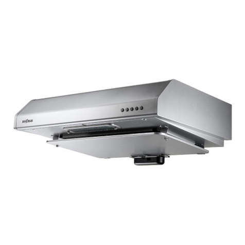
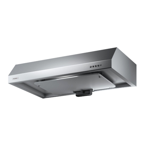
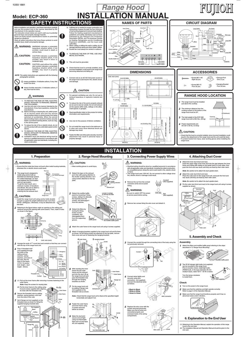
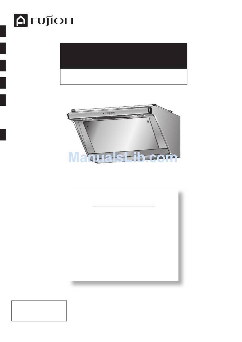
Fujioh FR-ST2190VP User manual

TABLE OF CONTENTS
Thank you very much for purchasing our cooker hood.
Please read this Manual thoroughly before installing/operating the
cooker hood.
Keep this Manual properly for future reference after reading.
To the sales shop/installer:
After installation, please
provide this Manual to the
user without fail.
Cooker Hood
Installation/Operation Manual
English page 1~20 酒悶嶄猟 21 ~40 匈繁體中文 41 ~ 60 頁
FR-ST2190VP
FR-ST2190VP-15
1F02 2782
*1F022782*
Safety Precautions ..................2~4
Precautions on Use......................4
Preparation ..............................5~7
Name of Parts..............................5
Switch ......................................6~7
Installation .............................8~12
Preparation and Check
before Installation...................8~9
Installing the cooker hood....10~12
Operation Check ........................12
Maintenance........................13~15
Precautions for Maintenance
......
13
Detaching/Attaching of Parts
to be Cleaned.....................13~15
Cleaning.....................................15
Other Information.................16~18
Specifications.............................16
Circuit Diagram ..........................17
Service and Warranty.................18

2
Safety Precautions
WARNING
Never attempt to disassemble, repair or modify.
Always seek help from a qualified technician. Otherwise, there may be fire, electric shock or
abnormal conditions.
Do not use in regions where the power voltage exceeds 220V/230V/240V AC.
Otherwise, there may be fire hazards or electric shock.
The cooker hood is intended to be installed over a hob with up to four hob elements
or burners.
Disassembly,
repair, or
modification
prohibited
Prohibitions
on Use
Less than
4 burners
Electric wiring shall be carried out properly by professional technician or personnel.
Incorrect wiring may cause electric leakage or fire hazards.
Caution
during
Assembly
Read the following Safety Precautions before installation and operation, and use the cooker hood properly
and securely.
These Safety Precautions are for correct operation of the product, preventing any harm or damage
to yourself or others. These Safety Precautions are classified into 2 categories ("WARNING" and
"CAUTION") depending on their hazard and severity. Please pay attention and strictly observe these
Safety Precautions as they are crucial to safety.
Safety Precautions
Be sure to disconnect the power plug from the outlet, or switch off the breaker during
maintenance. Also, never handle the power plug or breaker with wet hands.
Otherwise, there may be electric shock or physical injury.
Disconnect
the power
plug
The power plug shall be cleaned regularly to prevent dust accumulation.
Otherwise, there may be fire hazards or electric shock.
Never spray water on any electric parts.
Otherwise, there may be fire hazards or electric shock.
Dust removal
Spraying
water
prohibited
Installation work should be performed by a minimum of 2 persons.
The weight of the cooker hood is about 31kg.
Caution
during
Installation
Breakers shall be incorporated in the fixed wiring to ensure all-pole disconnection
from the main power source.
Caution
during
Installation
WARNING
CAUTION
Alerts possible risk of serious injury, if not observed.
Alerts possible risk of injury or physical damage, if not observed.
In case of a gas leak, do not switch on the cooker hood.
Otherwise, it may result in a gas explosion.
Operation
prohibited
The cooker hood shall be installed at a place with sufficient ventilation.
When using a natural exhaust type stove, poor ventilation may result in carbon monoxide
poisoning.
Attention to
ventilation
The air shall not be discharged into hot flues that are used for discharging fumes
generated from burning gas or other fuels (not applicable to cooker hoods that can
discharge the air back into the room).
Strict
implementation

3
Safety Precautions
Be sure to disconnect the power plug from the outlet, or switch off the breaker
when the cooker hood is idle for a long run.
Otherwise, it may result in the deterioration of the insulation property, as well as fire
hazards or electric shock.
Disconnect
the plug
Disconnect
the plug by
holding the
power plug
Never touch the fan guard or parts around it while cooking.
Otherwise, it may result in the detachment of the fan guard or parts, and even burns or
injury.
Caution
during
Installation
Prohibitions
on Use
Ensure that electric wiring is laid out safely according to the related standard or
regulations.
Incorrect wiring may result in fire or electrical shock.
Component parts removed while repairing shall be securely assembled.
Otherwise, there may be injury or damage caused by collapse of the cooker hood.
Prohibited
from Contact
Install the product in a stable location.
Otherwise, the cooker hood may detach and cause injury or damage.
When disconnecting the power, hold the power plug itself instead of the power cord.
Otherwise, it may result in the damage of the power cord, as well as fire hazards or
electric shock.
Caution
during
Assembly
Caution
during
Assembly
Prohibited
from Contact
During operation, never insert fingers or other objects into the cooker hood.
Otherwise, it may result in the machine failure or physical injury.
Never use the product in a wet place such as bath room (Exhaust fans should be
used in a bath room).
Otherwise, it may result in fire hazards or machine failure.
WARNING
CAUTION
Prohibited
Operation
Switch off the cooker hood immediately if the pan catches fire.
Otherwise, the cooker hood will fuel the fire and create a dangerous situation.
Always perform exhaust adjustments.
Attention to
adjustment
Ensure that there is sufficient ventilation in the room when using the cooker hood
with multiple appliances burning gas or other fuels.
Attention to
ventilation
Cleaning that is not carried out in accordance to Safety Precautions may result in a
fire hazard.
Clean
frequently
Never barbecue under the cooker hood.
BBQ
prohibited
The product is not intended for use by persons (including children) with reduced physical,
sensory or mental capabilities, or lack of experience or knowledge, unless they are under the
supervision or guidance of a specially assigned person who is responsible for their safety.
Children require extra supervision. Do not let children play with the product.
Supervision
Required
Caution
during
Installation
The distance between the topmost part of cooking appliance and the lowest part of
cooker hood, when it is located exactly over the cooking appliance, shall be 650mm
to 850mm. If greater distance is specified in the cooking appliance manual, it must
be taken into account.

4
Safety Precautions
Precautions on Use
Always turn on the cooker hood when cooking.
Otherwise, the cooker hood may be damaged or fail to operate due to the increased temperature.
Never use a gas hob without any cooking equipment on it.
Otherwise, the high temperature of the body of the cooker hood may result in machine failure.
Smoke capturing performance may be deteriorated by cross winds when the induction cooker is used.
Additionally, dew may form on the surface of the cooker hood when it is used at low temperature.
When this happens, first wipe off the cooker hood before using it.
Prevent direct wind from air conditioners.
Otherwise, the smoke capturing performance may be reduced by direct wind from an air conditioner.
The cooker hood is easily affected in open areas, especially when the induction cooker is not generating any
ascending air current.
Ensure that sufficient ventilation is maintained when operating the cooker hood.
Ensure that there are adequate air intake slots on the wall opposite from the cooker hood, or that the door of the room
is kept slightly open.
Otherwise, the smoke capturing performance may be reduced, or there may be abnormal noise, vibration.
Ensure that the distance between the water heater and the cooker hood is more than 500mm.
As the area surrounding the water heater is at higher temperature, the cooker hood shall be at least 500mm from the
water heater.
Never install the cooker hood above the water heater. Otherwise, the cooker hood may become damaged or fail due
to the increased temperature.
Never use the cooker hood with its rectifier panel removed.
Otherwise, the smoke capturing performance may be reduced.
Inoperable cooker hoods shall be processed to ensure that it cannot be used before it is disposed.
CAUTION
Strict
implementation
If the power cord is damaged, request for a replacement from the manufacturer, its
service agent or similarly qualified persons in order to avoid any hazards.
Prohibitions
Wear gloves
Caution
Caution
during
Installation
Caution
during
Installation
Prohibited
from Placing
Objects
Replace
damaged
power cord
Always wear gloves during maintenance.
Otherwise, the user may be injured by sharp edges or corners.
Clean the oil tray when the oil level reaches one half of the height to prevent the oil
from overflowing or dripping during removal.
Use the mounting bracket and plastic expansion pipes that come with the cooker
hood during installation (to concrete walls) for preventing the product from
detaching.
In order to prevent the product from detaching, the plastic expansion pipes shall be
used with the drill with corresponding specifications to ensure that the connection
is as seamless as possible.
Ensure that the exhaust pipe is connected to an outdoor area. To avoid fire hazards
and ensure the ventilation of fresh air, waste gas shall be discharged outdoors
instead of into walls, attics or garages.
Never put anything on the cooker hood.
Otherwise, it may result in fire hazards, machine failure or injury due to detachment.
Do not stare directly at the LED lights when they are turned on.

5
Preparation
Preparation
Duct cover
Slide duct co
ver
Switch
Oil tray
Fan guard
Oil panel
LED
Power plug
Rectifier pane
l
Name of Parts
Packing List
Name Usage Quantity
Main unit
—1
Rectifier panel
—1
Exhaust pipe (diameter ∅180mm) —1
Slide duct cover —1
Duct cover —1
Mounting bracket Fixed main unit 1
Plastic expansion pipe Fixed mounting bracket and duct cover fixing bracket 7
Washer-head wood screw (∅5.1×45) Fixed mounting bracket and duct cover fixing bracket 7
Duct cover fixing bracket Fixed slide duct cover 1
Flat-head screw (M4×8) Fixed slide duct cover 2
Exhaust port Connecting the main unit and the exhaust pipe 1
Installation screw (M4 ×16) Connecting the main unit and the exhaust port 4
Installation screw (∅3×8) Connecting the exhaust port and the exhaust pipe 2
Oil tray Collect used oil 1
The following is only applicable to FR-ST2190VP-15
Duct reducer (∅180-∅150) Connecting the exhaust pipe and the exhaust hose 1
Soft tape Sealing the exhaust port and the exhaust pipe 2

6
Preparation
Switch
Off Switch
Press down this switch to immediately turn off
the impeller.
* The lights will still remain ON. Press to turn
them off.
It shows the state when switch is locked
Flash
alternately
Beep
three
times
When the switch is locked, the unit will
display its state when any other button
except “OFF” is pressed.
Flash in order
Press and hold
(about 3s)
Beep
Switch locking (disable all functions)
To lock switches
Press for 3s.
---When the unit “beeps” twice, the switch will
be locked.
---When the impeller stops, the lights will turn
off.
--- and flash alternately.
Press any other switches except in the
locking state.
---The unit “beeps” three times. The lights
flash at the order of .
---Both the impeller and the lights turn off.
To unlock switches
Press and hold it for 3s until the unit
“beeps” again.
After unlocking, readjusting of the light,
operation and airflow switches as required.
* Always ensure that cooking is complete,
and that the cooker hood has cooled down
completely before locking.
* The locking state is cancelled in case of
power outrage or tripping.
Beep
twice
Press and hold
(about 3s)

7
Preparation
Auto Switch Off function to ensure that the operation is stopped
The cooker hood stops operation automatically 5h after the last operation is completed. The lights will
also be turned OFF. Press any of the switches to start it again.
Entering boost mode
Press and hold the switch (3s) during operation to
enter the boost mode.
Automatically return to (high) after operating for 5min.
---Light flashes during boost.
Exiting boost mode
Press any switch ( or ) or press and hold switch
(for 3s) to exit from boost mode and enter to normal
mode.
---Any of the lights flashes.
* Press to exit boost mode operation.
Setting 3min timer operation
Press the lit up airflow switch during operation to set
the 3min timer operation.
---Light flashes.
Each time when the switch is pressed, the 3min timer
operation can be activated and deactivated.
* Light remains ON.
---The 3min timer operation setting is switched to
boost mode 5s before the shutdown of the 3min
timer operation.
---Lights flash.
Operation and airflow switches
(low, medium, high)
When pressing down this switch, the switch will light up, and the airflow can be adjusted.
Light switch
Press this switch to turn on/off the light.
(Low) .......... For low amount of smoke,
or quiet operation.
(Medium) .... Normal operation.
(High).......... For high amount of smoke,
or rapid ventilation.
Beep
Beep
Beep
Press and hold
(for about 3s)
Beep
Beep

8
Installation
Checking mounting surface strength
The mounting surface should have sufficient strength to support the cooker hood. The cooker hood
shall be installed on a location that can support the weight of the cooker hood for an extended period
of time. (Product weight: 31kg)
In the case of boarded wall
If the thickness is more than 20mm, mount the cooker hood directly to the wall.
If the thickness is less than 20mm, embed a reinforcing board and mount the cooker hood to the
board.
In the case of a concrete/tile faced wall
Use the plastic expansion pipes that come with the unit.
Installation
1. Install the cooker hood carefully and avoid any contact with any metal parts (the metal
lattice in the wall or the like) of the building.
2. Never embed the body of the cooker hood in the wall. Otherwise, it may result in the electric
leakage of the unit.
3. The air shall not be discharged into hot flues that are used for discharging fumes generated
from burning gas or other fuels (Not applicable to cooker hoods that can discharge the air
back into the room).
4. The distance between the topmost part of cooking appliance and the lowest part of cooker
hood, when it is located exactly over the cooking appliance, shall be 650mm to 850mm. If
greater distance is specified in the cooking appliance manual, it must be taken into account.
5. Use a gas hob with a width less than that of the cooker hood.
6. Avoid using the cooker hood with changes in specifications, for instance, with modified
switches.
7. Never install the cooker hood in a wet area or in other wet rooms since it may result in
electric shock or damage.
8. Never install the cooker hood at a place where the ambient temperature exceeds 40°C,
otherwise it may result in machine failure.
9. To protect your hands from injury, please wear working gloves when installing the cooker
hood.
10. If the power cord is damaged, it shall be replaced by the manufacturer or its service agent
or a similarly qualified person to prevent any hazard.
CAUTION
Checking Accessory Parts
Take out the main unit and accessory parts (e.g. exhaust port, duct cover) from the packing box, and check
if all accessories described in the packing list are available.
Power plug
The cooker hood uses a 3-phase power plug.
Be sure to use the wall outlet specified for the cooker hood.
Preparation and Check before Installation

9
Installation
895
650~850
650~850
650~1000
650~1000
151
83
895
Exhaust pipe Ceiling
Exhaust pipe
Ceiling
Top view
Confirmation of the installation location
(Unit: mm)
Attaching exhaust port
Align the exhaust port with the screw hole on the top of
the cooker hood and secure with 4 installation screws
(M4×16) (See figure on the right).
Note
When attaching the exhaust port, pay attention to
the shutter opening direction.
If installed incorrectly, it may result in poor discharge
or abnormal noise, etc.
Installation screw
(M416)
Exhaust port

10
Installation
Installing the cooker hood
Washer-head
wood screw
⾸ĝ5.145⾹
Duct cover
fixing bracket
Mounting
bracket
Tensioning
and securing
Washer-head
wood screw
⾸ĝ5.145⾹
Exhaust pipe
Projection
Projection
1)Secure the mounting bracket and duct cover fixing
bracket on the wall with 6 washer-head wood screws
(∅5.1×45) (as shown below).
When using plastic expansion pipes, use a drill with a
∅8mm bit to drill holes in the wall. The holes shall have
a diameter of 8mm and depth over 55mm.
2) Attach the product to the mounting bracket.
3) To prevent the product from disconnecting from the
mounting bracket, please secure it with a washer-
head wood screw (∅5.1×45) at the ※part (referring
to the figure above).
When using plastic expansion pipes, secure the
product to the wall using washer-head wood screws
as mentioned before.
100
300
30
515 35
350
20
øPart
Note
Please disconnect the breaker on the power
distribution panel when inserting the power plug.
Please shorten the exhaust pipe as far as possible.
Ensure that there are no depressions or other kinds
of deformation.
4) Align the 4 projections of the exhaust pipe with the
projections of the exhaust port. Insert and slightly
rotate counterclockwise.
5)Secure the exhaust port to the exhaust pipe with 2
(∅3×8) screws.
6) Please make sure that the breaker is switched to the
“OFF” position before connecting the power plug to
the socket.
Installation screw
⾸ĝ38⾹
Exhaust pipe

11
Installation
Exhaust pipe
Projection Projection
Flat head screw
(M48)
Slide duct cover
8)Slide the slide duct cover to the upper
position, hang onto the duct cover fixing
bracket, and secure with 2 flat head screws
(M4×8) laterally.
Duct co
ver
7) Embed the duct cover into the slot on the top of
the cooker hood.
Take care not to damage the product during
installing.
1) The upper and lower ends of the duct reducer
(∅180-∅150) shall be attached with a soft tape
and then connected to the exhaust pipe.
2) Using a non-flammable tape (such as
commercially available aluminum tape), the
connections between the exhaust opening,
duct reducer and exhaust duct shall be joined
and sealed together tightly without any gap.
Duct reducer
⾸
ĝ180-ĝ150⾹
Soft tape
Exhaust pipe
Duct reducer
⾸
ĝ180-ĝ150⾹
Taping with
non-flammable mater
ials
(Aluminum tape etc.)
(Only applicable to FR-ST2190VP-15)

12
Installation
Operation Check
11) After installing, pull the rectifier panel up and
down to make sure it will not drop.
Make sure it is
firmly locked.
Note
In order to prevent falling due to insufficient locking,
please make sure that the rectifier panel is locked
securely.
12) Install the oil tray on the rectifier panel.
Align the 2 projections of the oil tray with the
installation hooks of the rectifier panel. Insert the
projections, slide the tray backward and secure it.
Hook
Move the distributor to “ON” for trial operation. Refer to Page 6 and Page 7 for instructions on switch
operation and operation state confirmation.
Check if the impeller rotates normally at all speeds during operation.
Check that there are no abnormal noise or vibration.
9) Securely hang the left and right hooking bracket
at the rear of the rectifier panel on the hanging
bracket ( ①) of the cooker hood.
10) Support the rectifier panel with both hands and
lift the front end upwards until a “snap” sound is
heard and it is secure ( ②).
ŋ
Close
Ō
Hanging bracket
Hooking bracket

13
Maintenance
• Beforecleaningthecookerhood,besuretodisconnectthepowerplugfromthesocket,
or turn off the breaker.
• Forsafety,alwayswearapairofrubbergloveswhilecleaningthefanguardandother
parts.
• Especially,takecaretoensurethatnowaterissplashedonelectricparts
such as the motor, switches, connectors or the like. Do not spray any type
of detergent to the electric parts. Otherwise, it may cause machine failure.
• Donotapplysolventssuchasthinner,benzene,polishingpowderorthelikeforcleaningpaintedsurfaces,
oil panel and others, since it will tarnish or scratch them.
• Donotwashpartswithahardbrushorthelikeforcleaning,otherwise,partswillbedamaged.
• ThecookerhoodmaycatchreifitisnotcleanedaccordingtotheManual.
Clean the cooker hood frequently as it will become very dirty (Especially, clear the fan guard at least once a
month. For a family cooking at least twice a day, clean the fan guard once every two weeks).
If the cooker hood is left unattended for a long time, a large amount of oil will accumulate and become
hardened grease, which is difficult to remove.
Always clean the oil tray, around the cooker hood and the rectifier panel in a timely manner in case of any
oil staining (cleaning frequency: about once a month).
Install all parts using the opposite procedure as that for removing the parts.
Precautions for Maintenance
Maintenance
Detaching/Attaching of Parts to be Cleaned
Detaching the oil tray
Remove the oil tray straight out from the unit hook while
keeping it level to prevent the oil from overflowing.
Hang the oil tray on the hook and push it to the deepest
part of the unit during installing.
Note
Oil may not accumulate in the short period of time
depending on usage frequency, which is normal. Hook

14
Maintenance
2)Support the rectifier panel with both hands to
slowly detach it ( ②).
3) Uphold the rear end of the rectifier panel at the
position shown in the lower right figure to detach it
from the hanging bracket of the cooker hood ( ③).
Be sure to detach both points at the same time.
Otherwise, the metal parts may deform.
Note
• Oilmayhaveaccumulatedontherectierpanel.
Take note of any dripping oil.
• Whencleaningtherectierpanel,becarefulnotto
deform the hooking brackets and hanging brackets
of the rectifier panel.
Otherwise, it may be impossible to attach the
rectifier panel properly.
Hooking bracket of
rectifier panel
Hanging brack
et of
rectifier panel
Hanging
bracket
Hooking
bracket
Open
Ō
ō
Slightly raise
Rectifier panel
Press the locking device
Fixing
bracket
ŋ
Rectifier Panel
Detaching
1)Support the rectifier panel with both hands and
slightly push it upwards. Press the left and right
arresters of the rectifier panel for detaching ( ①).

15
Maintenance
Note
In order to prevent fasteners falling due to insufficient
locking, please make sure that the rectifier panel is
locked securely.
Make sure it is
firmly locked.
Neutral detergent
ŋ
Close
Ō
Hanging bracket
Hooking bracket
Oil tray, areas around the cooker hood,
fan guard and rectifier panel
When cleaning, dip a piece of soft cloth into neutral detergent, wring it out, and
then use it to clean the areas around the cooker hood and the rectifier panel.
After cleaning, wipe the cooker hood well with a wet cloth to remove any
remaining detergent. Finally thoroughly wipe any moisture off using a dry cloth.
Note
When cleaning the rectifier panel, perform it on a flat surface in order not to deform it.
Cleaning
Attaching
1) Securely hang the left and right suspenders at the
rear of the rectifier panel on the hanging bracket
( ①) of the cooker hood.
2) Support the rectifier panel with both hands and
lift the front end upwards until a “snap” sound is
heard, and it is secure ( ②).
After installing, pull the rectifier panel up and
down to make sure it will not drop.

16
Other Information
Specifications
Rated Voltage (V) Speed Rated Frequency (Hz) Power Consumption (W) Air Flow (m3/h) Noise (dB)
220
Boost Mode 50 295 1200 55
Hi 50 260 1080 52
Med 50 165 840 46
Low 50 105 600 39
240
Boost Mode 50 350 1300 56
Hi 50 280 1180 53
Med 50 190 900 47
Low 50 125 680 40
FR-ST2190VP
FR-ST2190VP-15
* with 3.5 watts for lamp
Other Information
Rated Voltage (V) Speed Rated Frequency (Hz) Power Consumption (W) Air Flow (m3/h) Noise (dB)
220
Boost Mode 50 290 1150 53
Hi 50 235 1040 50
Med 50 165 820 44
Low 50 105 600 36

17
Other Information
13 14516357
18
⾻
⾽
Green
Brown
White
White
Blue
White
Red
Orange
Brown
Blue
Red
Brown
Blue
Brown
Blue
Orange
Red Blue
Brown
Switch panel
Medium
High LightOFF Low
LED
Black
Red
Black
Red
Black
Red
Green/Yellow
Capacitor
9.0 µF 450 V
Control panel
Motor
220 V
50 Hz
Distribution box
LED
power source
Connector
(3P)
Connector
(6P)
Connector
(2P)
Connector
(3P)
Connector
(3P)
Connector
(8P)
Purple
Purple
50Hz
220V/230V/240V AC
13A 3 pin plug (Type-BF)
Circuit Diagram

18
Other Information
Service and Warranty
When requesting after-sales service:
•Ifanyabnormalityoccurswhilethecookerhoodisinoperation,switchthecookerhoodoffandcheck
the following:
(1) Whether the fuse in the breaker has been burnt out?
(2) Whether the power plug is not in proper contact with the socket?
If none of the above causes are the problem, disconnect the power plug from the socket and consult the
shop from which you have purchased your cooker hood.
When consulting the shop, inform the shop the type/model of cooker hood and the date of purchase.
•Theminimumwarrantyperiodofperformancepartsforrepairingthecookerhoodis
5 years after termination of manufacturing of the cooker hood.
The performance parts refer to those parts for required to maintain the functions of a cooker hood.
However, the warranty period of the same kinds of interchangeable parts can be prolonged to another 4
years.
Under the premise of not affecting the normal use, we are willing to repair these parts according to your
instructions.
•The parts used on the cooker hood are subject to change without prior notice owing to improvement of
performance.
5
years

19
Memo

This manual suits for next models
1
Table of contents
Other Fujioh Ventilation Hood manuals

Fujioh
Fujioh BUF-011/021 User manual

Fujioh
Fujioh BUF-06W User manual

Fujioh
Fujioh BUF-03A User manual

Fujioh
Fujioh BUF-06P User manual

Fujioh
Fujioh BUF-03A User manual

Fujioh
Fujioh FR-MT1990R User manual

Fujioh
Fujioh NL-900V User manual

Fujioh
Fujioh EBW-600 User manual

Fujioh
Fujioh BUF-03R User manual

Fujioh
Fujioh BUF-06P User manual

Fujioh
Fujioh ECW-300 User manual

Fujioh
Fujioh MF-1100V User manual

Fujioh
Fujioh BUF-08P User manual

Fujioh
Fujioh BUF-06W User manual

Fujioh
Fujioh FS-700 User manual

Fujioh
Fujioh BUF-01M User manual

Fujioh
Fujioh FR-SC2090/11 User manual

Fujioh
Fujioh BUF-04J User manual

Fujioh
Fujioh FSR-30 User manual

Fujioh
Fujioh FSR-3000 User manual