FUJISOL SaltPool User manual

SALT
GENERATOR
FOR
ABOVEGROUND
POOLS
For
Pool Water
that Feels
Silky
On Your
Skin!
Installation and Operation Manual

2
IMPORTANT SAFETY INSTRUCTIONS
•
When using electrical equipment, basic safety precautions should always be exercised,
including the following:
READ AND FOLLOW ALL INSTRUCTIONS
•
Disconnect
all
AC
power
during
installation.
•
Do
not
permit
children
to
use
this
product.
•
A green colored screw is located inside the wiring compartment, against the back panel.
To reduce the risk of electric shock, this terminal must be connected to the grounding
means provided in the electric supply service panel with a continuous copper wire
equivalent in size to the circuit conductors supplying the equipment.
•
One bonding lug for US models (two for Canadian models) is provided on the external
surface. To reduce the risk of electric shock, connect the local common bonding grid in
the area of the swimming pool, spa, or hot tub to these terminals with an insulated or
bare copper conductor not smaller than 8 AWG US/6 AWG Canada.
•
All field-installed metal components such as rails, ladders, drains, or other similar
hardware located within 10 feet (3 meters) of the pool, spa or hot tub shall be bonded to
the equipment grounding bus with copper conductors not smaller than 8 AWG
US/ 6 AWG Canada.

3
TABLE OF CONTENTS
OPERATION
SPS................................................................................................................ 4
Water Chemistry...................................................................................... 5-9
Controls.................................................................................................10-11
Maintenance.........................................................................................11-12
INSTALLATION
Mounting..................................................................................................... 13
Plumbing..................................................................................................... 13
Wiring.......................................................................................................... 14
TROUBLESHOOTING
Troubleshooting.........................................................................................15
WARRANTY
Warranty..................................................................................................... 16

4
OPERATION
•
The SPS is an automatic chlorine generation system for pool & spa sanitation designed
specifically for above ground pools. The operation requires a low concentration of salt
(sodium chloride) in the pool water at levels low enough that it normally cannot be tasted.
SPS automatically sanitizes your pool by converting the salt into free chlorine, which kills
bacteria and algae in the pool, through a process called electrolysis.
•
SPS is designed to handle the purification needs of the average residential swimming pool
up to 20,000 gallons (75,000 liters). The actual amount of chlorination required to
properly sanitize a pool varies depending upon bather load, rainfall, air temperature,
water temperature, pool’s exposure to sunlight, pool’s surface, and cleanliness.
NOTE:
It
is
not
recommended
to
use
the
SPS
to
generate
Bromine.
If
your
pool
has
natural
stone
as
coping
or
decking,
please
check
with
a
stone
installation
specialist
for
the
maintenance
of
the
stone
before
installing
the
SPS
.
NOTE:
The use of dry acid (sodium bisulfate) to adjust pool pH is
discouraged,
especially
in
arid
regions
where
pool
water
is
subject
to
excessive
evaporation
and
is
not
commonly
diluted
with
fresh
water.
Dry
acid
can
cause
a
buildup
of
by-products
that
can
damage
your
chlorinator
cell.

5
IDEAL CHEMICAL LEVELS
Salt 3200 to 4000 ppm
Free Chlorine 1.0 to 3.0 ppm
pH 7.2 to 7.6
Cyanuric Acid (Stabilizer) 50 to 100 ppm
Total Alkalinity 80 to 120 ppm
Calcium Hardness 200 to 400 ppm
Metals 0 ppm
Saturation Index -.2 to .2 -.5 to .5
SATURATION INDEX
•
The saturation index (Si) relates to the calcium and alkalinity in the water and is an
indicator of the pool water “balance”. Your water is properly balanced if the
Si is 0 ±.2.
•
If the Si is below -0.2, the water is corrosive and plaster pool walls will be dissolved
into the water.
•
If
the
Si
is
above
+0.2,
scaling
and
staining
will
occur.
•
Use
the
chart
on
page
5
to
determine
the
saturation
index.
Si = pH + Ti + Ci + Ai - 12.1

6
°C °F Ti Calcium Total
Alkalinity
Ai
12
53
.3
75 1.5 75 1.9
16
60
.4
100 1.6 100 2.0
125
1.7
125
2.1
19 66 .5 150 1.8 150 2.2
24
76
.6
200 1.9 200 2.3
250
2.0
250
2.4
29 84 .7 300 2.1 300 2.5
34
94
.8
400 2.2 400 2.6
600
2.4
600
2.8
39 103 .9 800 2.5 800 2.9
•
How to use: Measure pool pH, temperature, calcium hardness, and total alkalinity.
Use the chart above to determine Ti, Ci,and Ai from your measurements. Insert
values of pH, Ti, Ci and Ai into the above equation. If Si equals .2 or more, scaling
and staining may occur. If Si equals -.2 or less corrosion or irritation may occur.
-.2
0
.2
CORROSIVE
SCALING
OK
SALT LEVEL
•
Use the chart below to determine the amount of salt needs to be added to reach the
recommended levels. Use the equations below to determine the size of your pool.
GALLONS
(Pool size feet)
LITERS
(Pool size in meters)
Rectangular Length×Width×Average
Depth×7.5
Length×Width×Average
Depth×1000
Round Length×Width×Average
Depth×5.9
Length×Width×Average
Depth×785
Oval Length×Width×Average
Depth×6.7
Length×Width×Average
Depth×893

7
•
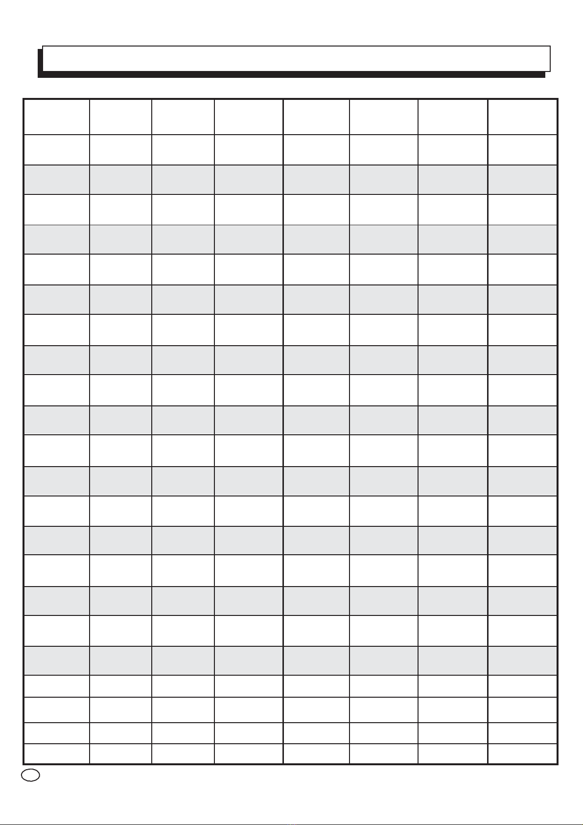
The ideal salt level is between 3200-4000 ppm. (parts per million) with 3600 ppm
being the optimal level. Calculate the number of gallons in the pool and add salt
according to the chart on page 8.
•
A LOW salt level will reduce the efficiency of the SPS and result in low chlorine
production.
•
Excessively HIGH salt levels will cause the SPS to shut down, making pool water
unsafe for bathers. LOW salt levels can cause the SPS to not operate efficiently,
causing the same.
TYPE OF SALT TO USE
•
It is important to use only sodium chloride (NaCl) that is 99% pure. This is common
food quality or water softener salt which is available in 40-80 lb/bag at your local pool
store. It is also acceptable to use water conditioning salt pellets; however it will take
longer for them to dissolve. DO NOT USE rock salt, salt with more than 1% yellow
prussiate of soda, salt with more than 1% of anti-caking additives, or iodized salt.
HOW TO ADD OR REMOVE SALT
•
ABOVE GROUND POOLS WITH MAIN DRAINS: Add directly in front of the return jet to
pool. Run the filter pump for 24 hours with the suction coming from the main drain
to allow the salt to evenly disperse throughout the pool.
•
ABOVE GROUND POOLS WITHOUT MAIN DRAINS: Add directly into the pool. Brush
the salt to speed up the dissolving process—to not allow the salt to sit in a pile on the
bottom of the pool (use the pool vacuum if there is no main drain) to allow the salt to
evenly disperse throughout the pool).
ON ANY POOL, DO NOT ADD SALT DIRECTLY TO THE SKIMMERS OR DIRECTLY
ONTO THE MAIN DRAIN. THIS WILL SHUT DOWN OR SHORTEN THE LIFE OF THE
CELL DUE TO HIGH SALT CONCENTRATION AND REDUCED FLOW TO THE PUMP.
If added incorrectly, immediately turn off SPS for 24 hours with the pump and filter
operating This will help to evenly distribute the salt. The salt display may take 24 hours
to respond to the change in salt concentration.
SALT DOES NOT EVAPORATE FROM POOL
•
The only way to lower the salt concentration is to partially drain the pool and refill
with fresh water.

8
POUNDS AND (Kg) OF SALT NEEDED FOR 3600 PPM
•
Gallons
and
(Liters)
of
Pool
water
CURRENT
6,000
8,000
10,000
12,000
14,000
16,000
18,000
SALT
LEVEL
PPM
(22,500) (30,000) (37,500) (45,000) (52,500) (60,000) (67,500)
0180
(82)
239
(109)
301
(136)
360
(163)
419
(190)
481
(218)
540
(245)
200
170
(78)
226
(103)
284
(129)
340
(154)
396
(180)
454
(206)
510
(232)
400 160
(73)
213
(97)
267
(121)
320
(145)
373
(170)
427
(194)
480
(218)
600
150
(69)
200
(91)
250
(114)
300
(136)
350
(159)
400
(182)
450
(205)
800 140
(64)
187
(85)
233
(106)
280
(127)
327
(148)
373
(170)
420
(191)
1000
130
(59)
173
(79)
217
(98)
260
(118)
303
(138)
347
(158)
390
(177)
1200 120
(55)
160
(73)
200
(91)
240
(109)
280
(127)
320
(145)
360
(164)
1400
110
(51)
147
(67)
183
(83)
220
(100)
257
(117)
293
(133)
330
(150)
1600 100
(46)
133
(61)
167
(76)
200
(91)
233
(106)
267
(121)
300
(136)
1800
90
(41)
120
(55)
150
(68)
180
(82)
210
(95)
240
(109)
270
(245)
2000 80
(36)
107
(48)
133
(61)
160
(73)
187
(85)
213
(97)
240
(109)
2200
70
(32)
93
(42)
117
(53)
140
(64)
163
(74)
187
(85)
210
(95)
2400
60
80
100
120
140
160
180
(27) (36) (45) (55) (64) (73) (82)
2600
50
67
83
100
117
133
150
(23)
(30)
(38)
(45)
(53)
(61)
(68)
2800
40
53
67
80
93
107
120
(18) (24) (30) (36) (42) (48) (55)
3000
30
40
50
60
70
80
90
(14) (18) (23) (27) (32) (36) (41)
3200 OK OK OK OK OK OK OK
3400 OK OK OK OK OK OK OK
3600 Ideal Ideal Ideal Ideal Ideal Ideal Ideal
3800 OK OK OK OK OK OK OK
4000 OK OK OK OK OK OK OK
4200+
Dilute Dilute Dilute Dilute Dilute Dilute Dilute

9
STABILIZER (CYANURIC ACID)
•
Always test for stabilizer (cyanuric acid) level, when testing for salt. This test should
be done at least once per month. Use the chart below to determine how much
stabilizer must be added to raise the level to 80 ppm .
POUNDS AND (Kg) OF STABILIZER (CYANURIC ACID)
NEEDED FOR 80 ppm
•
Gallons
and
(Liters)
of
Pool
water
CURRENT
6,000
8,000
10,000
12,000
14,000
16,000
18,000
STABILIZER
LEVEL
(ppm)
(22,500) (30,000) (37,500) (45,000) (52,500) (60,000) (67,500)
04.0
(1.8)
5.3
(2.4)
6.7
(3.0)
8.0
(3.6)
9.4
(4.3)
10.7
(4.9)
12.0
(5.4)
10 ppm 3.5
(1.6)
4.7
(2.1)
5.8
(2.6)
7.0
(3.2)
8.2
(3.7)
9.4
(4.3)
10.5
(4.8)
20 ppm 3.0
(1.4)
4.0
(1.8)
5.0
(2.3)
6.0
(2.7)
7.0
(3.2)
8.0
(3.6)
9.0
(2.2)
30 ppm 2.5
(1.1)
3.3
(1.5)
4.2
(1.9)
5.0
(2.3)
5.9
(2.7)
6.7
(3.0)
7.5
(3.4)
40 ppm 2.0
(.9)
2.7
(1.2)
3.3
(1.5)
4.0
(1.8)
4.7
(2.1)
5.4
(2.4)
6.0
(2.7)
50 ppm
1.5
(.7)
2.0
(.9)
2.5
(1.1)
3.0
(1.4)
3.5
(1.6)
4.0
(1.8)
4.5
(2.0)
60 ppm 1.0
(.5)
1.3
(.6)
1.7
(.8)
2.0
(.91)
2.4
(1.1)
2.7
(1.2)
3.0
(1.4)
70 ppm 0.5
(.2)
0.7
(.3)
0.8
(.4)
1.0
(.45)
1.2
(.54)
1.4
(.64)
1.5
(.68)
80 ppm 0.0 0.0 0.0 0.0 0.0 0.0 0.0
POLYMERS
•
It is advised to use polymers (commonly sold as poly algaecide) when using salt
water sanitizing systems. The poly algaecide is sold in 30% and 60% concentrations.
•
Application rate is 1 quart of Poly30 (or ½ quart of Poly 60) per 15,000 gallons
(60,000 liters) of pool water, per month. Apply directly in front of the return jet.

10
Min Max
CONTROLS
SPS aboveground Salt Generators have an Auto control system with a very simple
operation.
•
DESIRED LEVEL: There are 10 LEDS, each LED is 10%, chose the “desired
level %” by pressing Min to decrease or Max to increase. The SPS will produce
chlorine according to the “Desired Level %” adjustment setting for the entire
filter cycle.
•
MAX: Press Max to increase the level up to 100%, when you have an abnormally
high bather load, heavy rainfall, cloudy water conditions, or any other condition which
requires that a large amount of purification be introduced, Push Max until all
10 LEDS ARE ON. This electronically “Max chlorinates” (shocks) the water for 24
hours (filter pump must be on during this time) or until the power has been turned off,
whichever comes first. At the end of the Max chlorination period, be sure to push
Min to decrease level back to the desired level position.
•
MIN: Press Min to decrease the desired level. When all of the 10 LEDs are OFF,
it will prevent the SPS from energizing the electrolytic cell. In this position there is
no chlorine generation.
•
LOW SALT: When flashing, the salt level is low (below 2500 ppm) and SPS is
generating at low efficiency. When illuminated steady, the salt level is too low and
SPS has shut down.
NOTE:
In times of servicing, the OFF switch is not to be used.
To
service
the
SPS
,
turn
power
off
at
circuit
breaker.

11
INDICATOR LED
•
POWER:
When
LED
is
on
the
SPS
has
input
power.
•
NO FLOW: When illuminated, the flow switch has detected no flow and SPS is NOT
generating chlorine. A flashing LED indicates that the flow is restored, but there will
be a 60 second delay before generation is reestablished.
•
LOW SALT: When flashing, the salt level is low (below 2500 ppm) and SPS is
generating at low efficiency. When illuminated steady, the salt level is too low and
SPS has shut down.
•
Note: Before adding large quantities of salt, it is advisable to have your salt level
professionally checked.
•
Note: If the Salt level is at the correct level but the LOW SALT LEVEL is still on,
the cell has to be replaced.
•
HIGH SALT: When illuminated the salt level is around 4200 ppm. When illuminated
steady, salt level is higher than 4200 ppm and SPS has shut down. The pool water
must be diluted with fresh water before operation is restored.
OPERATION
By familiarizing yourself with the operation of the SPS generator, you can achieve
maximum performance for your pool. When chemical levels are in the recommended
range, there are FOUR factors that you can control which directly contribute to the
amount of chlorine the SPS will generate:
•
Filter
time
each
day
(hours)
•
The
amount
of
salt
in
the
pool
•
The
“
Desired
Level
%
”
setting
•
Stabilizer level in the water.
To find the optimum “Desired Level %” setting, start at a fairly high setting and work
downward. It will take a few days of adjustments to find the ideal setting for your pool.
Once determined, it should only take minor adjustments. The SPS control will not
produce chlorine at temperatures below 50°F. If your pool water is colder than 50°F,
you must chlorinate manually.
MAINTAINING THE SYSTEM
•
To maintain maximum performance, it is recommended that you remove and visually
inspect the cell every 3 months.
•
The SPS electrolytic cell has a self-cleaning feature incorporated into the electronic
control’s logic. In most cases this self-cleaning action will keep the cell working at
optimum efficiency. In areas where water is hard (high calcium and/or mineral content)
and in pools where the water chemistry has gotten “out of balance”, the cell may require
periodic cleaning every 3 months. After cleaning, if the LOW SALT is always ON even
with a good salt level, the cell may be worn and require replacement.

12
SERVICING AND CLEANING THE CELL
•
Turn
off
power
to
the
SPS
before
removing
the
CELL.
•
Once removed, look inside the cell and inspect for scale formation (light colored crusty or
flaky deposits) on the plates and for any debris that has passed through the filter and
gotten caught on the plates.
•
If no deposits are visible, reinstall. If deposits are seen, use a high-pressure garden hose
and try to flush the scale off. If this is not successful, use a plastic or wood tool to scrape
deposits off of the plates. DO NOT USE A METAL SCRAPER AS THIS WILL SCRATCH
THE FINISH AND DAMAGE THE PLATES. Note that a buildup on the cell indicates that
there is an unusually high calcium level in the pool (old pool water is usually the cause).
If this is not corrected, you will need to clean the cell more frequently. The simplest way to
avoid this is to bring the pool chemistry to recommended levels, as specified on page 5.
MILD ACID WASHING
Use only in severe cases where flushing and scraping will not remove the majority of
deposits. To acid wash:
•
Turn
off
power
to
SPS
.
•
Remove
cell
from
piping.
•
In a clean plastic container, carefully mix a 4:1 solution of water to muriatic acid
(one gallon of water to one quart of muriatic acid).
NOTE:
Always pour acid into water (Never pour water into acid)
Be sure to wear protective glasses, clothing and chemical resistant gloves
•
The level of the solution in the container should just reach the top of the cell so that the
wire harness compartment is NOT submerged. It may be helpful to coil the wiring before
immersing the cell.
•
The
cell
should
soak
for
FIVE
minutes,
then
rinse
with
a
high-pressure
garden
hose.
•
If
any
deposits
are
still
visible,
repeat
soaking
and
rinsing.
•
Replace
cell
and
inspect
again
periodically.
WINTERIZING
•
The SPS electrolytic cell and flow detection switch will be damaged by freezing water,
similar to other pool components that require proper winterization. In areas of the
country that experience severe or extended periods of freezing temperatures, be sure to
drain all water from the pump, filter, and supply and return lines before any freezing
conditions occur.
•
The electronic control is capable of withstanding any winter weather and should not be
removed.

MOUNTING THE SPS CONTROL

13
photo
SPRING START-UP
•
DO NOT turn SPS on, until the pool water chemistry has been balanced to proper levels.
INSTALLATION
•
The SPS electrolytic cell and flow detection switch will be damaged by freezing water,
similar to other pool components that require proper winterization. In areas of the country
that experience severe or extended periods of freezing temperatures, be sure to drain
all water from the pump, filter, and supply and return lines before any freezing conditions
occur.
•
The electronic control is capable of withstanding any winter weather and should not be
removed.
•
The SPS control panel must be mounted a minimum of 5 ft. (2 meters) horizontal
distance (or more if local codes require) from the pool.
•
The control is designed to mount vertically on a flat surface with the knockouts facing
downward and not to block the four sides of the control.
•
Do not mount the SPS in a panel or tightly enclosed space.
PLUMBING
SKIMMER
120
VAC
GFCI
OUTLET
PUMP
SPS SALT
FILTER
RETURN
FLOW
SWITCH
CELL
•
The cell and flow switch are plumbed
in the return line to the pool. Install
after all the pool equipment (filter,
heater, solar, etc.). The kit included
in the SPS provides the necessary
plumbing components for either
1½” (38 mm) rigid PVC piping glue
installation or 1½” (38mm) threaded
installation.
GENERATOR

14
HOSE PIPE INSTALLATIONS (-HP Option)
•
Install the cell and flow switch as shown in the diagrams below. Always make sure that
the flow switch is after the cell. When using the hose adaptors, remove the O-ring from
the pipe union tailpiece and install them in the hose tailpieces. Tighten all union nuts
BY HAND for a watertight seal.
HOSE ASSEMBLY
FROM PUMP TO POOL
PIPE ASSEMBLY
FROM PUMP TO POOL
WIRING
•
Power must be turned off before performing any wiring. Be sure to follow Local and NEC
electrical codes. To provide safe operation, SPS must be properly grounded and bonded.
INPUT POWER
•
Wire the SPS to the LOAD SIDE of the filter pump timer. It is very important that the
SPS is powered only when the pump is running.
ELECTROLYTIC CELL AND FLOW SWITCH
•
The electrolytic cell and flow switch cables are terminated with connectors that plug into
the SPS for easy attachment and removal. The flow switch plugs into a connector
(similar to a telephone jack) located outside, on the bottom of the enclosure.

15
TROUBLESHOOTING
1
“
Power
”
LED
not
on
Check to make sure 120V AC input power is connected to the control. Verify input voltage
with a voltmeter. If there is input power, the fuse may have blown. The board is
protected by a 5 amp mini ATO fuse located on the circuit board above the cell connector.
2
“No Flow” LED illuminated or flashing
The
SPS
has
sensed
a
no
flow
condition
and
has
stopped
generating
chlorine.
Check
that
the
flow
switch
is
plugged
into
the
connector
on
the
bottom
of
the
control
unit
and
that
the
wire
is
not
cut
or
damaged.
Make
sure
you
have
at
least
12
”
of
straight
pipe
before
the
flow
switch.
If
there
is
adequate
flow
and
the
LED
is
still
on,
check
that
the
arrows
on
the
flow
switch
are
pointing
in
the
direction
of
flow.
3
L
OW
SALT
LED
illuminated
or
flashing
Check
salt
level
in
pool.
If
salt
level
is
low,
add
salt
according
to
chart
on
page
8.
Before
adding
large
quantities
of
salt,
it
is
advisable
to
have
your
salt
level
professionally
checked.
NOTE: If salt level is correct after the cleaning of the cell but the LOW SALT LED still ON,
the cell may be worn and needs replacement.
4
High
Salt
LED
illuminated
or
flashing
Check
salt
level
in
pool.
If
salt
level
is
too
high,
lower
salt
level
by
draining
some
of
the
pool
water
out
of
the
pool
and
replace
with
fresh
water.
Continue
until
the
salt
concentration
is
at
recommended
levels.
5
Replace
the
new
cell
Remove
and
inspect
the
cell
for
scale.
If
the
cell
is
scaled,
follow
the
directions
on
page
12
for
cell
cleaning.
If
the
pool
has
the
proper
amount
of
salt
and
the
LOW
SALT
LED
is
still
illuminated,
the
cell
may
be
depleted
and
needs
to
be
replaced.
6Possible causes of low chlorine or no chlorine
•
SPS
switch
in
OFF
position.
•
Desired
Level%
adjustment
setting
is
too
low.
•
Low stabilizer (Cyanuric Acid).Chlorine is being produced but the pool water is unable to
hold
on
to
the
chlorine,
due
to
low
stabilizer.
•
Filter pump switched off or filter pump time too short (8 hours for average size pools,
more
for
large
pools).
•
Salt
level
too
low
(below
2500
ppm,
Low
Salt
LED
on).
•
Salt
level
too
high
(high
Salt
LED
on).
•
Low pH. Low pH oxidizes chlorine quickly, making it difficult to maintain desired chlorine
levels.
Adjust
pH
levels
to
re-balance
water.
•
Warm
pool
water
increases
chlorine
demand
—
increase
Desired
Level%
or
filter
run
time.
•
Cold
water
(below
50F)
can
cause
SPS
to
stop
generating
•
Excessive
scaling
on
cell.
•
High
level
of
phosphates
in
pool
water.
•
Some
yellow
algae
treatments
will
use
chlorine
at
a
very
high
rate
and
deplete
the
residual
free
chlorine.
Manually
shock
the
pool
if
indicated
in
the
directions
on
the
algae
treatment.
It
still
may
be
a
matter
of
days
before
the
pool
returns
to
“
normal
”
and
chlorine
tests
will
show
the
desired
1-3ppm
free
chlorine
reading.
Table of contents
Popular Lighting Equipment manuals by other brands

Claypaky
Claypaky Mini-B WW instruction manual

afx light
afx light SPARK-FIREWORKS user manual

Dynalite
Dynalite RR-GH instruction manual

Dop Choice
Dop Choice SNAPGRID operating instructions

Lightmybricks
Lightmybricks LEGO Ninjago City 70620 Lighting Kit instructions

Astral Pool
Astral Pool Selwatch installation & utilisation notice