Fujitsu Frenic Eco FRN-F1 How to use

Fuji Electric GmbH .Goethering 58 .63067 Offenbach/Main .Germany
STARTING GUIDE
FRENIC Eco .FRN-F1
Fuji Electric frequency inverter
for HVAC applications
3-phase 400V
0.75 –500kW

I
FRN
-
F1
CONTENT
Chapter Page
1. SAFETY INFORMATION AND CONFORMITY TO STANDARDS……………………………………………... 1
1.1 Safety Information…………………………………………………………………………………………………… 1
1.2 Conformity to Standards…………………………………………………………………………………………….. 3
1.2.1 Conformity to European Standards………………………………………………………………………………... 3
1.2.2 Conformity to Low Voltage Directive………………………………………………………………………………. 3
2. MECHANICAL INSTALLATION…………………………………………………………………………………….. 4
2.1 Installing the Inverter………………………………………………………………………………………………… 4
2.2 Mounting direction…………………………………………………………………………………………………… 4
2.3 Removing and Mounting the Terminal Block cover and the Front Cover……………………………………… 4
3. ELECTRICAL INSTALLATION……………………………………………………………………………………... 6
3.1 Power Terminals……………………………………………………………………………………………………... 6
3.2 Control Terminals…………………………………………………………………………………………………….. 7
3.2.1 Control Terminals Connection……………………………………………………………………………………… 8
4. OPERATION USING THE KEYPAD……………………………………………………………………………….. 9
5. QUICK STARTING COMMISSIONING……………………………………………………………………………. 10
5.1 Running the Motor for a Test……………………………………………………………………………………….. 10
5.1.1 Inspection and preparation prior to powering on…………………………………………………………………. 10
5.1.2 Turning on power and checking……………………………………………………………………………………. 10
5.1.3 Preparation before running the motor for a test--Setting function code data…………………………………. 10
5.1.4 Procedure for Test Run……………………………………………………………………………………………… 11
5.2 Operation………………………………………………………………………………………………………………
11
6. FUNCTION CODES…………………………………………………………………………………………………. 12
6.1 Function Codes Tables……………………………………………………………………………………………… 12
6.2 Overview of Function Codes……………………………………………………………………………………….. 14
7. PROTECTIVE FUNCTIONS………………………………………………………………………………………... 22
7.1 Protection / Maintenance Function (Parameter H98)……………………………………………………………. 22
7.2 Dew Condensation Protection (Parameter J21)………………………………………………………………….. 23
8. SPECIFICATIONS AND EXTERNAL DIMENSIONS…………………………………………………………….. 24
8.1 Inverter Specifications………………………………………………………………………………………………. 24
8.1.1 Standard Model –IP20 / IP00……………………………………………………………………………………… 24
8.1.2 Semi standard –IP54 with integral EMC filter and DCR………………………………………………………… 26

II
FRN
-
F1
8.2 External Dimensions………………………………………………………………………………………………… 27
8.2.1 Inverter Standard Models.............................................................................................................................. 27
8.2.2 Inverter IP54 Models..................................................................................................................................... 28
8.3 Keypad Dimensions..................................................................................................................................... 29
9. OPTIONS………………………………………………………………………………………………………………
30
Preface
Thank you for purchasing our FRENIC-Eco series of inverters.
This product is designed to drive a three-phase induction motor for fan and pump applications.
Read through this starting guide and become familiar with proper handling and operation of this product. Please note that this
starting guide should enable you to get familiar with the main functions and should help you to install the inverter. Not all functions
are described here. For more detailed information please refer absolutely to the attached CD-ROM which contains the user manual
(MEH456).
Improper handling might result in incorrect operation, a short life, or even a failure of this product as well as the motor.
Have this manual delivered to the end user of this product. Keep this starting guide and CD-ROM in a safe place until this product is
discarded.
Listed below are the other materials related to the use of the FRENIC-Eco. Read them in conjunction with this starting guide as
necessary.
•FRENIC-Eco User's Manual (MEH456)
•RS485 Communication User's Manual (MEH448)
•Catalogue (MEH442)
•RS485 Communications Card "OPC-F1-RS" Installation Manual (INR-SI47-0872)
•Relay Output Card "OPC-F1-RY" Instruction Manual (INR-SI47-0873)
•Mounting Adapter for External Cooling "PB-F1" Installation Manual (INR-SI47-0880)
•Panel-mount Adapter "MA-F1" Installation Manual (INR-SI47-0881)
•Multi-function Keypad "TP-G1" Instruction Manual (INR-SI47-0890-E)
•FRENIC Loader Instruction Manual (INR-SI47-0903-E)
The materials are subject to change without notice. Be sure to obtain the latest editions for use.

Chapter 1: Safety Information and Conformity to Standards
1
FRN
-
F1
1. SAFETY INFORMATION AND CONFORMITY TO STANDARDS
1.1 Safety Information
Read this manual thoroughly before proceeding with installation, connections(wiring), operation, or maintenance and inspection.
Ensure you have sound knowledge of the device and familiarize yourself with all safety information and precautions before
proceeding to operate the inverter.
Safety precautions are classified into the following two categories in this manual.
Application
•FRENIC-Eco is designed to drive a three-phase induction motor. Do not use it for single-phase motors or for other purposes. Fire or an accident
could occur.
•FRENIC-Eco may not be used for a life-support system or other purposes directly related to the human safety.
•Though FRENIC-Eco is manufactured under strict quality control, install safety devices for applications where serious accidents or material losses
are foreseen in relation to the failure of it. An accident could occur.
Installation
•Install the inverter on a nonflammable material such as metal. Otherwise fire could occur.
•Do not place flammable matter nearby. Doing so could cause fire.
•Do not support the inverter by its terminal block cover during transportation. Doing so could cause a drop of the inverter and injuries.
•Prevent lint, paper fibers, sawdust, dust, metallic chips,or other foreign materials from getting into the inverter or from accumulating on the heat
sink. Otherwise, a fire or an accident might result.
•Do not install or operate an inverter that is damaged or lacking parts. Doing so could cause fire, an accident or injuries.
•Do not get on a shipping box.
•Do not stack shipping boxes higher than the indicated information printed on those boxes. Doing so could cause injuries.
Maintenance and inspection,and parts replacement
•Turn the power OFF and wait for at least five minutes for models of 30 kW or below, or ten minutes for models of 37 kW or above,before starting
inspection. Further, check that the LED monitor is unlit, and check the DC link bus voltage between the P (+) and N (-) terminals to be lower than
25 VDC. Otherwise,electric shock could occur.
•Maintenance, inspection,and parts replacement should be made only by qualified persons.
•Take off the watch, rings and other metallic matter before starting work.
•Use insulated tools. Otherwise,electric shock or injuries could occur.
Disposal
•Handle the inverter as an industrial waste when disposing of it. Otherwise injuries could occur.
Others
•Never attempt to modify the inverter. Doing so could cause electric shock or injuries.
Wiring
•When wiring the inverter to the power source, insert a recommended molded case circuit breaker (MCCB) or residual-current-operated protective
device (RCD)/earth leakage circuit breaker (ELCB) (with overcurrent protection) in the path of power lines.Use the devices within the
recommended current range.

Chapter 1: Safety Information and Conformity to Standards
2
FRN
-
F1
•Use wires in the specified size. Otherwise, fire could occur.
•Do not use one multicore cable in order to connect several inverters with motors.
•Do not connect a surge killer to the inverter's output (secondary) circuit. Doing so could cause fire.
•Ground the inverter following Class C or Class D specifications or national/local electric code, depending on the input (primary) voltage of the
inverter. Otherwise, electric shock could occur.
•Qualified electricians should carry out wiring.
•Be sure to perform wiring after turning the power OFF.Otherwise,electric shock could occur.
•Be sure to perform wiring after installing the inverter body. Otherwise,electric shock or injuries could occur.
•Ensure that the number of input phases and the rated voltage of the product match the number of phases and the voltage of the AC power supply
to which the product is to be connected. Otherwise fire or an accident could occur.
•Do not connect the power source wires to output terminals (U, V, and W). Doing so could cause fire or an accident.
•Generally, control signal wires are not enforced-insulated. If they accidentally touch any of hot power lines, their insulation coat may break for any
reasons. In such a case, an extremely high voltage may be applied to the signal lines. Make a complete remedy to protect the signal line from
contacting any hot high voltage lines. Otherwise,an accident or electric shock could occur.
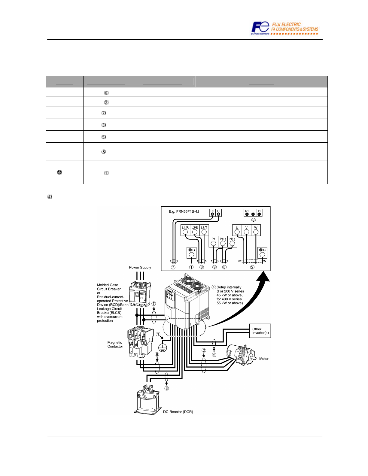
•Wire the three-phase motor to terminals U, V, and Wof the inverter, aligning phases each other. Otherwise injuries could occur.
•The inverter, motor and wiring generate electric noise. Take care of malfunction of the nearby sensors and devices. To prevent the motor from
malfunctioning, implement noise control measures. Otherwise an accident could occur.
Setting control switches
•Before setting up any internal control switches, turn OFF the power, wait more than five minutes for models of 30 kW or below, or ten minutes for
models of 37 kW or above, and make sure, using a multimeter or a similar instrument, that the DC link bus voltage between the terminals P (+)
and N (-) has dropped below a safe voltage (+25 VDC).Otherwise electric shock could occur.
Operation
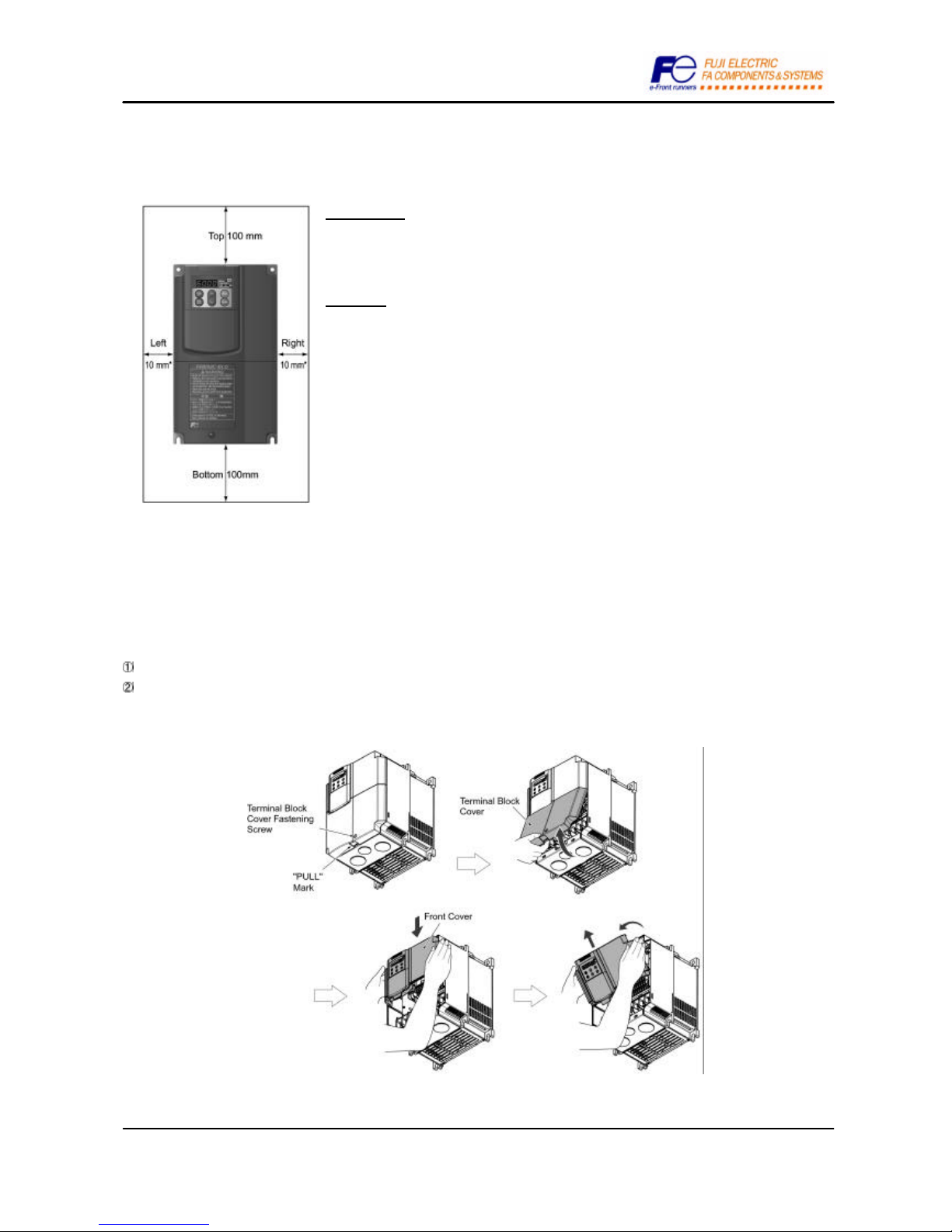
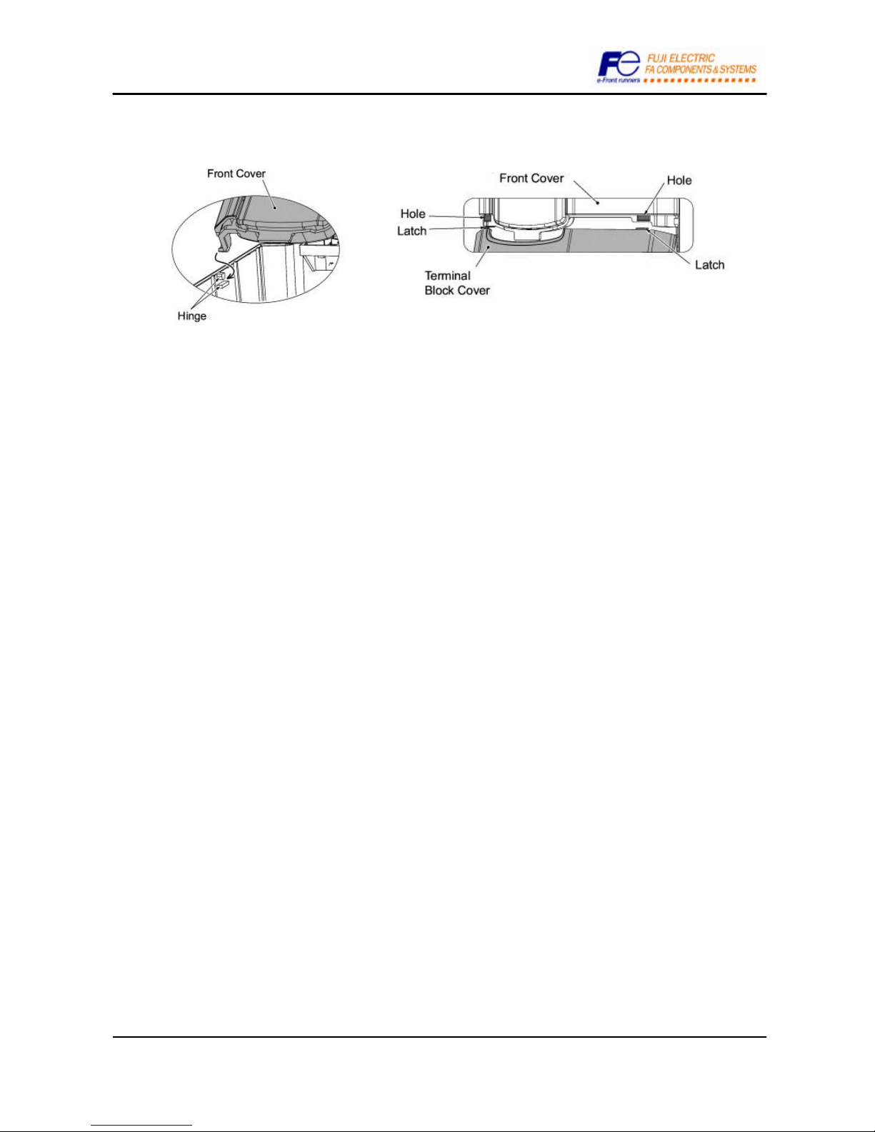
•Be sure to install the terminal block cover and the front cover before turning the power ON. Do not remove the coverswhile power is applied.
Otherwise electric shock could occur.
•Do not operate switches with wet hands. Doing so could cause electric shock.
•If the retry function has been selected, the inverter may automatically restart and drive the motor depending on the cause of tripping.
(Design the machinery or equipment so that human safety is ensured after restarting.)
•If the stall prevention function (current limiter), automatic deceleration, and overload prevention control have been selected, the inverter may
operate at an acceleration/deceleration time or frequency different from the commanded ones. Design the machine so that safety is ensured even
in such cases. Otherwise an accident could occur.
•The STOP key is only effective when function setting (Function code F02) has been established to enable the STOP key. Prepare an emergency
stop switch separately. If you disable the STOP key priority function and enable operation by external commands, you cannot emergency-stop the
inverter using the STOP key on the built-in keypad.
•If an alarm reset is made with the Run command signal turned ON, a sudden start will occur. Ensure that the Run command signal is turned OFF
in advance. Otherwise an accident could occur.
•If you enable the "restart mode after instantaneous power failure"(Function code F14 = 3, 4, or 5), then the inverter automatically restarts running
the motor when the power is recovered. (Design the machinery or equipment so that human safety is ensured after restarting.)
•If you set the function codes wrongly or without completely understanding this instruction manual and the FRENIC-Eco User's Manual (MEH456),
the motor may rotate with a torque or at a speed not permitted for the machine. An accident or injuries could occur.
•Do not touch the inverter terminals while the power is applied to the inverter even if the inverter stops. Doing so could cause electric shock.
•Do not turn the main circuit power (circuit breaker) ON or OFF in order to start or stop inverter operation. Doing so could cause failure.
•Do not touch the heat sink because they become very hot. Doing so could cause burns.
•Setting the inverter to high speeds is easy. Before changing the frequency (speed) setting, check the specifications of the motor and machinery.
•The brake function of the inverter does not provide mechanical holding means. Injuries could occur.
GENERAL PRECAUTIONS
Drawings in this manual may be illustrated without covers or safety shields for explanation of detail parts. Restore the covers and shields in the
original state and observe the description in the manual before starting operation.

Chapter 1: Safety Information and Conformity to Standards
3
FRN
-
F1
1.2 Conformity to Standards
1.2.1 .Conformity to European Standards
The CE Approved on Fuji products indicates that they comply with the essential requirements of the Electromagnetic Compatibility
(EMC) Directive 89/336/EEC issued by the Council of the European Communities and the Low Voltage Directive 73/23/EEC.
Only the models with a built-in EMC-compliant filter that bear a CE Approved are compliant with the EMC Directive.
Inverters that bear a CE Approved are compliant with the Low Voltage Directive.
¦The FRENIC-Eco series of inverters with conformity to the following standards:
Low Voltage Directive EN50178:1997
EMC Directives EN61800-3:1996 + A11: 2000 EN55011: 1998 + A1:1999
CAUTION
The FRENIC-Eco series of inverters are categorized as a "restricted sales distribution class" provided in the EN61800-3. When you
use these products with any home appliance or office equipment, you may need to take appropriate countermeasures to reduce or
eliminate any noise emitted from these products.
1.2.2 Conformity to Low Voltage Directive
General-purpose inverters are subject to the regulations set forth by the Low Voltage Directive in Europe. Fuji has obtained a
certification of compliance from a European test organization for its FRENIC-Eco series inverters and labels them with a CE
Approved, which is a self-declaration with conformity to the Low Voltage Directive.
Considerations when using FRENIC-Eco as a product with conformity to Low Voltage Directive
If you wish to use a FRENIC-Eco series inverter as a product with conformity to the Low Voltage Directive, refer to the related
guidelines.

Chapter 2: Mechanical Installation
4
FRN
-
F1
2. Mechanical Installation
2.1 Installing the Inverter
Mounting base
The inverter should be mounted on a base made of material that can withstand heat sink
temperature, which can rise up to 90ºC approx. during inverter operation.
Clearances
Ensure that the minimum clearances indicated are maintained at all times. When installing the
inverter in the enclosure of your system, take extra care with ventilation inside the enclosure
as the temperature around the inverter will tend to increase. Do not install the inverter in a
small enclosure with poor ventilation.
*For 37Kw or above a 50 mm clearance is needed instead of 10 mm (left and right sides).
As long as the ambient temperature is 40°C or lower, 5.5 kW or lower inverters may be
mounted side-by-side without any gap between them.
For others inverters, please follow the clearances needed.
2.2 Mounting Direction
Horizontal layout is recommended when two or more inverters are to be installed in an equipment or enclosure. If it is necessary to
mount the inverters vertically, install a partition plate or the like between the inverters so that any heat radiating from an inverter will
not affect the one/s above.
2.3 Removing and Mounting the Terminal Block (TB) Cover and the Front Cover
To remove the TB cover, loosen the fastening screw on it, hold the dimple (labelled “PULL”), and pull it up towards you.
To remove the front cover, hold it with both hands, slide it downward, disengage the latch at the top from the inverter, tilt the front
cover toward you, and pull it upward.

Chapter 2: Mechanical Installation
5
FRN
-
F1
For inverters with a capacity of 30 kW or below (for others please refer to user's manual chapter 2).
For mounting the covers, please refer to next snapshots and follow removing instructions in the opposite way.

Chapter 3: Electrical Installation
6
FRN
-
F1
3. Electrical Installation
3.1. Power Terminals *Perform wiring as necessary
Symbol Wiring procedure Terminal function Description
L1/R, L2/S, L3/T Main power inputs Connect the 3-phase input power lines.
U, V, W Inverter outputs Connect a 3-phase motor
R0, T0 * Auxiliary power input for the
control circuit
For a backup of the control circuit power supply, connect AC power
lines same as that of the main power input.
P1, P(+) * DC reactor connection Connect a DC reactor (DCR) for improving power factor (an option
for the inverter whose capacity is 55 kW or below).
P(+), N(-) * DC link bus Connect a DC link bus of other inverter(s). An optional regenerative
converter is also connectable to these terminals.
R1, T1 *
Auxiliary power input for the fans
(Refer to chapter 8.4.1 of user's
manual)
Normally, no need to use these terminals. Use these terminals for an
auxiliary power input of the fans in a power system using a power
regenerative PWM converter (RHC series).
Gx 2 Grounding for inverter and motor
Grounding terminals for the inverter’s chassis (or case) and motor.
Earth one of the terminals and connect the grounding terminal of the
motor. Inverters provide a pair of grounding terminals that function
equivalently.
Switching connectors (for models 400 V series 55 kW or above. Refer to chapter 8.4.1 of user's manual.)

Chapter 3: Electrical Installation
7
FRN
-
F1
3.2. Control Terminals
The FRENIC ECO inverter has 7 digital inputs (two fixed and five programmable), 3 programmable transistor outputs and 2 relay
outputs (one fixed and one programmable).
Symbols
Type Programmable
Example of use Description
PLC Connects to PLC output
signal power supply -- --
To turn ON or OFF digital inputs using a
relay or a PLC.
24VDC max. current 50mA
CM Digital common -- -- Two common terminals for digital input
signal terminals
FWD Run forward command YES -- External run command UP
REV Run reverse command YES -- External run command DOWN
X1-X5 Digital inputs YES
Speed selection
Coast to stop
etc.
Programmable digital inputs
Program the required function in
parameters E01 through E05
Y5 A/C General purpose relay
output YES MC control signal
Inverter ready
30 A,B,C
Alarm relay output YES Signal to control system that the
inverter has an alarm
Programmable relay contact output.
Program the required function in
parameters E24 / E27
Y1-Y3 Transistor outputs YES Same as relay output Y5 / 30A
Programmable transistor outputs.
Program the required function in
parameters E20 through E22
CMY Transistor output common -- -- Common terminal for transistor output
signal terminals
Electrical specification for digital inputs (X1 to X5):Electrical specification for transistor outputs:
Item Min. Max.
ON level 0 V 2V
Operation
voltage
(SINK)OFF level 22 V 27V
ON level 22 V 27V
Operation
voltage
(SOURCE)
OFF level 0 V 2V
Operation current at ON
(Input voltage is at 0V) 2.5 mA 5 mA
Allowable leakage current at OFF
-0.5 mA
Item Max.
ON level 3 V
Operation
voltage OFF level 27 V
Maximum load current at ON 50 mA
Leakage current at OFF 0.1 mA
Electrical specification for relay contact outputs:48 VDC, 0.5 A

Chapter 3: Electrical Installation
8
FRN
-
F1
3.2.1 Control Terminals Connection
Digital inputs and outputs can be operated both in NPN (sink) and PNP (source) logic.
a) DIGITAL INPUTS: Refer to the user's manual MEH456 for connection examples.
SW1 SINK SW1 SOURCE
The switch SW1 located on the control board defines the logic
used for digital inputs. Factory default setting is source.
? SINK LOGIC: Digital input ON giving 0 volts.
? SOURCE LOGIC: Digital input ON giving 24 volts.
b) TRANSISTOR OUTPUTS: Refer to the user's manual MEH456 for connection examples.
To decide what logic to use, there is no switch as before.
Connecting “PLC” terminal to the transistor common “CMY” terminal you will have PNP logic.
Connecting “CM” terminal to the transistor common “CMY” terminal you will have NPN logic.
c) RELAY OUTPUTS:
Y5A/C RELAY: you can switch its output mode between “Active ON”
(the terminals [Y5A] and [Y5C] are short-circuited if the signal is
active) and “Active OFF” (the terminals [Y5A] and [Y5C] are open-
circuited if the signal is active).
30A/B/C RELAY:switching of the normal/negative logic output is
applicable to the following two contact outputs: "Terminals [30A] and
[30C] are short-circuited for ON signal output (Active ON)" or "the
terminals [30B] and [30C] are short-circuited (non-excite) for ON
signal output (Active OFF)."
Y5A
30A
30B
Y5C
30C

Chapter 4: Keys and LED on the Keypad
9
FRN
-
F1
4. OPERATION USING THE KEYPAD
As shown in the figure at right, the keypad
consists of a four-digit LED monitor, 5 LED
indicators, and six keys.
The keypad allows you to start and stop the
motor, monitor running status, and switch to the
menu mode. In the menu mode, you may set
the function code data, monitor I/O signal
states, maintenance information, and alarm
information.
Item Monitor,
LED indicators
and Keys Functions
LED
Monitor
Four-digit, 7-segment LED monitor which displays the following according to the operation modes.
nIn Running Mode: Running status information (e.g., output frequency, current, and voltage)
nIn Programming Mode: Menus, function codes and their data
nIn Alarm Mode: Alarm code, which identifies the error factor if the protective function is
activated.
Program/Reset key which switches the operation modes of the inverter.
nIn Running Mode: Pressing this key switches the inverter to Programming Mode.
nIn Programming Mode: Pressing this key switches the inverter to Running Mode.
nIn Alarm Mode: Pressing this key after removing the error factor will switch the inverter
to Running Mode.
Function/Data key which switches the operation you want to do in each mode as follows:
nIn Running Mode: Pressing this key switch the information to be displayed concerning the
status of the inverter (output frequency (Hz), output current (A), output
voltage (V), etc.).
nIn Programming Mode: Pressing this key displays the function code and sets the data entered
with and keys.
nIn Alarm Mode: Pressing this key displays the details of the problem indicated by the
alarm code that has come up on the LED monitor.
RUN key. Press this key to run the motor.
STOP key. Press this key to stop the motor.
Operation
Keys
and UP and DOWN keys. Press these keys to select the setting items and change the function data
displayed on the LED monitor.
RUN LED Lights when any run command to the inverter is active, In Programming and Alarm modes, you
cannot run the inverter even if the indicator lights.
KEYPAD
CONTROL LED Lights when the inverter is running by the run command from the key.
The lower 3 LED indicators identify the unit of numeral displayed on the LED monitor in Running
Mode by combination of lit and unlit states of them in the category shown below.
kW, A, Hz, r/min and m/min
LED
Indicators
Unit and Mode expression
by the three LED
indicators
While the inverter is in Programming Mode, the LEDs at both ends of the lower indicators light.
In Programming Mode: ¦Hz ?A ¦kW
STOP key
LED
indicators
RUN key
LED monitor
Down key
Up key
Function/
Data key
Program/
Reset key

Chapter 5: Quick Starting Commissioning
10
FRN
-
F1
5. QUICK STARTING COMMISSIONING
5.1 Running the Motor for a Test
5.1.1 Inspection and preparation prior to powering on
Check the following prior to starting powering on.
(1) Check if connection is correct.
Especially check if the power wires are connected to the inverter input terminals L1/R, L2/S and L3/T, and output
terminals U, V and W respectively and that the grounding wires are connected to the ground electrodes correctly. Note
that FRENIC-Eco series inverter is designed for three phase input and driving three phase motors.
•Do not connect power supply wires to the inverter output terminals U, V, and W. Otherwise, the inverter may
be broken if you turn the power on.
•Be sure to connect the grounding wires of the inverter and the motor to the ground electrodes.
Otherwise, electric shock may occur.
(2) Check for short circuits between terminals and exposed live
parts and ground faults.
(3) Check for loose terminals, connectors and screws.
(4) Check if the motor is separated from mechanical equipment.
(5) Turn the switches off so that the inverter does not start or
operate erroneously at power-on.
(6) Check if safety measures are taken against runaway of the
system, e.g., a defense to protect people from unexpectedly
approaching your power system.
Figure 5.1 Connection of Main Circuit Terminals
5.1.2 Turning on power and checking
Turn the power on and check the following points. This is
a case when no function code data is changed from the
factory setting.
(1) Check if the LED monitor displays "*00 " (means that the
frequency command is 0 Hz) that is blinking. (See Figure
5.2.)
If the LED monitor displays numbers except "*00 " then
press the / key to set "*00 " as the frequency
command.
(2) Check if a built-in cooling fan rotates.
Figure 5.2 Display of the LED Monitor after Power-on
5.1.3 Preparation before running the motor for a test--Setting function code data
Before starting running the motor, set function code data specified in Table 5.1 to the motor ratings and your system
design values. For the motor, check the rated values printed on the nameplate of the motor. For your system design
values, ask system designers about them.
&For details about how to change function code data, refer to Chapter 4. Refer to the function code H03 in Chapter 6
"FUNCTION CODES" for the factory default setting of motor parameters. If any of them is different from the default setting,
change the function code data.

Chapter 5: Quick Starting Commissioning
11
FRN
-
F1
Table 5.1 Settings of Function Code Data before Driving the Motor for a Test
Function
code
Name Function code data Factory setting
F 04 Base frequency 50.0 (Hz)
F 05 Rated voltage (at base
frequency)
Motor ratings (printed on the
nameplate of the motor) 0 (V) (Output voltage interlocked with the input voltage)
F 03 Maximum frequency 50.0 (Hz)
F 07 Acceleration time 1* 20.0 (sec)
F 08 Deceleration time 1*
System design values
* For a test-driving of the motor,
increase values so that they are
longer than your system design
values. If the set time is short, the
inverter may not start running the
motor.
20.0 (sec)
P 02 Motor parameter (Rated capacity)
Applicable motor rated capacity
P 03 Motor parameter (Rated current) Rated current of applicable motor
P 99 Motor Selection
Motor ratings (printed on the
nameplate of the motor) 0: Characteristic of ICE motor.
5.1.4 Procedure for Test Run
(1) Turn the power on and check that the LED monitor blinks while indicating the *00 Hz frequency.
(2) Set the frequency to a low frequency such as 5 Hz, using the / key. (Check that frequency command blinks on
the LED monitor.)
(3) Press the key to start running the motor in the forward direction. (Check that the frequency command is displayed
on the LED monitor correctly.)
(4) To stop the motor, press the key.
<Check the following points>
•Check if the direction of rotation is forward.
•Check for smooth rotation without motor humming or excessive vibration.
•Check for smooth acceleration and deceleration.
When no abnormality is found, press the key again to start driving the motor, and increase the frequency command
using the / key. Check the above points for the test-driving of the motor.
----------------------------------------------------------------------------------------------------------------------------------------------------
5.2 Operation
After confirming normal operation by performing a test run, make mechanical connections (connections of the machine
system) and electrical connections (wiring and cabling), and set the necessary parameters properly before starting a
production run.
Depending on the conditions of
the production run, further adjustments can be required, such as adjustments of torque
boost (F09), acceleration time (F07), and deceleration time (F08). Make sure to set relevant function codes properly.

Chapter 6: Function Codes
12
FRN
-
F1
6. FUNCTION CODES
6.1 Function Codes Tables
Function codes enable the FRENIC-Eco series of inverters to be set up to match your system requirements.
Each function code consists of a 3-letter string. The first letter is an alphabet that identifies its group and the following two letters
are numerals that identify each individual code in the group. The function codes are classified into eight groups: Fundamental
Functions (F codes), Extension Terminal Functions (E codes), Control Functions of Frequency (C codes), Motor Parameters (P
codes), High Performance Functions (H codes), Application Functions (J codes),Link Function (y codes) and. Option Function (o
codes) To determine the property of each function code, set data to the function code.
For Option function (o codes), refer to the instruction manual for the option.
nUsing negative logic for programmable I/O terminals
The negative logic signaling system can be used for the digital input and output terminals by setting the function codes specifying
the properties for those terminals. Negative logic refers to inverted ON/OFF (logical value 1 (true)/0 (false)) state of input or
output signal. An ON-active signal (the function takes effect if the terminal is short-circuited.) in the normal logic system is
functionally equivalent to OFF-active signal (the function takes effect if the terminal is opened.) in the negative logic system.
To set the negative logic system for an I/O signal terminal, display data of 1000s (by adding 1000 to the data for the normal logic)
in the corresponding function code and then press the key.
For example, if a coast-to-stop command (BX: data = 7) is assigned to any one of digital input terminals [X1] to [X3] by setting
any of function codes E01 through E03, then turning (BX) on will make the motor coast to a stop. Similarly, if the coast-to-stop
command (BX: data = 1007) is assigned, turning (BX) off will make the motor coast to a stop.
The following tables list the function codes available for the FRENIC-Eco series of inverters.
&If you find any [-] (not available here) mark in the related page column of the function code tables, refer to FRENIC-Eco
User’s Manual (MEH456) for details.
F codes: Fundamental functions
Code Name Setting Range Factory default See
Page:
F00 Data Protection 0 / 1 0
F01 Frequency command 1 0 ~ 3 / 5 / 7 014
F02 Operation method 0 ~ 4 015
F03 Maximum frequency1 25 ~ 120Hz 50Hz 16
F04 Base frequency 1 25 ~ 120Hz 50Hz 16
F05 Rated voltage 1 0 / 160 ~ 500V 400V 16
F07 Acceleration time 1 0.00 ~ 3600s 20s 16
F08 Deceleration time 1 0.00 ~ 3600s 20s 16
F09 Torque boost 1 0.0 ~ 20.0 Depending on the rated capacity
17
F10 Function
1 / 2 117
F11 Level
0.0 (Disable)
1 ~ 135% INMot.
Nominal rated current (100%) of
the motor 17
F12
Electric thermal overload relay 1
Time
0.5 ~ 75min 5.0 (22kW or
below)
10.0 (30kW or
below 17
F14 Restart after moment. power failure 0 ~ 5 118
F15 high
0~120Hz 70.0Hz
F16 Frequency limiter low
0~120Hz 0.0Hz 19
F18 Bias Frequency 1 -100.00~+100.00 % 0.00%
F20 Frequency
0.0~60.0Hz 0.0Hz
F21 Level
0 ~ 100% 0%
F22
DC Brake
Time
0 / 0.01 ~ 30.0s 0.00s
F23 Starting frequency 0.1 ~ 60.0Hz 0.5Hz
F25 Stopping frequency 0.1 ~ 60.0Hz 0.2Hz
0.75~15 kHz
(22kW or below) 15kHz 19
0.75~10 kHz
(30kW to 75kW) 10kHz 19
F26
Motor Sound
Carrier
frequency
0.75~6 kHz
(90kW or above) 6kHz 19

Chapter 6: Function Codes
13
FRN
-
F1
F27 Tone
0~3 0
F29 Selection
0 / 1 0
F30 Level
0~200% 100%
F31
Analog Output (FMA)
Function
0 ~ 16 0
F33 Pulsrate
25 ~ 6000p/s 1440p/s
F34 Level
0% / 1 ~ 200% 0%
F35
FMP Terminal
Function
0 ~ 16 0
F37 Load selection / Auto torque boost/ Auto energy
saving operation 0 ~ 5 117
F43 Selection
0 ~ 2 0
F44 Current limiter Level
20 ~ 120% INMot. 110%
The shaded function codes are applicable to the quick setup
E codes : Extension Terminal functions
Code Name Setting Range Factory default
E01 X1 Terminal Function 6
E02 X2 Terminal Function 7
E03 X3 Terminal Function 8
E04 X4 Terminal Function 11
E05 X5 Terminal Function
0 ~ 89
35
E20 Y1 Terminal Function 0
E21 Y2 Terminal Function 1
E22 Y3 Terminal Function 2
E24 Y5A / Y5B Terminal Function 15
E27 30A/B/C Terminal Function
0 ~ 99
99
E31 Frequency detection FDT Level
0~120Hz 60Hz
E34 Level
0 / 1~150% of the inverter
current
Nominal rated current (100%)
of the motor
E35
Overload Early Warning
Current detection Timer
0. 1~600.0s 10.0s
E40 Display coefficient A -999.00 ~ 999.00 100
E41 Display coefficient B -999.00 ~ 999.00 0.0
E43 LED Monitor Function
0 ~ 17 0
E45 Selection
0 / 1 0
E46 Language
0 ~ 5 1
E47
LCD Monitor*3
Contrast
0 ~ 10 5
E48 LED Monitor Speed item
0 ~ 7 0
E50 Coefficient for speed indication 0.01 ~ 200.00 30
E51 Display Coefficient for Input W/h data 0.000 (Cancel/reset) 0.001
~ 9999 0.010
E52 Keypad (Menu display mode) 0 ~2 019
E61 Terminal 12
0
E62 Terminal C1
0
E63
Analog input signal selection
Terminal V2
0 ~ 3 / 5 / 20
0
E64 Saving of the digital set frequency 0 / 1 0
E65 Command loss detection
Level
0 / 1 ~ 120 / 999 999
E80 Level
0 ~ 150% 20%
E81 Detect low torque Timer
0.01 ~ 600.00s 20s
E98 FWD
98
E99 Terminal command REV
0~89 99
The shaded function codes are applicable to the quick setup
C codes: Control functions of frequency
Code Name Setting Range Factory default
C01 1
0.0Hz
C02 2
0.0Hz
C03 3
0.0 ~ 120Hz
0.0Hz
C04
Jump frequency
Hysterics
0.0 ~ 30Hz 0.0Hz
C05 Frequency 1
0.00Hz
C06 Frequency 2
0.00Hz
C07
Multistep frequency setting
Frequency 3
0.00 ~ 120.00Hz
0.00Hz

Chapter 6: Function Codes
14
FRN
-
F1
C08 Frequency 4
0.00Hz
C09 Frequency 5
0.00Hz
C10 Frequency 6
0.00Hz
C11
Frequency 7
0.00Hz
C30 Frequency command 2 0 ~ 3 / 5 / 7 214
C32 Terminal 12
0.00 ~ 200.00 % 100.00%
C33 Signal filter
0.00 ~ 5.00s 0.05s
C34
Analog input gain
adjustment Gain base point
0.00 ~ 100.00% 100%
C37 Terminal 1
0.00 ~ 200.00 % 0.00Hz
C38 Signal filter
0.00 ~ 5.00s 0.00Hz
C39
Analog input gain
adjustment Gain base point
0.00 ~ 100.00% 0.00Hz
C42 Terminal V2
0.00 ~ 200.00 % 0.00Hz
C43 Signal filter
0.00 ~ 5.00s 0.00Hz
C44
Analog input gain
adjustment Gain base point
0.00 ~ 100.00% 0.00Hz
C50 Bias Frequency command 1
Bias base point
0.00 ~ 100.0% 0.00%
C51 Base value
-100 ~ 100% 0.00%
C52 Bias PID command 1 Bias base point
0.00 ~ 100.00% 0.00%
C53 Selection of normal / inverse operation for the
frequency command 1 0 / 1 0
P codes: Motor parameters
Code Name Setting Range Factory default
P01 Number of poles 2 ~ 22 4
P02 Rated capacity 0.01 ~ 1000 kW Nominal rated capacity of the
standard motor 20
P03 Rated current 0.00 ~ 2000A Nominal rated current of the
standard motor 20
P04 Auto tuning 0 / 1 / 2 020
P06 No-load current 0.00 ~ 2000A
P07 %R1 Setting 0.00 ~ 50.00%
P08 %X Setting 0.00 ~ 50.00%
Nominal rated value of the standard
motor
P99
Motor
Selection 0 ~ 4 020
The shaded function codes are applicable to the quick setup
*1 When you make settings from the keypad, the incremental unit is restricted by the number of digits that the LED monitor can
display.
(Example) If the setting range is from -200.00 to 200.00, the incremental unit is:
"1" for -200 to -100, "0.1" for -99.9 to -10.0 and for 100.0 to 200.0, and "0.01" for -9.99 to -0.01 and for 0.00 to 99.99.
*2 The H86 through H91 are displayed, but they are reserved for particular manufacturers. Unless otherwise specified, do not
access these function codes.
*3 The H80 select 0.10 for models of 55 kW or above (400 V series), 0.20 for models 45 kW or below (400 V series).
*4 The H86 select 2 for models of 55 kW or above (400 V series), 0 for models 45 kW or below (400 V series).
6.2 Overview of Function Codes
This section provides an overview of the function codes frequently used for the FRENIC-Eco series of inverter.
&For details of the function codes given below and other function codes not given below, refer to the FRENIC-Eco User’s
Manual (MEH456), Chapter 9 "FUNCTION CODES."
F01
C30
Frequency Command 1
Frequency Command 2
Selects the devices to set the frequency command 1 for driving the motor.

Chapter 6: Function Codes
15
FRN
-
F1
F01 To do this
0Enable and keys on the built-in keypad. (Refer to Chapter 4 "OPERATION USING THE KEYPAD.")
1Enable the voltage input to terminal [12] (0 to 10 VDC).
2Enable the current input to terminal [C1] (4 to 20 mA DC).
3Enable the sum of voltage and current inputs to terminals [12] and [C1]. See the two items listed above for the
setting range and maximum frequencies.
Note: If the sum exceeds the maximum frequency, the maximum frequency will apply.
5Enable the voltage input to terminal [V2] (0 to 10 VDC).
7Enable (UP) and (DOWN) commands assigned to the digital input terminals
(UP) command (data=17) and (DOWN) command (data=18) to the input terminals [X1] to [X5].
Certain setti
ng means (e.g., communication link and multistep frequency) have priority over these settings. For details,
refer to the block diagram in the FRENIC-
Eco User’s Manual (MEH456), Chapter 4, Section 4.2 "Drive Frequency
Command Generator."
F02 Operation Method
Select the source issuing a run command for running the motor.
F02 Running Mode Source of Run Command
0Running per keypad
(rotation direction:
determined by terminal
block)
Enables the key and the key on the keypad to start and stop the motor. In the
case of a standard keypad, the direction of rotation is determined by the commands
given at terminals FWD and REV.
In the case of a multi-functional keypad, there is no need to specify the direction of
rotation.
1External signal Enables the external signals given at terminals FWD and REV to run the motor.
2Running per keypad
(forward rotation)
Enables the key and the key on the keypad to start and stop the motor. There is
no need to specify the direction of rotation, since only forward rotation is allowed.
In the case of a multi-functional keypad, only the FWD key is effective.
3Running per keypad
(reverse rotation)
Enables the key and the key on the keypad to start and stop the motor. There is
no need to specify the direction of rotation, since only reverse rotation is allowed.
In the case of a multi-functional keypad, only the REV key is effective.
When function code F02 = 0 or 1, the forward running/
stopping function (FWD) and the reverse running /stopping
function (REV) must be assigned to terminals FWD and REV, respectively.
In addition to the function code F02 described above, there are several other means available with priority over F02.
For details, refer to the block diagram in FRENIC-Eco User’s Manual (MEH456), Chapter 4, Section 4.3 "Drive
Command Generator."
•Digital input commands (FWD) and (REV) are valid for specifying the motor ro
tation direction, and the commands
(FWD2) and (REV2) are invalid.
•
If you have assigned the (FWD) or (REV) function to the [FWD] or [REV] terminal, you cannot change the setting of
function code F02 while the terminals [FWD] and [PLC]* or the terminals [REV] and [CM]* are short-circuited.
•
If you have specified the external signal (F02 = 1) as the running command and have assigned functions other than
the (FWD) or (REV) function to the [FWD] or [REV] terminal, caution should be exercised in changing the s
ettings.
Because, if under this condition you assign the (FWD) or (REV) function to the [FWD] or [REV] terminal while the
terminals [FWD] and [PLC]* or the terminals [REV] and [PLC]* are short-circuited, the motor would start running.
*[PLC] replaces with [CM] for SINK mode.
When "Local" is selected by Remote/Local switching, the operation of the keypad concerning run commands varies
with the setting of F02. For details, refer to Chapter 4.

Chapter 6: Function Codes
16
FRN
-
F1
F03 Maximum Frequency
Sets the maximum frequency to drive the motor.
Setting the frequency out of the range rated for the equipment driven by the inverter may cause damage or a
dangerous situation. Set a maximum frequency appropriate for the equipment.
The inverter can easily set high-speed operation. When changing the speed setting, carefully check the specifications of
motors or equipment beforehand.
Otherwise injuries could occur.
If you modify the
data of F03 to apply a higher drive frequency, concurrently change the data of F15 for a high
frequency limiter suitable to the drive frequency.
F04
F05
Base Frequency
Rated Voltage (at base frequency)
These function codes set the base frequency and the voltage at the base frequency essentially required for running the
motor properly.
nBase Frequency (F04)
Set the rated frequency printed on the nameplate located on the motor.
nRated Voltage (at base frequency) (F05)
Set 0 or the rated voltage printed on the nameplate labeled on the motor.
-If 0 is set, the inverter supplies voltage equivalent to that of the power source of the inverter at the base frequency. In
this case, the output voltage will vary in line with any variance in input voltage.
-If the data is set to anything other than 0, the inverter automatically keeps the output voltage constant in line with the
setting. When any of the automatic torque boost settings, automatic energy saving is active, the voltage settings
should be equal to the rating of the motor.
F07
F08
Acceleration Time 1
Deceleration Time 1
The acceleration time specifies the length of time the frequency increases from 0 Hz to the maximum frequency. The
deceleration time specifies the length of time the frequency decreases from the maximum frequency down to 0 Hz.

Chapter 6: Function Codes
17
FRN
-
F1
F09
F37
Torque Boost
Load Selection/Auto Torque Boost/Auto Energy Saving Operation
nTorque Boost
• Manual torque boost per F09
In torque boost using F09, you are adding a certain amount of voltage, regardless of the load, to the output voltage that
is determined by the basic V/f characteristics. To secure a sufficient starting torque, manually adjust the output voltage
to optimally match the motor and its load by using F09. Select an appropriate level that guarantees smooth start-up
and yet does not cause over-excitation with no or light load.
Torque boost per F09 ensures high driving stability since the output voltage remains constant regardless of the size of
the load.
Specify the value for function code F09 in ratio (percentage) to the base frequency. At factory shipment, it is preset to a
level that ensures a certain amount (50%) of starting torque.
Specifying a high torque boost level will generate a high torque, but may cause overcurrent due to over-
excitation
when there is no or very light load. If you continue to drive the motor, it may overheat. To avoid such a si
tuation, adjust
torque boost to an appropriate level.
These function codes optimize the operation in accordance with the characteristics of the load. Function code F37
specifies V/f pattern, torque boost, and automatic energy saving functions. F09 specifies the amount of torque boost in
order to provide sufficient starting torque.
Data for
F37 V/f characteristics Torque boost Auto-energy
saving function Applicable load
0Non-linear torque load Fans and pumps with general
properties
1
Preset torque boost
manually set by F09 Pumps require high starting torque*1
2Constant torque load Auto-torque boost
Disabled
Pumps require high starting torque
(With a motor over excited at no load)
3Non-linear torque load Fans and pumps with general
properties
4
Preset torque boost
manually set by F09 Pumps require high starting torque*1
5Constant torque load Auto-torque boost
Enabled
Pumps require high starting torque
(With a motor over excited at no load)
*1 If a (load torque + acceleration toque) needs 50% or more parts of the constant torque, you have to apply the
linear V/f pattern set by factory defaults.
F10 to
F12
Electronic Thermal Overload for Motor Protection
(Select the motor property, overload detection level, and thermal time constant)
F10 through F12 set the thermal characteristics of the motor for electronic thermal simulation, which is used to detect
overload conditions of the motor. More specifically, F10 specifies the motor characteristics, F11 the overload detection
level, and F12 the thermal time constant.
Thermal characteristics of the motor specified by these function codes are also used for the overload early warning.
Therefore, even if you need only the overload early warn
ing, set these characteristics data to function codes F10 and
F12. To disable electronic thermal simulation, set function code F11 to "0.00."
Table of contents
Other Fujitsu Inverter manuals