Figure 42 Rear View of a Controller Enclosure (When the ETERNUS DX100 S5/DX200 S5 Is Installed with
Two Controllers) .....................................................................................................................................222
Figure 43 Rear View of a Controller Enclosure (ETERNUS DX500 S5) ......................................................................223
Figure 44 Rear View of a Controller Enclosure (ETERNUS DX600 S5) ......................................................................224
Figure 45 Rear View of a Controller Enclosure (ETERNUS DX900 S5) ......................................................................225
Figure 46 Operation Panel (ETERNUS DX60 S5/DX100 S5/DX200 S5) .....................................................................226
Figure 47 Operation Panel (Controller Enclosure for the ETERNUS DX500 S5/DX600 S5)........................................227
Figure 48 Operation Panel (Controller Enclosure [ETERNUS DX900 S5]) ................................................................228
Figure 49 2.5" Drives and 3.5" Drives .....................................................................................................................229
Figure 50 Controller (for the ETERNUS DX60 S5, Pattern 1)....................................................................................230
Figure 51 Controller (for the ETERNUS DX60 S5, Pattern 2)....................................................................................230
Figure 52 Controller (for the ETERNUS DX100 S5/DX200 S5, Pattern 1)..................................................................231
Figure 53 Controller (for the ETERNUS DX100 S5/DX200 S5, Pattern 2)..................................................................231
Figure 54 Controller (ETERNUS DX500 S5)..............................................................................................................232
Figure 55 Controller (ETERNUS DX600 S5)..............................................................................................................233
Figure 56 Controller (ETERNUS DX900 S5)..............................................................................................................234
Figure 57 Power Supply Unit (Controller Enclosure for the ETERNUS DX60 S5/DX100 S5/DX200 S5) (AC
Power Type) ...........................................................................................................................................235
Figure 58 Power Supply Unit (Controller Enclosure for the ETERNUS DX100 S5) (DC Power Type) ..........................235
Figure 59 Power Supply Unit (Controller Enclosure for the ETERNUS DX500 S5/DX600 S5/DX900 S5).....................236
Figure 60 Host Interface Ports (ETERNUS DX60 S5) ................................................................................................237
Figure 61 Host Interface Ports (ETERNUS DX100 S5/DX200 S5)..............................................................................238
Figure 62 Host Interface Ports (ETERNUS DX500 S5/DX600 S5)..............................................................................239
Figure 63 Host Interface (ETERNUS DX900 S5).......................................................................................................240
Figure 64 PFM........................................................................................................................................................241
Figure 65 Batteries ................................................................................................................................................242
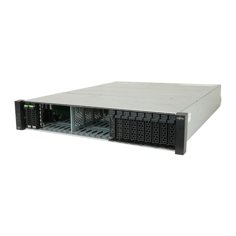
Figure 66 Front View of a 2.5" Type Drive Enclosure...............................................................................................243
Figure 67 Front View of a 3.5" Type Drive Enclosure...............................................................................................243
Figure 68 Front View of a High-Density Drive Enclosure.........................................................................................244
Figure 69 Top View of a High-Density Drive Enclosure with the Cover Opened.......................................................245
Figure 70 Rear View of a 2.5"/3.5" Type Drive Enclosure (When Only One I/O Module Is Installed).........................246
Figure 71 Rear View of a 2.5"/3.5" Type Drive Enclosure (When Two I/O Modules Are Installed) ............................246
Figure 72 Rear View of a High-Density Drive Enclosure..........................................................................................247
Figure 73 Operation Panel (Drive Enclosure) .........................................................................................................248
Figure 74 Disk Activity Panel (DAP)........................................................................................................................249
Figure 75 2.5" Drives and 3.5" Drives .....................................................................................................................250
Figure 76 I/O Module (Drive Enclosure)..................................................................................................................251
Figure 77 Power Supply Unit (Drive Enclosure) (AC Power Type)............................................................................252
Figure 78 Power Supply Unit (Drive Enclosure) (DC Power Type) ...........................................................................252
Figure 79 Fan Expander Module ............................................................................................................................253
Figure 80 Power Distribution Units (1U) ................................................................................................................254
Figure 81 Power Distribution Units (2U) ................................................................................................................254
Figure 82 Basic Concept of Host Connection (When Using Host Groups)................................................................255
List of Figures
7 Configuration Guide (Basic)

