Fukuda Denshi PaoLus UF-760AG User manual

FULL DIGITAL
DIAGNOSTIC ULTRASOUND
IMAGING EQUIPMENT
UF-760AG
Ver.01
Instructions for Use
Keep this guide near the unit for future reference.
Complementary information can be found in the system operation manual.

The device bears the CE label in accordance with the provisions of Medical Device Directive 2007/
47/EC.
THE PERSONS RESPONSIBLE FOR PLACING DEVICES
ON THE EC MARKET UNDER MDD 2007/47/EC.
NAME : FUKUDA DENSHI UK
ADDRESS: 13 WESTMINSTER COURT, HIPLEY STREET
OLD WOKING, SURREY GU22 9LG, UK
This “Instructions for Use” Guide provides you all required information for safe oper-
ation of the device. For more details please refer to the Operation Manual of the unit.
Copyright © 2011 by Fukuda Denshi Co., Ltd.
No part of this document may be copied or reproduced in any form without the prior written permis-
sion of Fukuda Denshi Co., Ltd.
Printed in Japan.
Caution
Note for U.S. Customers:
`Federal law restricts this device to be sold by or on the order of a physician.
Info:
`Only physicians or persons instructed by physicians are allowed to use this equipment.
`The information contained in this document is subject to change without notice due to
improvements in the equipment.
EC REP
This Instructions for Use Guide is for the UF-760AG Version 01.

1
1 INTRODUCTION . . . . . . . . . . . . . . . . . . . . . . . . . . . . . . . . . . . . . . . . . . . . . . . . . . . 1-2
1.1 Welcome! . . . . . . . . . . . . . . . . . . . . . . . . . . . . . . . . . . . . . . . . . . . . . . . . . . . . . . . . . . . . 1-2
1.2 Copyright. . . . . . . . . . . . . . . . . . . . . . . . . . . . . . . . . . . . . . . . . . . . . . . . . . . . . . . . . . . . . 1-2
1.3 Compliance with standards. . . . . . . . . . . . . . . . . . . . . . . . . . . . . . . . . . . . . . . . . . . . . . . 1-2
1.4 Cautions on Safety . . . . . . . . . . . . . . . . . . . . . . . . . . . . . . . . . . . . . . . . . . . . . . . . . . . . . 1-3
1.4.1 Symbols and meanings of warning labels . . . . . . . . . . . . . . . . . . . . . . . . . . . . . . . . .1-3
1.4.2 Before Use . . . . . . . . . . . . . . . . . . . . . . . . . . . . . . . . . . . . . . . . . . . . . . . . . . . . . . . . .1-3
1.4.3 Important Warning Items . . . . . . . . . . . . . . . . . . . . . . . . . . . . . . . . . . . . . . . . . . . . . .1-4
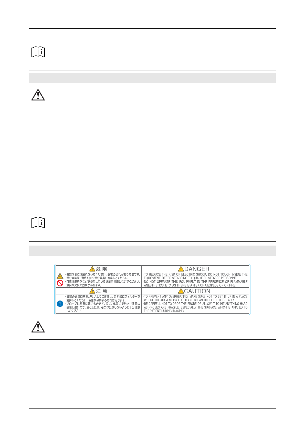
1.4.4 Warning Labels on the instrument . . . . . . . . . . . . . . . . . . . . . . . . . . . . . . . . . . . . . . .1-4
1.5 Acoustic Output and Patient Safety . . . . . . . . . . . . . . . . . . . . . . . . . . . . . . . . . . . . . . . . 1-5
2 SYSTEM INTRODUCTION . . . . . . . . . . . . . . . . . . . . . . . . . . . . . . . . . . . . . . . . . . . 2-2
2.1 Basic description of the system . . . . . . . . . . . . . . . . . . . . . . . . . . . . . . . . . . . . . . . . . . . 2-2
2.1.1 Front View . . . . . . . . . . . . . . . . . . . . . . . . . . . . . . . . . . . . . . . . . . . . . . . . . . . . . . . . .2-2
2.1.2 Side View . . . . . . . . . . . . . . . . . . . . . . . . . . . . . . . . . . . . . . . . . . . . . . . . . . . . . . . . . .2-2
2.1.3 Rear View. . . . . . . . . . . . . . . . . . . . . . . . . . . . . . . . . . . . . . . . . . . . . . . . . . . . . . . . . .2-2
2.2 Connecting the power cord and the ground wire . . . . . . . . . . . . . . . . . . . . . . . . . . . . . . 2-2
2.2.1 Power cord . . . . . . . . . . . . . . . . . . . . . . . . . . . . . . . . . . . . . . . . . . . . . . . . . . . . . . . . .2-2
2.2.2 Ground wire . . . . . . . . . . . . . . . . . . . . . . . . . . . . . . . . . . . . . . . . . . . . . . . . . . . . . . . .2-2
2.3 Connecting probes . . . . . . . . . . . . . . . . . . . . . . . . . . . . . . . . . . . . . . . . . . . . . . . . . . . . . 2-3
2.4 Power ON and Power OFF. . . . . . . . . . . . . . . . . . . . . . . . . . . . . . . . . . . . . . . . . . . . . . . 2-3
2.5 Control Panel Tour . . . . . . . . . . . . . . . . . . . . . . . . . . . . . . . . . . . . . . . . . . . . . . . . . . . . . 2-4
2.6 Relocation / Installation. . . . . . . . . . . . . . . . . . . . . . . . . . . . . . . . . . . . . . . . . . . . . . . . . . 2-5
2.7 Menu Operation . . . . . . . . . . . . . . . . . . . . . . . . . . . . . . . . . . . . . . . . . . . . . . . . . . . . . . . 2-5
2.8 Configuring my preferences . . . . . . . . . . . . . . . . . . . . . . . . . . . . . . . . . . . . . . . . . . . . . . 2-6
2.8.1 How to get started? . . . . . . . . . . . . . . . . . . . . . . . . . . . . . . . . . . . . . . . . . . . . . . . . . .2-6
2.8.2 How to change general system settings?. . . . . . . . . . . . . . . . . . . . . . . . . . . . . . . . . .2-6
2.8.3 How to install a new printer? . . . . . . . . . . . . . . . . . . . . . . . . . . . . . . . . . . . . . . . . . . .2-7
2.8.4 How to assign functions to the REC keys?. . . . . . . . . . . . . . . . . . . . . . . . . . . . . . . . .2-8
2.8.5 How to connect my system to a network? . . . . . . . . . . . . . . . . . . . . . . . . . . . . . . . . .2-8
2.8.6 How to configure my Measurement list? . . . . . . . . . . . . . . . . . . . . . . . . . . . . . . . . . .2-9
2.8.7 How to set Obstetric curves by default?. . . . . . . . . . . . . . . . . . . . . . . . . . . . . . . . . . .2-9
3 STARTING AN EXAM. . . . . . . . . . . . . . . . . . . . . . . . . . . . . . . . . . . . . . . . . . . . . . . 3-2
3.1 Managing Patients . . . . . . . . . . . . . . . . . . . . . . . . . . . . . . . . . . . . . . . . . . . . . . . . . . . . . 3-2
3.1.1 Searching for a patient . . . . . . . . . . . . . . . . . . . . . . . . . . . . . . . . . . . . . . . . . . . . . . . .3-2
3.1.2 Accessing an old study. . . . . . . . . . . . . . . . . . . . . . . . . . . . . . . . . . . . . . . . . . . . . . . .3-2
3.2 Starting an Exam . . . . . . . . . . . . . . . . . . . . . . . . . . . . . . . . . . . . . . . . . . . . . . . . . . . . . . 3-3
3.2.1 Enter a new patient. . . . . . . . . . . . . . . . . . . . . . . . . . . . . . . . . . . . . . . . . . . . . . . . . . .3-3
3.2.2 Selecting Probe and Application. . . . . . . . . . . . . . . . . . . . . . . . . . . . . . . . . . . . . . . . .3-3
3.3 Making an Examination. . . . . . . . . . . . . . . . . . . . . . . . . . . . . . . . . . . . . . . . . . . . . . . . . . 3-4
3.3.1 Screen display tour. . . . . . . . . . . . . . . . . . . . . . . . . . . . . . . . . . . . . . . . . . . . . . . . . . .3-4
3.3.2 Adjusting brightness and contrast . . . . . . . . . . . . . . . . . . . . . . . . . . . . . . . . . . . . . . .3-4
3.3.3 Working in B/M-mode. . . . . . . . . . . . . . . . . . . . . . . . . . . . . . . . . . . . . . . . . . . . . . . . .3-5
3.3.4 Working in PW/CW-mode. . . . . . . . . . . . . . . . . . . . . . . . . . . . . . . . . . . . . . . . . . . . . .3-6
3.3.5 Working in CFM mode . . . . . . . . . . . . . . . . . . . . . . . . . . . . . . . . . . . . . . . . . . . . . . . .3-7
3.3.6 Working in 3D/4D mode . . . . . . . . . . . . . . . . . . . . . . . . . . . . . . . . . . . . . . . . . . . . . . .3-8
3.3.7 Working with EasyOptim (option). . . . . . . . . . . . . . . . . . . . . . . . . . . . . . . . . . . . . . . .3-9
3.3.8 Working with Spatial Compounding (option) . . . . . . . . . . . . . . . . . . . . . . . . . . . . . . .3-9

2
3.4 Image Management . . . . . . . . . . . . . . . . . . . . . . . . . . . . . . . . . . . . . . . . . . . . . . . . . . . 3-10
3.5 Review the study content . . . . . . . . . . . . . . . . . . . . . . . . . . . . . . . . . . . . . . . . . . . . . . . 3-10
3.6 Create a Report . . . . . . . . . . . . . . . . . . . . . . . . . . . . . . . . . . . . . . . . . . . . . . . . . . . . . . 3-10
3.7 Printing Images/Reports . . . . . . . . . . . . . . . . . . . . . . . . . . . . . . . . . . . . . . . . . . . . . . . . 3-10
4 ANNOTATIONS AND MEASURES . . . . . . . . . . . . . . . . . . . . . . . . . . . . . . . . . . . . 4-2
4.1 Annotations. . . . . . . . . . . . . . . . . . . . . . . . . . . . . . . . . . . . . . . . . . . . . . . . . . . . . . . . . . . 4-2
4.2 Measures . . . . . . . . . . . . . . . . . . . . . . . . . . . . . . . . . . . . . . . . . . . . . . . . . . . . . . . . . . . . 4-3
4.2.1 B-mode basic measurements. . . . . . . . . . . . . . . . . . . . . . . . . . . . . . . . . . . . . . . . . . .4-3
4.2.2 M-mode basic measurements . . . . . . . . . . . . . . . . . . . . . . . . . . . . . . . . . . . . . . . . . .4-4
4.2.3 PW/CW-mode basic measurements . . . . . . . . . . . . . . . . . . . . . . . . . . . . . . . . . . . . .4-5
5 MANAGING PATIENT DATABASE . . . . . . . . . . . . . . . . . . . . . . . . . . . . . . . . . . . . 5-2
5.1 Import/Export . . . . . . . . . . . . . . . . . . . . . . . . . . . . . . . . . . . . . . . . . . . . . . . . . . . . . . . . . 5-2
5.2 Backup and Recovery Tool. . . . . . . . . . . . . . . . . . . . . . . . . . . . . . . . . . . . . . . . . . . . . . . 5-3
5.2.1 Patient Database Backup and Restore . . . . . . . . . . . . . . . . . . . . . . . . . . . . . . . . . . .5-3
5.2.2 Backup and Restore of User Preferences and setups . . . . . . . . . . . . . . . . . . . . . . . .5-4
6 MAINTENANCE . . . . . . . . . . . . . . . . . . . . . . . . . . . . . . . . . . . . . . . . . . . . . . . . . . . 6-2
6.1 Check Procedures . . . . . . . . . . . . . . . . . . . . . . . . . . . . . . . . . . . . . . . . . . . . . . . . . . . . . 6-2
6.2 Cleaning and Disinfection. . . . . . . . . . . . . . . . . . . . . . . . . . . . . . . . . . . . . . . . . . . . . . . . 6-2
6.2.1 System . . . . . . . . . . . . . . . . . . . . . . . . . . . . . . . . . . . . . . . . . . . . . . . . . . . . . . . . . . . .6-2
6.2.2 Probes . . . . . . . . . . . . . . . . . . . . . . . . . . . . . . . . . . . . . . . . . . . . . . . . . . . . . . . . . . . .6-3
6.3 Product recycling and disposal. . . . . . . . . . . . . . . . . . . . . . . . . . . . . . . . . . . . . . . . . . . . 6-3
A APPENDIX A: Technical Specifications. . . . . . . . . . . . . . . . . . . . . . . . . . . . . . . A-2
A.1 General. . . . . . . . . . . . . . . . . . . . . . . . . . . . . . . . . . . . . . . . . . . . . . . . . . . . . . . . . . . . . . A-2
A.1.1 Intended Use . . . . . . . . . . . . . . . . . . . . . . . . . . . . . . . . . . . . . . . . . . . . . . . . . . . . . . A-2
A.1.2 Display Modes . . . . . . . . . . . . . . . . . . . . . . . . . . . . . . . . . . . . . . . . . . . . . . . . . . . . . A-2
A.1.3 System Architecture . . . . . . . . . . . . . . . . . . . . . . . . . . . . . . . . . . . . . . . . . . . . . . . . . A-2
A.2 Ultrasound Application . . . . . . . . . . . . . . . . . . . . . . . . . . . . . . . . . . . . . . . . . . . . . . . . . . A-3
A.2.1 B-mode (2D). . . . . . . . . . . . . . . . . . . . . . . . . . . . . . . . . . . . . . . . . . . . . . . . . . . . . . . A-3
A.2.2 M-Mode . . . . . . . . . . . . . . . . . . . . . . . . . . . . . . . . . . . . . . . . . . . . . . . . . . . . . . . . . . A-3
A.2.3 Spectral Doppler Modes. . . . . . . . . . . . . . . . . . . . . . . . . . . . . . . . . . . . . . . . . . . . . . A-3
A.2.4 Color Doppler and Power Doppler Modes, Color M mode. . . . . . . . . . . . . . . . . . . . A-3
A.2.5 ECG . . . . . . . . . . . . . . . . . . . . . . . . . . . . . . . . . . . . . . . . . . . . . . . . . . . . . . . . . . . . . A-4
A.3 Database, Measurements, Reporting. . . . . . . . . . . . . . . . . . . . . . . . . . . . . . . . . . . . . . . A-4
A.3.1 Archiving and Communication . . . . . . . . . . . . . . . . . . . . . . . . . . . . . . . . . . . . . . . . . A-4
A.3.2 Measurements . . . . . . . . . . . . . . . . . . . . . . . . . . . . . . . . . . . . . . . . . . . . . . . . . . . . . A-4
A.3.3 Annotations. . . . . . . . . . . . . . . . . . . . . . . . . . . . . . . . . . . . . . . . . . . . . . . . . . . . . . . . A-4
A.3.4 Input/Output . . . . . . . . . . . . . . . . . . . . . . . . . . . . . . . . . . . . . . . . . . . . . . . . . . . . . . . A-4
A.4 Environmental Conditions. . . . . . . . . . . . . . . . . . . . . . . . . . . . . . . . . . . . . . . . . . . . . . . . A-5
A.4.1 Electrical Specifications . . . . . . . . . . . . . . . . . . . . . . . . . . . . . . . . . . . . . . . . . . . . . . A-5
A.4.2 Environment . . . . . . . . . . . . . . . . . . . . . . . . . . . . . . . . . . . . . . . . . . . . . . . . . . . . . . . A-5
A.4.3 Regulations and Safety . . . . . . . . . . . . . . . . . . . . . . . . . . . . . . . . . . . . . . . . . . . . . . A-5
A.4.4 Physical Dimensions . . . . . . . . . . . . . . . . . . . . . . . . . . . . . . . . . . . . . . . . . . . . . . . . A-5
A.5 Probes. . . . . . . . . . . . . . . . . . . . . . . . . . . . . . . . . . . . . . . . . . . . . . . . . . . . . . . . . . . . . . . A-6

1-2 Welcome!
1 INTRODUCTION
Thank you for purchasing the UF-760AG system.
Intended readers:
Medical Doctors and clinicians using the equipment.
Thank you for purchasing the UF-760AG.
Your instrument is equipped with the following features:
• Multi-beam processing and frequency compound imaging technology
• Advanced tissue echo cancellation for superb Color Doppler and Power Doppler
• Smart harmonic imaging and three axis filtering for excellent image quality
•High brightness LCD monitor
• High sensitivity wide band probes
• Simple operability
The information contained in this publication may not be used for any purpose other than that for
which it was originally supplied. The publication may not be reproduced in part or in whole without
the written consent of FUKUDA DENSHI. FUKUDA DENSHI may not be held liable for any error con-
tained in this publication or any damage related to use of equipment. FUKUDA DENSHI reserves the
right to revise this publication. Amendments may therefore be made without prior notice.
UF-760AG, manufactured by FUKUDA DENSHI, fully complies with the Council Directive 2007/47/
EC concerning medical devices and bears the CE mark.
FUKUDADENSHI hasdefinedUF-760AGasUltrasounddiagnosticequipmentinClassIIa according
to Annex of the directive.
The UF-760AG is in compliance with:
•MDD
• Japanese pharmaceutical affairs law
• German K.V. regulation
• IEC 60601-1 Class I Type BF (electrical Safety)
• IEC 61157 (Acoustic power reporting)
• IEC 60601-2-37
• JIS T0601-1
• FDA 510(k)
1 INTRODUCTION
1.1 Welcome!
1.2 Copyright
1.3 Compliance with standards

1
1 INTRODUCTION
Cautions on Safety 1-3
The following signs indicate the extent of injury or damage due to incorrect handling of the equipment
without observing the warning precautions.
1.4 Cautions on Safety
1.4.1 Symbols and meanings of warning labels
Danger:
`Failure to follow this message can result in death or serious injury of the patient or operator,
or cause imminent danger of fire.
Warning:
`Failure to follow this message can result in death or serious injury of the patient or operator,
or create a fire hazard.
Caution:
`Failure to follow this message can cause injury to the patient or operator, or may cause dam-
age to the equipment.
For your information:
`Information, to make your work easier.
`mark is indicated on the main unit of the equipment for protecting it from damage.
1.4.2 Before Use
Caution:
`Never use the equipment unless you are a skilled operator.
`According to the description of the different techniques of the system and the different appli-
cations, the user can be only a physician with graduate medicine school or a trained sonogra-
pher.
`The real patient population is composed of any person needing an harmless and non real
invasive examination (invasive examinations are only made through natural orifices). This
person, healthy or not, can be an adult or a child.
`Ultrasound examination can be performed for different purposes and on different body parts.
`Be sure of not exceed the time and quantity required for diagnosis or medical treatment.
`Always monitor the unit and the patient to make sure they are normal.
Caution:
Observe the following when installing the system:
`Install the unit in a place where it is not exposed to water and in a place free from excessive
atmospheric pressure, humidity, ventilation, sunlight, etc., which may affect the performance
of the unit.
`Install the unit in a stable place.
`Make sure the unit is properly grounded.
`Do not remove the protective cover from the equipment.
`Do not modify the equipment.
`Do not reproduce the equipment.
`Do not allow alcohol, water or other liquids to enter the device interior.
`Do not use the system near an MRI.
Caution of Power Voltage:
`The equipment must be operated with the specified input power voltage.
Maintenance and inspection
`Maintenance and inspection are essential for finding signs of physical damage to the equip-
ment, connectors, and all cables.

1-4 Cautions on Safety
1 INTRODUCTION
For your information:
`For more detailed information about Cautions on Safety please refer to UF760AG Operation
Manual (Chapter 1 “INTRODUCTION” on page 1-1) to ensure a safe and proper manipula-
tion of the system.
1.4.3 Important Warning Items
Warning:
Connecting the Power Cord
`Be sure to connect the power cord to a medical-use 3-pin receptacle.
`If potential equalization is required, connect the potential equalization terminal of the equip-
ment and the terminal for potential equalization with the ground wire (equalization of the
ground potential).
`Use a power cord that is approved for use in your area.
Power ON
`Do not use the equipment with a defibrillator.
`If the equipment is used with an electro-surgery, check the connection of the counter elec-
trode plate otherwise skin burns can occur.
Physiological Signal Display
`The ECG module is not designed for electrocardiography or monitoring. Do not use it for
diagnosis.
Connecting a Patient Cable
`Inspect the patient cable before using the equipment.
`If a cardiac pacemaker or other electrically stimulant equipment is connected to the patient,
danger to the patient may result.
Power OFF
`Do not turn OFF the power while you are accessing the USB memory or the HDD.
For your information:
`For more detailed information about Cautions on Safety please refer to UF760AG Operation
Manual (Chapter 1 “INTRODUCTION” on page 1-1) to ensure a safe and proper manipula-
tion of the system.
1.4.4 Warning Labels on the instrument
Warning:
`Do not break, damage or obliterate the warning labels attached to the equipment.

1
1 INTRODUCTION
Acoustic Output and Patient Safety 1-5
Thermal Index (TI)
TI is determinate by the ratio of the total acoustic power to the acoustic power required to raise the
tissue temperature by 1°C. In addition, and due to the fact the temperature increases greatly different
according to tissue structures, three kinds of TI are distinguished: TIS (Soft-tissue Thermal Index),
TIB (Bone Thermal Index) and TIC (Cranial-bone thermal Index).
Although the output power is automatically controlled for the selected applications, high TI values
should be kept to a minium or avoided in Obstetric applications. WFUMB (World Federation for Ul-
trasound in Medicine and Biology) guidelines state that a temperature increase of 4°C for 5 minutes
or more should be considered as potentially hazardous to embryonic and fetal tissue.
Mechanical Index (MI)
The mechanical bioeffects are the result of compression and decompression of insonated tissues
with the formation of micro bubbles that may be referred as cavitations.
MI is an index that shows the possibility of appearing cavitations based on acoustic pressure. It is
important to keep the MI value low when both gases and soft tissues are encountered, in cases like
lung exposure in cardiac scanning or bowel gas in abdominal scanning.
Display of TI and MI values
TI and MI values are displayed in real time in the lower left part of the screen. The operator should
monitor these index values during examinations and ensure that exposure time and output values
are maintained at the minimal amounts needed for effective diagnosis.
The TI and MI values are displayed in increments of 0.2. Index values below 0.4 are displayed by the
system as <0.4. To optimize ALARA, index values that are equal or higher than 0.4, are displayed
even if the maximal index value does not exceed 1.0.
Maximum Ultrasound Output
The UF-760AG meets FDA Track 3 requirements and the maximum ultrasound output with real time
displayed of TI and MI indexes is limited as follows:
ALARA (As Low As Reasonably Achievable)
This principle mandates that ultrasound output power and exposure time are kept to the minimum
requiredwithout compromising diagnostic capability or resolution. While therehavebeennoreported
incidents of serious bioeffects in humans for diagnostic ultrasound levels, itis known that an increase
of tissue temperature may occur and that can lead to possible cavitations.
1.5 Acoustic Output and Patient Safety
Intended Use ISPTA.3 MI
Vascular; Cardiac; Abdominal and Ob/Gyn ap-
plications 720 mW/cm21.9
Ophthalmic application is not supported by UF-760AG.
For your information:
`ISPTA.3: Spatial peak time average intensity with consideration given to attenuation.

1-6 Acoustic Output and Patient Safety
1 INTRODUCTION

2-2 Basic description of the system
2 SYSTEM INTRODUCTION
This chapter only describes in a very briefly way the installation and basic configuration of the system
and does not replace the reading of the Operation Manual before system operation, in order to en-
sure a safe installation of the device.
2 SYSTEM INTRODUCTION
2.1 Basic description of the system
2.1.1 Front View
POWER
Switch
Monitor
Handle
Operation
Panel
2.1.2 Side View
2.1.3 Rear View
Probe Receptacle
FAN DC
input
USB
connectors
LAN
Video Out Equalization
terminal
i/o Extension
Unit connector
This section describes how to connect the power cord and the ground wire to the system.
Do not turn ON the power of the equipment until the preparation for operation is completed
2.2 Connecting the power cord and the ground wire
Attention:
`Do not attempt connection or disconnection of the cables with wet hands. Electric shock,
short-circuit and risk of fire may occur.
`Do not connect the equipment with non-medical electrical equipment which does not conform
with the safety standards of ISO or IEC.
Connect the AC adapterpower cordto the DC in-
put connector at the rear side of the system.
Connect the power cord to the power connector
of the AC adapter. Connect the power cord plug
(3P) to the medical-use 3-pin receptacle of the
power supply.
Connect the ground wire like shown below.
Before using the equipment connected to a pe-
ripheral device (such as VCR or line printer), be
sure to use an isolation transformer for medical
instruments, and connect the potential equaliza-
tion terminal of the equipment and the ground
terminal of the peripheral device with the ground
wire.
2.2.1 Power cord
Power
cord
AC
Adapter
AC adapter
power cord
DC
input
2.2.2 Ground wire
Ground
Equalization wire
terminal

2
2 SYSTEM INTRODUCTION
Connecting probes 2-3
2.3 Connecting probes
For your information:
`Some UF-870AG probes (known as DL probes) can be used on UF-760AG system. A DL
adapter is available to bring to UF-760AG the same range of probes that are available on UF-
870AG.
Connecting UF-760AG probes
Connect the probe connector to the probe recepta-
cle.
Turn the lever on the probe connector clockwise
90° to lock the probe connector.
Connecting probes using a DL adapter
Connect the DL probe adapter to the probe recep-
tacle.
Turn the lever on the probe adapter clockwise 90°
to lock the probe adapter.
Connect the DL probe connector to the DL probe
adapter.
Turn the lever on the probe connector clockwise
90° to lock the DL probe.
For your information:
`To connect a pencil probe to your system you only have to plug it in the corresponding con-
nector.
2.4 Power ON and Power OFF
Power ON
Open the LCD screen.
Connect the ultrasound probe to be used to the
system.
Press the [POWER] key on the opera-
tion panel.
9
After a short period of time the initial
screen appears.
Makesurethatanyperipheraldevicesarecorrectly
connected.
Power OFF
Press the [POWER] key on the operation panel.
The power OFF confirmation dialog appears.
Move the arrow mark to the desired option and
press the [SET] key or press [ENTER] key.
9
Select “Stand by” if youwant to set the system
to low power mode and able to restart in 10
seconds.
9
Select “Hibernate” if you want to suspend the
system to DISK.
9
Select “Cancel” to abort this process.
9
Select “Shut down” if you want to completely
stop the system.
For your information:
`For daily usage it is recommended to use the option “Shut down” rather than “Stand by” or
“Hibernate”.
Probe
receptacle
Lever
Probe connector
DL probe
adapter
Probe
receptacle
connector
Probe
Pencil Probe
Connector

2-4 Control Panel Tour
2 SYSTEM INTRODUCTION
2.5 Control Panel Tour
(1) Alphanumeric Keyboard
Use the keyboard to enter patient
information and annotations.
(2) STC gain sliders
Move slide pots left/right to adjust
STC gain.
(3) Zoom/Depth knob
Press the knob to select either
zoom or depth. Rotate the key to
adjust the selected parameter.
(4) 4D key
Press this key to enter on 3D/4D
mode.
(5) Easy Optim key
Press this key to automatically op-
timize your image (refer to Chap-
ter3.3.7"WorkingwithEasyOptim
(option)" on page 3-9 to further in-
formation).
(6) Mode keys
B-mode;M-mode;CFM;PWand
CW keys. Press these keys to
select the desired mode.
(7) Freeze key
Suspends real time.
(8) Gain knobs
B/M-mode and PW/CW/CFM
gain knobs. Rotate the key to ad-
just the gain.
(9) Body Marker; Comment; Mea-
surement and Pointer keys
Press these keys to enter on the
desired mode.
(10)REC keys
Press these keys to print or ex-
port images.
(11)Doppler Parameters keys
Press up/down these keys to op-
timize Doppler image.
(12)Probe key
Press this key to access the
probe screen.
(13)Patient key
Pressthiskey to enteronPatient
screen.
(14)POWER key
Press this key to power ON/OFF
the unit.
(2)
(1)
(6)
(8)
(9)
(7)
(10)
(3)
(11)
(12)
(13)
(14)
(5)
(4)

2
2 SYSTEM INTRODUCTION
Relocation / Installation 2-5
The equipment is provided with a handle for transporting. To relocate and install the unit, follow the
procedure shown below.
This section explains the menu operation method. The General menus, also called soft keys menus,
are the principal menus of the system and include the items for image quality adjustment and execu-
tion of multiple functions.
All the main functionalities corresponding to the current system state (e.g. current ultrasound mode),
except those reached directly through the ultrasound keyboard keys, are displayed in this kind of
menus.
2.6 Relocation / Installation
Pressthe[POWER]key on theoperationpaneltoturnOFFtheunit.
The power OFF confirmation dialog appears.
Select “Shut down” and press the [SET] key or press [ENTER] key.
Close the LCD screen.
IftheunitisconnectedtoACpower,disconnectthepowercordplug
and wrap the power cord before transporting the device.
Move the equipment to the desired place.
2.7 Menu Operation
Select a menu item
Use the FUNCTION keys ([F1] to [F6]) on the operation
panel to select a menu item. The numeric value on the
screenandthe value oftheFUNCTION keys correspond
to each other.
Changing menu pages
Pages can be switched by pressing up and down the
[PAGE] keys. Press the [PAGE] down key to display the
next page and the [PAGE] up key to display the previous
page.
Changing settings
Press the up or down FUNCTION key, and the setting is
switched.
POWER
Switch
1 Left 2 Angle 3 Gamma 4 Enhance 5Smooth6Noise
Menu Display
FUNCTION keys
PAGE keys
Reject

2-6 Configuring my preferences
2 SYSTEM INTRODUCTION
The UF-760AG functionalities can be arranged according to the physician preferences.
In order to create his own system configuration, the user only has to press the [SETUP MENU] key,
reachable through the keyboard, and set his preferences. These new settings are saved on the sys-
tem and reloaded at each system startup.
In the Setup Menu, the user can also have access to system information and status.
Power ON your system by pressing on [POWER] switch.
Press [Setup Menu] key on the keyboard to start configuring the device.
The following screen is displayed:
Select the desired group in the menu entries.
Click on a tab to open the related page in the Setup Dialog window.
In this section are described the most general actions that you can perform to set up your system
according to your preferences.
To start configuring the device follow the next steps:
Press [Setup Menu] key.
Select <Gen. Set> menu.
9
Here you can define some of your preferences:
2.8 Configuring my preferences
For your information:
`Only basic settings are described in this chapter. To have a full and detailed description of the
Setup Menu and a complete overview of the procedure to set you preferences please refer to
Chapter “5 ADVANCED OPERATION” on page 5-1 of the Operation Manual.
2.8.1 How to get started?
The parameters that can be configured ac-
cording to your preferences are divided in 5
different groups:
•Device Information (General, Host Info, User
storage devices,...)
•General system settings (System prefer-
ences, Network and printing configuration,...)
•Ultrasound settings (Ultrasound, Application,
Display, Exporting,...)
•Measurement settings (Advanced Measure-
ment List, OB settings,...)
•Stress Echo (Settings, Protocols) (optional)
Each page of the Setup menu corresponds to
a group of parameters. Every group includes
several pages.
2.8.2 How to change general system settings?
Configuration Data
Type
Serial number
System ID
UF-870
50000002
0349-5600-0256-0503-0107
DEA5 5D5D 08A9 3903
Configuration Key
Advanced...
0107
4D
CW
DICOM Modality Worklist
Stress Echo
DICOM StoragellSCU
Cardio
Host Info System Temperature Software/Firmware info Hardware info
User Storage Devices
General
FUKUDA.Hosp 11:35:45
1234 56
Options:
01/21/2011
US.Set Refresh Reset Apply
Gen. Set
Dev. Info

2
2 SYSTEM INTRODUCTION
Configuring my preferences 2-7
Press [Setup Menu] key.
Select <Gen. Set> menu.
Select <Printer Settings> tab.
Printer Settings tab is divided in two different types: printer and video printer. According to the cho-
sen printer type (line printer or video printer), the user will set the definitions on the corresponding
menu.
Change system language
Select the desired language and press <Apply> to vali-
date the new configuration.
Change Laboratory information
Insert the different laboratory information using the alpha-
numeric keyboard and press <Apply> to confirm the intro-
duced data.
Change Laboratory Logo
Select [Change Logo], plug in a USB stick and load your
logo file (BMP, PNG, JPEG).
The size of the logo is scaled automatically to fit to the re-
port.
Change system time zone, date and time
On “Time” field, click on the [Arrow Up] to increase the
digit (hour, minutes or seconds; it depends of what you
had selected) or click on the [Arrow Down] to decrease
the digit.
On “Time zone” field, select your continent and your
country’s capital and then, select <Validate> to change
the Time zone of the system.
On “Date” field, click on the [Arrow Up] to increase the
digit (day, month or year; it depends of what you had se-
lected) or click on the [Arrow Down] to decrease the digit.
Press <Apply> to validate the new configuration.
2.8.3 How to install a new printer?
Attention:
`Before connecting the system with other devices, be sure to read the Appendix B “Installa-
tion/Connection of peripheral devices” of the Operation Manual, to ensure a safe connection
of the system with other equipments.
`Never connect additional peripherals directly to wall outlets if there is no isolator to provide
galvanic isolation between the peripheral and the system. Wrong connections may compro-
mise the electrical safety of the system.
Line Printer configuration
• USB Printer:
`Select the printer in the list of available print-
ers. To appear in the list, the printer must be
connected to the system and powered ON.
`Select the resolution and page size.
`Press <Apply> to validate the printer configu-
ration. You can start using the device without
restarting the system.
• Network printer:
`Select the printer in the list of available print-
ers. All the printers installed on the system will
appear in this list.
`Enter the IP address and press <Test> to ver-
ify its coherence.
`Select the resolution and page size.
`Press <Apply> to validate the printer configu-
ration. You can start using the device without
restarting the system.
Video Printer configuration
`Select the printer in the list of available digital
printers. To appear in the list, the printer must
be connected to the system and powered ON.
Depending on the printer, some parameters
such as image size can be configured.
`If you want to connect an analog printer to the
system, select “Analog Video Printer” entry in
the list.
`Press <Apply> to validate the printer configu-
ration. The printer can be used without restart-
ing the system.
For your information:
`All the printers that can be connected to UF-760AG are listed on the Operation Manual
(Appendix B “Installation/Connection of peripheral devices”).

2-8 Configuring my preferences
2 SYSTEM INTRODUCTION
Press [Setup Menu] key.
Select <US. Set.> menu.
Select <Archiving> tab.
For each REC key, move the pointer at the corresponding drop down list and press [SET].
Depending on the first selected action, more than one preference can be selected for the REC keys:
Press <Apply> to validate your choice.
Press [Setup Menu] key.
Select <Gen. Set> menu.
Select <Network configuration> tab.
Be sure that your system is connected to a network and then click on “Enable Network” box to enable the
network at the next system startup.
2.8.4 How to assign functions to the REC keys?
<Empty string>
Nothing is assigned to the key.
Archive (Default action for [REC1])
The displayed still image is stored in the Database.
Print on video printer 1 or print on video printer 2
The displayed still image is printed out on the video print-
er defined as “Video Printer 1 or 2”, on the “Printer Set-
tings” screen.
Archive Clip (Default action for [REC2])
The current cine loop is stored in the Database. The num-
ber of stored images depends on the “Stored cine clip du-
ration”parameter(refer to Operation Manual - Chapter 5-
to know more).
EasyPrint (Default action for [REC3])
Print images/report on a line printer.
Export Study Data to Default Export folder or to USB
stick
All study data (images, clips, finding records and reports)
are stored on the Default Export Folder or USB stick.
Archive 4D bookmark
The current 4D data is stored on the Database. This set-
tings is only available when 4D option is enabled.
Direct Export to Export folder or to USB stick
The displayed still image is exported to the Export folder
or USB stick.
2.8.5 How to connect my system to a network?
For your information:
`Refer to the Operation manual of the system (Chapter 5 “Advanced Operation”) to have fur-
ther information concerning network connection.

2
2 SYSTEM INTRODUCTION
Configuring my preferences 2-9
Press [Setup Menu] key.
Select <Meas.> menu at second menu page.
Select “Adv. Meas. list” tab.
Press [Setup Menu] key.
Select <Meas.> menu at second menu page.
Select “OB Settings” tab.
2.8.6 How to configure my Measurement list?
On this screen, the different advanced measure-
ments implemented in the system are grouped by
medical application and measurement group.
You can select the advanced measurements that
you want to use.
Usingthetrackballand the[SET] key, selectthe
medical application and the measurement
group to configure.
Double click on the Medical application name
will disable the check-box and all the measure-
ments and measurement groups belonging to
the Medical application will be disabled as well.
Double click on the Measurement group will dis-
able the check-box and the Measurement
Group and all measurements belonging to it will
appear disabled as well.
Click on the measurement check-box will dis-
able the chosen measurement.
Select <Apply> to store the Advanced Measure-
ment list.
2.8.7 How to set Obstetric curves by default?
The“OBSettings”taballowstoselect the preferred
Obstetrics measurement curves and add new Ob-
stetrics curves (please refer to Chapter 5 “Ad-
vanced Operation” in the Operation Manual to
know more).
For each Obstetric measurement using curves a
default biometrical curve or formula has to be de-
fined. The estimated Fetal Age or Weight is than
computed from distance or circumference mea-
surement and from a biometrical curve or formula.
Move the trackball on the “select” icon of the
curve.
Press [SET] key to display the biometrical
curves/formulas drop down corresponding to
this measurement.
The selected curve is displayed.
Press <Apply> to validate your selection.
OB Settings
Adv.Meas.List
General
B EF.
LV Simpson
- LAD
LV Teich. (Abb)
LV Teich. (Full)
TEI IMP
LVO T
Ao_AV
LVS. Pl.
MV
PV
IVC
TV
Cont. Equa
Pulmonary Vein
- AoD
=> LAD/AoD
- AoRD
- AoArD
- AoAD
- AoVO
- LVOTD
=> LVOTA
- Vmax LVOT
- Vmax AO
=> PermIdx
=> AVA Vmax
=> AVAI V
- AoArv
- PHT AR
- RVOTD
- LAA
- AVA Trace
- AoVCD
- VTId Ao
-> MnGd Ao
-> Vmaxd Ao
-> PGd Ao
- VTIs Ao
Aortic Annulus Dimension
Aortic Root Dimension
Left Atrial Diameter
Aortic Valve Opening
Aortic Arch Dimension
Aortic PISA radius
Aorta Vena Contracta Diameter
Aortic Diameter
Aortic Cusp Separation
Aortic Leaflet Tip
Aortic Valve Area Trace
Aorta Maximal Velocity
End Diastolic Aortic Arch Velocity
Aortic Regurgitation Pressure Halt T
Aorta Systolic VTI
Aorta Diastolic VTI
Aorta Systolic Maximal Velocity
Aorta Systolic Peak Gradient
Aorta Systolic Mean Gradient
Aorta Diastolic Maximal Velocity
Left Ventricle Outflow Tract Diameter
Right Ventricle Outflow Tract Diameter
Left Ventricle Outflow Tract Maximal
Left Atrium Area
Sinotubular Junction Diameter
Abdominal
Cardiac
Ob/Gyn
SmallOrgans
PeriphVascular
LV Simpson S. Pl.
Medical
Application
Measurement
Group
Measurement
General Adv.Meas List
...
...
Tokyo Univ.
Tokyo Univ.
Jeanty
...
...
ᮏ
...
...
ᮏ
...
...
ᮏ
...
...
ᮏ
...
...
ᮏ
...
...
ᮏ
...
...
ᮏ
...
...
ᮏ
...
...
ᮏ
...
...
ᮏ
...
...
ᮏ
...
...
ᮏ
ᮏ...
...
...
...
ᮏ
...
OB Settings
Tokyo Univ.
Tokyo Univ.
Tokyo Univ.
Ramzin.
Osaka Univ.
Tokyo Univ.
Merz
Merz
Merz
Rampen
Hadlock
Lai,Yeo
Hansmann
Campbell
JSUM
ᮏ...
...
ᮏ
AC
APTD
AxT
BOD
BPD
ChD
CRL
FL
FTA
GES
HC
HuL
OFD
TTD
THD
LV
EFW
EFA(EFW)
Table
30
25
20
15
10
5
0
0510 15 20 25 30 35 40
Uncertaintly
wk
cm AC Tokyo Univ.
Curve

2-10 Configuring my preferences
2 SYSTEM INTRODUCTION
Table of contents