Fukuda FRE-203XR User manual

Laser Levels Online
Fukuda FRE-203XR
REVISION 1.1
User Guide
© 2021 Laser Levels Online

KEY INFORMATION
2
Specifi cation
Brand Fukuda
Product Type Rotating Laser Level
Levelling Type Fully Self Levelling
Detector Range Up to 500m Diameter (250m either side of Laser)
Accuracy ±2.8mm at 30m (100ft)
Beam Colour Red Beam
Beam Type Rotating Dot
Levelling Axis Horizontal & Vertical Levelling
Facilities 90° Squaring, Scan, Plumb (Up), Plumb (Down)
Usage Indoor & Outdoor
Battery Rechargeable Battery Pack or use Alkaline Batteries
Runtime Up to 50 Hours (Approx)
Slope / Gradient Dual Grade using Keypad or included Remote Control
Mounting Thread ⅝” Standard Surveying
Laser Rating Class 2
Durability Excellent
IP Rating IP66 - Dust tight / Protected against powerful jets of water
Warranty Automatic 3 Year Warranty

INTRODUCTION
Overview
SAFETY
WARNING
Thank you for purchasing the Fukuda FRE-203XR RED beam rotary laser kit.
These instructions are intended to explain the general basics of operating this equipment.
Please read them carefully.
For any more information, or if the laser requires calibration or repair; then please contact our
Service Department by Telephone: 08000 869 769 or Email: [email protected]
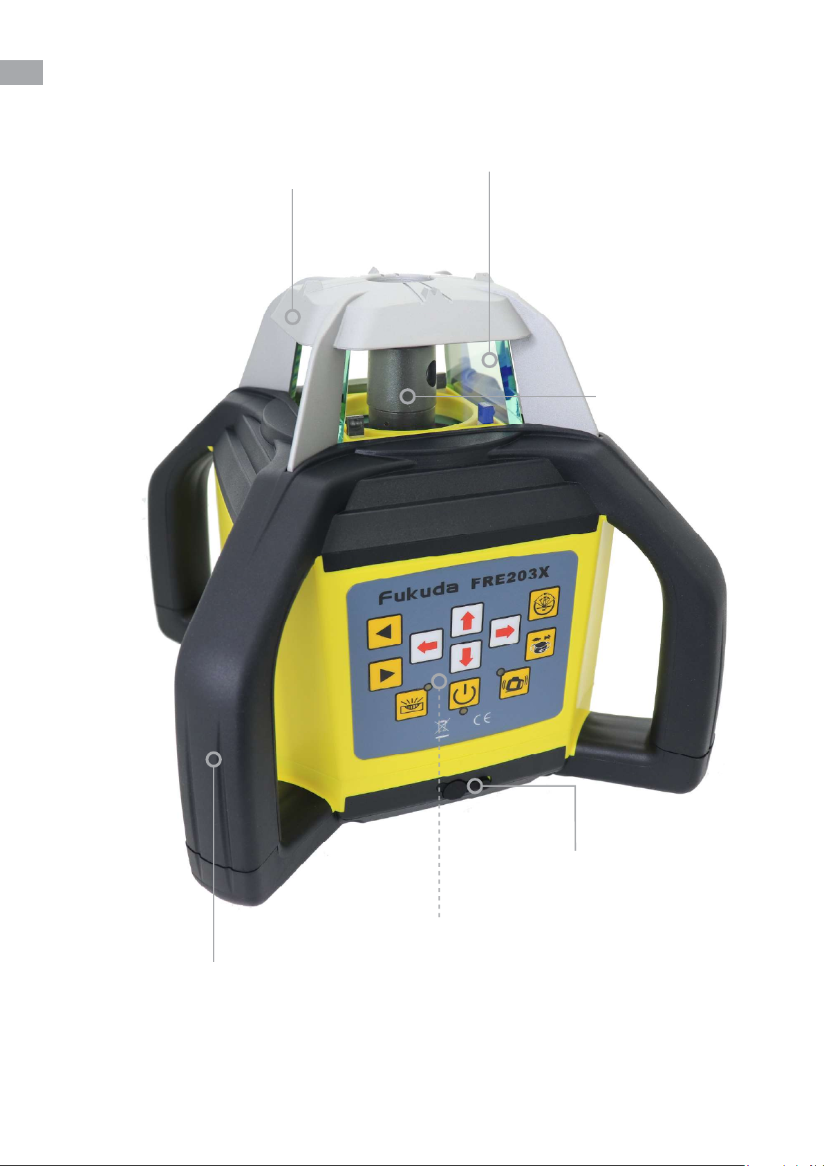
The Fukuda FRE-203XR is accurate, well-featured and competitively priced. It replaces the
extremely reliable Fukuda FRE-301R, to which it shares many of its internal components. It
builds upon this foundation to incorporate many new features and improvements. This is
currently the only model in the Fukuda range which is extremely robust, having a drop-test
specifi cation of 1 metre onto concrete. The top glass “lighthouse” is protected by a metal die-
cast cover whilst a robust roll cage adds increased durability.
It’s a professional laser level kit from the Fukuda Laser Company. They are specialists in their
fi eld of laser level manufacture & certifi ed to ISO-9001.
The FRE-203XR quickly auto levels to set horizontals, verticals and 90-degree site squaring. An
invaluable feature.
In addition, this laser can be switched to Manual mode where the spinning beam can set a
grade (fall) in the X-axis, Y-axis or both together (dual grade). You can only grade match with this
system and not key in a value, however, it will set up to a 1:10 (10%) grade.
Read the following safety instructions before attempting to operate this Laser Level Kit.
Keep these instructions in a safe place or store in the Laser’s carry case for future reference.
- Do not remove warning labels from the product.
- The FRE-203XR is a class 2 laser product (<1 mW; 630 - 685nm)
3
Never look into the laser beam or direct it to the eyes of other people.
Always operate the Laser Level in a way that prevents the beam from
getting into people’s eyes.
Using the FRE-203XR diff erently than described in the user guide, may
result in unsafe operation.

Carry Case
Foam Lined Carry Case
WHAT’S INCLUDED IN THE KIT
The Fukuda FRE-203XR Kit includes the following items. Your contents may vary if the kit
was customised at point-of-purchase to upgrade or remove items.
Fukuda FRE-203XR
Battery Packs & Charger
FRD600R Laser Detector
Red Target & Glasses
RC203X Remote Control
Tripod & Staff
Horizontal, Vertical, 90° Squaring
& Dual Grade
Rechargeable Battery (pre-
installed in base of laser), Spare
Alkaline Battery & UK Charger
Laser Detector / Receiver
With Staff Mounting Clamp
Red Laser Target & Red Laser
Enhancement Glasses
Infrared Remote Control For
Setting Gradients & Slopes
Surveying Tripod &
Measuring Staff
(Colours / Brand may vary)
4

LASER OVERVIEW
5
4 Handle Roll Cage
Rechargeable Battery Charging Port
Protective Lighthouse
Rotating Laser Prism
Die-cast Head
Key Pad (Expanded On Page 7)

LASER OVERVIEW (CONTINUED)
6
Rechargeable Battery Pack
Rechargeable
Battery Charging Port(s)
Battery Lock
(Screw On/Off )
Key Pad (Expanded On Page 7)
5/8” x 11 Thread
For Horizontal
Tripod Mounting
Lay-Down Position Including
5/8” x 11 Mounting Thread
(Located Underneath)

ON/OFF Button
This Button will turn the Laser On and Off .
When turned on, the Laser will auto self level within
15-20 seconds and start spinning a level datum.
No other button needs to be pressed for the
laser to self level.
KEY PAD OVERVIEW
7
Scan Mode
(Stop Dot, 10°, 45°, 90°, 180° Line)
Rotational Speed Control - Tortoise/
Hare. Zero (Stop Dot), 60, 300 &
600rpm
Manual Override
(Disables Self Levelling!)
Move Stop Dot / Scan Line Left
(Scan Mode Must Be Running)
Move Stop Dot / Scan Line Right
(Scan Mode Must Be Running)
Up / Down Arrows
(Grade / Slope Controls)
Right Arrow
(Grade / Slope Control)
Left Arrow
(Grade / Slope Control)
Automatic Drift System (ADS)

REMOTE CONTROL OVERVIEW
8
The Fukuda RC203X Infrared Remote Control enables the user to remotely (up to 20m), adjust
the following settings: Rotational speed, Scan angle & position, Manual Override (for single or
dual-axis grade/slope control). It cannot be used to turn the Laser ON or OFF (a feature not
available on any Fukuda laser level system).
TIP - it is often better to use the Remote Control rather than the FRE-203XR’s keypad, to avoid
disturbing the laser’s sensitive self levelling mechanism.
Scan Mode
(Stop Dot, 10°, 45°, 90°, 180° Line)
Rotational Speed Control - Tortoise/Hare.
Zero (Stop Dot), 60, 300 & 600rpm
Move Stop Dot / Scan Line Right
(Scan Mode Must Be Running)
Up / Down / Left & Right Arrows
(Grade / Slope Controls)
Manual Override
(Disables Self Levelling!)
Move Stop Dot / Scan Line Left
(Scan Mode Must Be Running)
Power Supply & Battery Replacement
●The RC203X remote is powered by 2 x AAA alkaline batteries which will be pre-installed.
●When required, open the rear battery compartment and fi t 2 x AAA alkaline replacement
batteries, taking care to ensure correct polarity.

LASER DETECTOR OVERVIEW
9
The FRE-203XR Kit is available with either the standard FRD600R Detector or the upgraded
FRD800R Detector with mm/inch display. The overview below shows the standard FRD600R.
125mm Reception Pick-up Window
LED Indicators
Detector Sensitivity: Fine, Medium & Course
(+/- 1mm, +/-2.5mm & +/- 5mm)
Front LCD Display Screen
FMB-02 Staff Mounting
Bracket
ON/OFF Button
Sounder (Quiet, Loud & Off ) Back Light (On / Off )
FRONT
Power Supply & Battery Replacement
●The FRD600R Detector is powered by 1 x 9v PP3 alkaline battery which will be pre-installed.
●When required, open the rear battery compartment and fi t 1 x 9v PP3 alkaline replacement
battery, taking care to ensure correct polarity.

LASER DETECTOR OVERVIEW (CONTINUED)
Rear LCD Display Screen
FMB-02 Staff Mounting
Speaker
Battery Compartment
REAR
Using The Detector
●Press the ON/OFF button once and the FRD600R will power on.
●Clamp the Detector onto the front face of the measuring staff and face towards the Laser.
If you are above the horizontal datum, a down arrow will be shown. Below the horizontal
datum an up arrow will be shown and when you are completely level or on the same datum,
a horizontal line will be shown on the display. When you have established the horizontal
datum, you can then use the mm scale on the rear of the measuring staff (which is zero mm
at ground level) to either measure a uniform distance down or a uniform distance up, to then
set your base level, deck level, ground level etc.
10

CHARGING & BATTERIES
11
The FRE-203XR is supplied with a Fukuda 4.8V Ni-MH Rechargeable Battery, a Fukuda 6V
Alkaline Battery (Non-rechargeable) and a 5.6 Volt UK Plug, 900mA charger. Typically only the
rechargeable battery pack is used, with the alkaline battery pack being used as a back-up power
source.
Rechargeable Battery Pack
The 5.6 Volt UK Plug, 900mA charger (Input 100-240V AC 50/60Hz. Output DC 5.6V 900mA,
centre pin + polarity) is for indoor use only. If the charger becomes damaged, stop using
immediately and purchase a replacement. Never use a generic charger with this laser.
●Prior to fi rst use, we recommend that you fully charge the battery pack for around 7-8 hours.
●The battery pack contains 4 x “sealed for life” Ni-MH type C, 4000mAh, 1.2V cells. Please note
that this battery pack can be charged either in or outside of the laser.
●Important: Do NOT allow battery to go completely fl at before recharging.
Mains Charger
●The general procedure to adopt is use the laser during the day & charge-up overnight. You
cannot damage the system by “over-charging” the batteries.
●When the charger is plugged into a 230V mains supply (but not connected to the Laser), the
red LED on the charger will fl ash once per second, when operating correctly.
●Plug the charger into the charging port located on the battery pack or underneath the control
panel on the front face of the laser. Both allow the battery to charge.
●When charging, the red LED on the charger will stop fl ashing and be illuminated
continuously.
●The LED will change to green when there is suffi cient charge in the battery.
●The FRE-203XR can be operated with the charger connected to the mains supply, if required
and is approved on site.
●The Mains Charger will charge most batteries in around 7 hours to give approximately 50
hours of continuous use. It takes 4 to 5 charge/discharge cycles for these battery packs to
reach their maximum capacity.
Alkaline Battery Pack (Non-rechargeable)
●The Alkaline Battery Pack is designed to be a backup power source if the main rechargeable
battery has not been charged.
●The battery pack contains 4 x type C, 1.5V alkaline batteries. These are readily available from
all good hardware stores / supermarkets.
●Important: Do NOT attempt to recharge this battery, otherwise serious damage will occur.

INSTRUCTIONS
12
Position Laser
Pick Up The Levels
Place the FRE-203XR on a fi rm, generally level surface
or screw onto the 5/8” thread of the surveying tripod.
You do not need to independently level the surface or
tripod, but is does need to be within ±5 deg of true horizontal.
1.
3.
Horizontal Levelling
Power On
Read The Levels
Press the ON/OFF button once and the FRE-203XR
will power on and begin automatically self-levelling horizontally.
This process takes around 15-20 seconds.
When the levelling process is complete, the laser beam will start
spinning at 600rpm, indicating a level datum.
No other button needs to be pressed for the laser to self level.
When you have established the horizontal datum, you can then
use the mm scale on the rear of the measuring staff (which is
zero mm at ground level) to either measure a uniform distance
down or a uniform distance up, to then set your base level, deck
level, ground level etc.
2.
4.
Clamp the Detector onto the front face of the measuring staff and
face towards the Laser. If you are above the horizontal datum, a
down arrow will be shown. Below the horizontal datum an up
arrow will be shown and when you are completely level or on the
same datum, a horizontal line will be shown on the display.
There is also a corresponding audible tone and LED indicators.
WARNING
Never operate Laser in front of
glazing or any shiny surfaces!
See page 25 for further details.

INSTRUCTIONS
13
Position Laser
Pick Up The Vertical
Place the the FRE-203XR on the rear lay-down mount
on a fi rm, generally level surface. The mount is located on the
opposing side of the keypad.
You do not need to independently level the surface but is does
need to be within ±5 deg of true horizontal.
1.
3.
Vertical Levelling
Power On
Press the ON/OFF button once and the FRE-203XR
will power on and begin automatically self-levelling vertically.
This process takes around 15-20 seconds.
When the levelling process is complete, the laser will start
spinning at 600rpm, indicating a vertically level datum.
No other button needs to be pressed for the laser to self level.
2.
Turn the Detector onto it’s side (landscape mode) and face
towards the Laser. The up and down arrows used for horizontal
levelling will then become left and right arrows. The Detector will
accurately pinpoint the vertical datum and the arrows on screen
will indicate which direction to go. When in alignment, it will
display a vertical black line. You can then walk forward of your
position continually marking the datum. This method can be
used instead of a string line or to align a datum on the vertical. e.g. I-section steels, fence posts, timber
frame structures, racking etc.
WARNING
Never operate Laser in front of
glazing or any shiny surfaces!
See page 25 for further details.

INSTRUCTIONS
14
Position Laser & Power On
Pick Up The Vertical
Take the FRE-203XR off the tripod and lay on a fi rm surface, at
ground level on the rear lay-down mount. The mount is located
on the opposing side of the keypad. The laser should be placed
over your intended corner point. Then press the ON/OFF button
once to turn on the level and wait for the laser to self-level before
pressing the manual override button once.
1.
2.
90° Squaring
Pick Up The Laser Dot
The second part of the 90° is achieved by marking the position of
the red laser dot that is fi red from the centre of the lighthouse.
The laser dot cannot be picked up with your detector.
You need a target plate. Our recommendation is to use a
small piece of around 300mm long white contiplas board,
6-9” wide or similar. Using a black marker pen, draw a
vertical line down the middle of the board. The white
3.
With the Laser prism now spinning (like the wheel of a car), turn
the Detector onto it’s side (landscape mode) and face towards
the Laser. The up and down arrows used for horizontal
levelling will then become left and right arrows. The Detector
will accurately pinpoint the vertical datum and the arrows on
screen will indicate which direction to go. When in alignment it
will display a vertical black line. You can then walk up to 250m
forward of your position continually marking the datum. When this is complete, you will have marked out
the fi rst part of the 90° and you can now return to the laser to begin setting out the second part.
surface is an ideal target to “pick-up” the red dot at distance, even in bright sunlight. Hold the
end face of the target board down onto the ground, align the dot onto the black line and mark
the position accordingly at appropriate intervals. This has set 90 degree squaring. If you had
an aerial or top down view, you would see a perfectly set out “L” shape or corner without using a
Set Square or 3/4/5 Triangle calculation.
User Tip
Please see page 23 for a more in depth guide to 90° Squaring.
WARNING
Never operate Laser in front of
glazing or any shiny surfaces!
See page 25 for further details.

USING THE LASER
15
Power On
●Press the ON/OFF button once and the FRE-203XR will power on and begin
automatically self-levelling. This process takes around 15-20 seconds. When the
levelling process is complete, the laser will start spinning at 600rpm, indicating
a level datum.
Power Off
●Press the OFF button once and the FRE-203XR will power off .
●If the Laser has been put into grade mode, scan or the rotational speed set
at zero, switching off the laser and turning it back on again will automatically
return the laser to the default fully self levelled state, running at 600rpm.
Rotational Speed Control - Tortoise/Hare
●Press the Rotational Speed Control button on the face of the laser or on the
remote to cycle through the 4 rotational speeds.
●The rotational speeds are Zero (Stop Dot), 60rpm, 300rpm & 600rpm.
●For Indoor work, we suggest using slower speeds, where the laser beam is
easier to see by eye; but for Outdoor Groundworks – run the FRE-203XR at its
maximum speed of 600rpm; which gives the best working range when used
with the supplied Laser Detector.
●The default rotational mode is 600rpm when the laser self levels after being
turned on.
Scan Mode
●Press the Scan Mode button on the face of the laser or on the remote to cycle
through the 5 scan modes. Each mode adjusts the angle of the beam.
●The scan modes allows the user to set a Stop Dot, 10°, 45°, 90°, 180° Line.
●The scan mode is typically only used indoors and enables the user to see the
beam better in a specifi c position.
●The Detector cannot pickup the Laser beam when in scan mode.
●Pressing the Rotational Speed Control button once will turn off scan mode and
return the laser to rotating at 600rpm.

USING THE LASER (CONTINUED)
16
Manual Override
●Press the Manual Override button on the face of the laser or on the remote
once and the self levelling system will be turned off . The Laser will continue to
rotate but the laser will no longer be outputting a level datum.
●This mode is typically enabled when the laser is being used to do Gradients and
Slopes (See Gradients & Slopes section on page 18 for further details).
●Pressing the Manual Override button once more will turn the self levelling
system back on. The Laser head will stop and adjust to a level datum and then
begin rotating at 600rpm. The laser is now running in self levelling mode once
more.
Up / Down / Left & Right Arrows
●When the FRE-203XR is in manual mode (Self levelling system has been turned
off ), the Up / Down / Left & Right arrows are used to tilt the laser prism in either
the X or Y axis to set a progressive fall or gradient. (See Gradients & Slopes
section on page 18 for further details).
Automatic Drift System (ADS)
●If the FRE-203XR is running in self levelling mode, press the Automatic Drift
System (ADS) button on the face of the laser to turn on the Automatic Drift
System.
●Once activated the green LED will fl ash slowly. ADS is now ON.
●If for example, the FRE-203XR is knocked or caught by a gust of wind, the laser
prism will stop rotating and the green ADS LED will fl ash quickly to show an
alarm condition. Check that your datums have not altered and if all is ok; press
the ADS button again & the laser will reset to AUTO level. This function is used
to alert users that the laser has been disturbed. If this mode has not been
turned on and the laser is disturbed, it is possible that although a level datum
will be continue to be produced it may be at a diff erent height than before.
●The ADS function cannot be activated when in manual mode doing Gradients
or Slopes.
Rotate Stop Dot / Scan Line (Left or Right)
●When the FRE-203XR is in Scan mode or set at 0rpm, the Rotate Stop Dot / Scan
Line Left and Right buttons can be pressed to rotate the position of the laser
prism either clockwise or counter clockwise.
●This is useful to position the stop dot or line on a specifi c point in the room.

USING THE LASER (CONTINUED 2)
17
Grading
●The FRE-203XR is a DUAL GRADE facility laser level. This means that the FRE-203XR can be
switched to “Manual” (to override the self levelling system) allowing the user to set a grade
(incline/slope) in the X axis only, Y axis only or both together. The maximum settable slope is
an approx. fall of 1m over 10m.
●For X & Y alignment, please see the case markings on the TOP of the laser head where sights
point in the direction of the axis being set.
Setting Single Axis Slope
●This example sets a grade in the X axis.
●Press the ON/OFF button once and the FRE-203XR will power on and begin automatically self-
levelling.
●Press the Manual Override button on the face of the laser or on the remote once and the self
levelling system will be turned off & the green LED illuminates.
●Using the red Left & Right Arrow buttons on either the face of the laser or on the remote,
set the % slope (fall) required - as measured on your staff .
●When complete, press the Manual Override button once more and this will turn the self
levelling system back on. The Laser head will stop and adjust to a level datum and then begin
rotating at 600rpm. The laser is now running in self levelling mode once more.
Setting Y Axis Slope
●This example sets a grade in the Y axis.
●Press the ON/OFF button once and the FRE-203XR will power on and begin automatically self-
levelling.
●Press the Manual Override button on the face of the laser or on the remote once and the self
levelling system will be turned off & the green LED illuminates.
●Using the red Up & Down Arrow buttons on either the face of the laser or on the remote, set
the % slope (fall) required - as measured on your staff .
●When complete, press the Manual Override button once more and this will turn the self
levelling system back on. The Laser head will stop and adjust to a level datum and then begin
rotating at 600rpm. The laser is now running in self levelling mode once more.
Setting Both X & Y Axis Slopes (Dual Grade)
●Proceed as above, but use all four red Arrow buttons - as required.

HOW TO SET SLOPES (FALLS/GRADES)
18
Working Example 1
The following description in this guide, explains the general principles of setting a Slope (Fall/
Grade) when using the FRE-203XR.
Equipment
You will need the FRE-203XR laser level, a surveying tripod, measuring staff (rod) with mm scale
and a laser detector/receiver. Its not essential but having the remote control for the laser level is
preferable. (Without a remote control, having another person to assist you, is essential).
Site Conditions
There are many diff erent work site scenarios. As an example, we are assuming that you are
outside on a site with a clear fi eld of view and planning to set drainage falls.
All above ground and below ground drainage pipes should be laid to an adequate gradient. The
fall in a pipe is defi ned as the vertical height by which the pipe drops over a known distance. e.g.
a 2.5% gradient is a fall of 1m over 40m or 1:40. (1 in 40).
Typically, surface water or foul water drainage pipes are set between 1:40 to 1:80.
If a gradient is too steep i.e. steeper than 1 in 40, the liquid may run faster than the solids in a
foul water pipe thus leaving the solids stranded, which could then block the pipe. Conversely,
if a gradient is not steep enough (usually less than 1 in 110), then the pipe may still block, if the
solids slow down and become stranded.
Procedure
Place the FRE-203XR horizontally on the surveying tripod, switch it ON and allow it to auto (self)
level. Note the X-axis / Y-axis markings on the top cover of the laser.
Setting a 1:40 gradient: Position the measuring staff at 10m away from the tripod, held
vertically and move the laser detector (receiver) along the staff to fi nd the set level position,
usually by giving a continuous audible tone. By proportion, a 1m fall at 40m is only 250mm
at 10m, so carefully noting the set level dimension on the rear of the staff , move the detector
down by 250mm and clamp tight.
Using the remote control (from the staff location) or a colleague at the laser, press the Manual
Override button and have the axis to be adjusted facing the measuring staff .
Hold the “down arrow” button on the remote control or laser’s keypad, to slope the laser beam
down the measuring staff until it gives a continuous tone again, having found set level on the
detector. This has now set a 1:40 fall.
Return the laser detector to the original set level dimension on the staff .
Dig out ground & lower staff until the laser detector picks up the laser beam again.
Important note: All “grade facility” rotary lasers revert back to the auto (self) level condition if
switched Off without retaining the gradient set. So its recommended to complete the ground-
works before switching the laser Off .

HOW TO SET SLOPES (FALLS/GRADES)
19
Working Example 1 (Continued)
Once this 1:40 fall is set, the User can use this inclined laser beam as a datum to set the depth of
either the crown of the drainage pipe or the Invert level, anywhere in range of the laser – along
that same axis.
Invert level of a pipe – is the level taken from the bottom of the inside of the pipe.
Crown of a pipe – is the Invert level plus the internal diameter of the pipe plus the pipe wall
thickness. It may be necessary to use this in calculations when level measurements are taken
from the crown of a pipe.
Manhole / Access Chambers:
A manhole or access chamber is required to gain access to a drainage system for un-blocking,
cleaning, rodding or inspection. (Land drainage systems excluded). They can be manufactured in
PVC, masonry or pre-cast concrete.
When setting appropriate drainage gradients it is important to allow for the depth down to
either the crown of the pipe (or the Invert level) from ground level, when using these manholes.
Dual Grading:
A rotary laser level with dual grading facility can be used for setting out driveways, car-parks or
areas with slopes (falls) in BOTH the X & Y axis.
The same procedure is adopted as above for drainage runs, except a second step in the process
is undertaken to set the laser to a fall in the other axis, to complete the dual grade setting-out.
Cut & Fill Machine control work:
If slopes of more than 10% (1:10) are required, which is outside the range of electronic
adjustment of the rotary laser’s prism; then simply switch the laser to Manual & fi t a “Laser
Grade Adapter” between the top face of the tripod & the base of the laser. Then set the required
slope. Search our website for more details.

20
HOW TO SET SLOPES (FALLS/GRADES)
Working Example 2 (when you do NOT know the grade to set)
Diagram 1
Diagram 2
Diagram 3
Use diagrams in conjunction with
written example on page 21.
Other manuals for FRE-203XR
1
Table of contents
Other Fukuda Laser Level manuals

Fukuda
Fukuda FLG-411QG User manual

Fukuda
Fukuda EK-226P User manual

Fukuda
Fukuda FRE-205 User manual

Fukuda
Fukuda FDG-232R User manual

Fukuda
Fukuda EK-268G User manual

Fukuda
Fukuda FRE-102AG User manual

Fukuda
Fukuda FRE-207 User manual

Fukuda
Fukuda FRE-301R User manual

Fukuda
Fukuda FRE-208 User manual

Fukuda
Fukuda FRE-203XR User manual