Fukuda FRE-203XT User manual

Laser Levels Online
Fukuda FRE-203XT
REVISION 1.0
User Guide
© 2021 Laser Levels Online
TRUE Grade

KEY INFORMATION
2
Specifi cation
Brand Fukuda
Product Type Rotating Laser Level
Levelling Type Fully Self Levelling
Detector Range Up to 500m Diameter (250m either side of Laser)
Accuracy ±2.8mm at 30m (100ft)
Beam Colour Red Beam
Beam Type Rotating Dot
Levelling Axis Horizontal & Vertical Levelling
Facilities 90° Squaring, Scan, Plumb (Up), Plumb (Down)
Usage Indoor & Outdoor
Battery Rechargeable Battery Pack or use Alkaline Batteries
Runtime Up to 20 Hours (Approx)
Slope / Gradient Dual Grade using Keypad or included Remote Control
Mounting Thread ⅝” Standard Surveying
Laser Rating Class 2
Durability Excellent
IP Rating IP66 - Dust tight / Protected against powerful jets of water
Warranty Automatic 3 Year Warranty

INTRODUCTION
Overview
SAFETY
WARNING
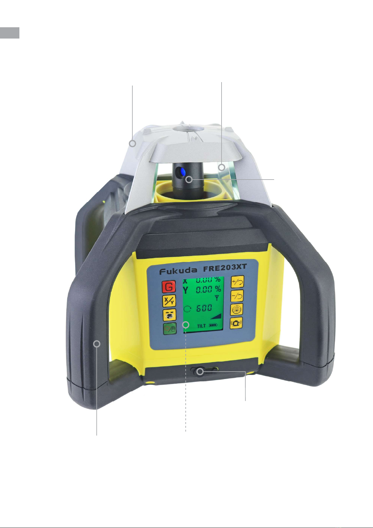
Thank you for purchasing the Fukuda FRE-203XT True Grade rotary laser kit.
These instructions are intended to explain the general basics of operating this equipment.
Please read them carefully.
For any more information, or if the laser requires calibration or repair; then please contact our
Service Department by Telephone: 08000 869 769 or Email: [email protected]
The Fukuda FRE-203XT replaces the extremely reliable outgoing Fukuda FRE-208 True Grade
laser, to which it shares many of its internal components. It builds upon this foundation to
incorporate many new features and improvements which it shares with the other FRE-203X
series lasers.
The FRE-203XT is a TRUE GRADE laser where the user can easily input the exact % of slope
required. The instrument will then simply set the laser beam to that slope. This can be in one
axis only (single grade) or in two axis X & Y together for dual grading. A radio linked Remote
Control with a 100m range makes this quick & easy.
The laser also has plumb up & plumb down, red laser dot beams. By mounting the instrument
on its side, called “lay-down” this gives a squaring facility. i.e. 90-degree site setting out - a very
useful feature.
Constructed with a waterproof housing, an automatic drift system and the facility of radio
controlled Dual grade - has made this the Grade laser of choice for Groundworks Contractors.
This is another model in the Fukuda range which is extremely robust, having a drop-test
specifi cation of 1 metre onto concrete. The top glass “lighthouse” is protected by a metal die cast
cover, whilst a robust roll cage adds increased durability.
The FRE-203XT is also suitable for indoor use, where the rotating speed can be reduced to
improve visibility of the laser beam by eye; together with a concentrated beam, SCAN facility.
Read the following safety instructions before attempting to operate this Laser Level Kit.
Keep these instructions in a safe place or store in the Laser’s carry case for future reference.
- Do not remove warning labels from the product.
- The FRE-203XT is a class 2 laser product (<1 mW; 630 - 685nm)
3
Never look into the laser beam or direct it to the eyes of other people.
Always operate the Laser Level in a way that prevents the beam from
getting into people’s eyes.
Using the FRE-203XT diff erently than described in the user guide, may
result in unsafe operation.

Carry Case
Foam Lined Carry Case
WHAT’S INCLUDED IN THE KIT
The Fukuda FRE-203XT Kit includes the following items. Your contents may vary if the kit
was customised at point-of-purchase to upgrade or remove items.
Fukuda FRE-203XT
Battery Packs & Charger
FRD600R Laser Detector
Red Target & Glasses
RC203XT Remote Control
Tripod & Staff
Horizontal, Vertical, 90° Squaring
& TRUE Grade (X & Y)
Rechargeable Battery (pre-
installed in base of laser), Spare
Alkaline Battery & UK Charger
Laser Detector / Receiver
With Staff Mounting Clamp
Red Laser Target & Red Laser
Enhancement Glasses
Radio remote Control For
Setting Gradients & Slopes
Surveying Tripod &
Measuring Staff
(Colours / Brand may vary)
4

LASER OVERVIEW
5
4 Handle Roll Cage
Rechargeable Battery Charging Port
Protective Lighthouse
Rotating Laser Prism
Die-cast Head
Key Pad (Expanded On Page 7)

LASER OVERVIEW (CONTINUED)
6
Rechargeable Battery Pack
Rechargeable
Battery Charging Port(s)
Battery Lock
(Screw On/Off )
Key Pad (Expanded On Page 7)
5/8” x 11 Thread
For Horizontal
Tripod Mounting
Lay-Down Position Including
5/8” x 11 Mounting Thread
(Located Underneath)

ON/OFF Button & Manual Override
This Button will turn the Laser On and Off .
When turned on, the Laser will auto self level within 15-20
seconds and start spinning a level datum.
Holding the button for 5 seconds will start the laser,
with the self levelling mechanism turned OFF.
X & Y Axis Selector
(Grade / Slope Controls)
KEY PAD OVERVIEW
7
Automatic Drift System (ADS)
True Grade Mode
Rotational Speed Control - Tortoise/Hare.
Zero (Stop Dot), 60, 120, 300 & 600rpm
Increase Slope Angle
(Grade / Slope Controls)
& Move Stop Dot / Scan
Line Right (Scan Mode
Must Be Running)
Scan Mode
(Stop Dot, 10°, 45°, 90°,
180° Line)
Decrease Slope Angle (Grade / Slope Controls)
& Move Stop Dot / Scan Line Left (Scan Mode
Must Be Running)

X & Y Axis Selector
(Grade / Slope Controls)
Decrease Slope Angle
(Grade / Slope Controls)
Increase Slope Angle
(Grade / Slope Controls)
REMOTE CONTROL OVERVIEW
8
The Fukuda FRE-203XT Radio Remote Control enables the user to remotely (up to 100m), adjust
the following settings: Rotational speed, Scan angle & position as well as inputting a gradient
or slope as a %. It cannot be used to turn the Laser ON or OFF (a feature not available on any
Fukuda laser level system).
TIP - it is often better to use the Remote Control rather than the FRE-203XT’s keypad, to avoid
disturbing the laser’s sensitive self levelling mechanism.
Scan Mode
(Stop Dot, 10°, 45°, 90°,
180° Line)
Rotational Speed Control
- Tortoise/Hare. Zero
(Stop Dot), 60, 120, 300
& 600rpm
Move Stop Dot / Scan Line Right
(Scan Mode Must Be Running)
Display
Move Stop Dot / Scan Line Left
(Scan Mode Must Be Running)
Power Supply & Battery Replacement
●The FRE-203XT remote is powered by 2 x AAA alkaline batteries which will be pre-installed.
●When required, open the rear battery compartment and fi t 2 x AAA alkaline replacement
batteries, taking care to ensure correct polarity.
ON/OFF Button
(Turns Remote on/off only)
True Grade Mode

LASER DETECTOR OVERVIEW
9
The FRE-203XT Kit is available with either the standard FRD600R Detector or the upgraded
FRD800R Detector with mm/inch display. The overview below shows the standard FRD600R.
125mm Reception Pick-up Window
LED Indicators
Detector Sensitivity: Fine, Medium & Course
(+/- 1mm, +/- 2.5mm & +/- 5mm)
Front LCD Display Screen
FMB-02 Staff Mounting
Bracket
ON/OFF Button
Sounder (Quiet, Loud & Off ) Back Light (On / Off )
FRONT
Power Supply & Battery Replacement
●The FRD600R Detector is powered by 1 x 9v PP3 alkaline battery which will be pre-installed.
●When required, open the rear battery compartment and fi t 1 x 9v PP3 alkaline replacement
battery, taking care to ensure correct polarity.

LASER DETECTOR OVERVIEW (CONTINUED)
Rear LCD Display Screen
FMB-02 Staff Mounting
Speaker
Battery Compartment
REAR
Using The Detector
●Press the ON/OFF button once and the FRD600R will power on.
●Clamp the Detector onto the front face of the measuring staff and face towards the Laser.
If you are above the horizontal datum, a down arrow will be shown. Below the horizontal
datum an up arrow will be shown and when you are completely level or on the same datum,
a horizontal line will be shown on the display. When you have established the horizontal
datum, you can then use the mm scale on the rear of the measuring staff (which is zero mm
at ground level) to either measure a uniform distance down or a uniform distance up, to then
set your base level, deck level, ground level etc.
10

CHARGING & BATTERIES
11
The FRE-203XT is supplied with a Fukuda 4.8V Ni-MH Rechargeable Battery, a Fukuda 6V
Alkaline Battery (Non-rechargeable) and a 5.6 Volt UK Plug, 900mA charger. Typically only the
rechargeable battery pack is used, with the alkaline battery pack being used as a back-up power
source.
Rechargeable Battery Pack
The 5.6 Volt UK Plug, 900mA charger (Input 100-240V AC 50/60Hz. Output DC 5.6V 900mA,
centre pin + polarity) is for indoor use only. If the charger becomes damaged, stop using
immediately and purchase a replacement. Never use a generic charger with this laser.
●Prior to fi rst use, we recommend that you fully charge the battery pack for around 7-8 hours.
●The battery pack contains 4 x “sealed for life” Ni-MH type C, 4000mAh, 1.2V cells. Please note
that this battery pack can be charged either in or outside of the laser.
●Important: Do NOT allow battery to go completely fl at before recharging.
Mains Charger
●The general procedure to adopt is use the laser during the day & charge-up overnight. You
cannot damage the system by “over-charging” the batteries.
●When the charger is plugged into a 230V mains supply (but not connected to the Laser), the
red LED on the charger will fl ash once per second, when operating correctly.
●Plug the charger into the charging port located on the battery pack or underneath the control
panel on the front face of the laser. Both allow the battery to charge.
●When charging, the red LED on the charger will stop fl ashing and be illuminated
continuously.
●The LED will change to green when there is suffi cient charge in the battery.
●The FRE-203XT can be operated with the charger connected to the mains supply, if required
and is approved on site.
●The Mains Charger will charge most batteries in around 7 hours to give approximately 20
hours of continuous use. It takes 4 to 5 charge/discharge cycles for these battery packs to
reach their maximum capacity.
Alkaline Battery Pack (Non-rechargeable)
●The Alkaline Battery Pack is designed to be a backup power source if the main rechargeable
battery has not been charged.
●The battery pack contains 4 x type C, 1.5V alkaline batteries. These are readily available from
all good hardware stores / supermarkets.
●Important: Do NOT attempt to recharge this battery, otherwise serious damage will occur.

INSTRUCTIONS
12
Position Laser
Pick Up The Levels
Place the FRE-203XT on a fi rm, generally level surface
or screw onto the 5/8” thread of the surveying tripod.
You do not need to independently level the surface or
tripod, but is does need to be within ±5 deg of true horizontal.
1.
3.
Horizontal Levelling
Power On
Read The Levels
Press the ON/OFF button once and the FRE-203XT
will power on and begin automatically self-levelling horizontally.
This process takes around 15-20 seconds.
When the levelling process is complete, the laser beam will start
spinning at 600rpm, indicating a level datum.
No other button needs to be pressed for the laser to self level.
When you have established the horizontal datum, you can then
use the mm scale on the rear of the measuring staff (which is
zero mm at ground level) to either measure a uniform distance
down or a uniform distance up, to then set your base level, deck
level, ground level etc.
2.
4.
Clamp the Detector onto the front face of the measuring staff and
face towards the Laser. If you are above the horizontal datum, a
down arrow will be shown. Below the horizontal datum an up
arrow will be shown and when you are completely level or on the
same datum, a horizontal line will be shown on the display.
There is also a corresponding audible tone and LED indicators.
WARNING
Never operate Laser in front of
glazing or any shiny surfaces!
See page 29 for further details.

INSTRUCTIONS
13
Position Laser
Pick Up The Vertical
Place the the FRE-203XT on the rear lay-down mount
on a fi rm, generally level surface. The mount is located on the
opposing side of the keypad.
You do not need to independently level the surface but is does
need to be within ±5 deg of true horizontal.
1.
3.
Vertical Levelling
Power On
Press the ON/OFF button once and the FRE-203XT
will power on and begin automatically self-levelling vertically.
This process takes around 15-20 seconds.
When the levelling process is complete, the laser will start
spinning at 600rpm, indicating a vertically level datum.
No other button needs to be pressed for the laser to self level.
2.
Turn the Detector onto it’s side (landscape mode) and face
towards the Laser. The up and down arrows used for horizontal
levelling will then become left and right arrows. The Detector will
accurately pinpoint the vertical datum and the arrows on screen
will indicate which direction to go. When in alignment, it will
display a vertical black line. You can then walk forward of your
position continually marking the datum. This method can be
used instead of a string line or to align a datum on the vertical. e.g. I-section steels, fence posts, timber
frame structures, racking etc.
WARNING
Never operate Laser in front of
glazing or any shiny surfaces!
See page 29 for further details.

INSTRUCTIONS
14
Position Laser & Power On
Pick Up The Vertical
Take the FRE-203XT off the tripod and lay on a fi rm surface, at
ground level on the rear lay-down mount. The mount is located
on the opposing side of the keypad. The laser should be placed
over your intended corner point. Then press the ON/OFF button
once to turn on the level and wait for the laser to self-level before
pressing holding the ON/OFF button for 5 seconds until the
“hand” is shown on the display.
1.
2.
90° Squaring
Pick Up The Laser Dot
The second part of the 90° is achieved by marking the position of
the red laser dot that is fi red from the centre of the lighthouse.
The laser dot cannot be picked up with your detector.
You need a target plate. Our recommendation is to use a
small piece of around 300mm long white contiplas board,
6-9” wide or similar. Using a black marker pen, draw a
vertical line down the middle of the board. The white
3.
With the Laser prism now spinning (like the wheel of a car), turn
the Detector onto it’s side (landscape mode) and face towards
the Laser. The up and down arrows used for horizontal
levelling will then become left and right arrows. The Detector
will accurately pinpoint the vertical datum and the arrows on
screen will indicate which direction to go. When in alignment it
will display a vertical black line. You can then walk up to 250m
forward of your position continually marking the datum. When this is complete, you will have marked out
the fi rst part of the 90° and you can now return to the laser to begin setting out the second part.
surface is an ideal target to “pick-up” the red dot at distance, even in bright sunlight. Hold the
end face of the target board down onto the ground, align the dot onto the black line and mark
the position accordingly at appropriate intervals. This has set 90 degree squaring. If you had
an aerial or top down view, you would see a perfectly set out “L” shape or corner without using a
Set Square or 3/4/5 Triangle calculation.
User Tip
Please see page 27 for a more in depth guide to 90° Squaring.
WARNING
Never operate Laser in front of
glazing or any shiny surfaces!
See page 29 for further details.

USING THE LASER
15
Power On
●Press the ON/OFF button once and the FRE-203XT will power on and begin
automatically self-levelling. This process takes around 15-20 seconds.
When the levelling process is complete, the laser will start spinning at
600rpm, indicating a level datum.
●No other button needs to be pressed for the laser to self level.
Power Off
●Press the OFF button once and the FRE-203XT will power off .
●If the Laser has been put into grade mode, scan or the rotational speed
set at zero, switching off the laser and turning it back on again will
automatically return the laser to the default fully self levelled state,
running at 600rpm.
Rotational Speed Control - Tortoise/Hare
●Press the Rotational Speed Control button on the face of the laser or on
the remote to cycle through the 5 rotational speeds.
●The rotational speeds are Zero (Stop Dot), 60rpm, 120rpm, 300rpm &
600rpm.
●For Indoor work, we suggest using slower speeds, where the laser beam is
easier to see by eye; but for Outdoor Groundworks – run the FRE-203XT at
its maximum speed of 600rpm; which gives the best working range when
used with the supplied Laser Detector.
●The default rotational mode is 600rpm when the laser self levels after
being turned on.
Scan Mode
●Press the Scan Mode button on the face of the laser or on the remote to
cycle through the 5 scan modes. Each mode adjusts the angle of the beam.
●The scan modes allows the user to set a Stop Dot, 10°, 45°, 90°, 180° Line.
●The scan mode is typically only used indoors and enables the user to see
the beam better in a specifi c position.
●The Detector cannot pickup the Laser beam when in scan mode.
●Pressing the Rotational Speed Control button once will turn off scan mode
and return the laser to rotating at 600rpm.

USING THE LASER (CONTINUED)
16
Manual Override (Hand Symbol)
●Press and hold the ON/OFF button for 5 seconds until the “Hand” is shown
on the display. When the hand is displayed the self levelling system will be
turned off . The Laser will continue to rotate but the laser will no longer be
outputting a level datum.
●This mode is typically enabled when the laser is being used to do MANUAL
Gradients and Slopes (See X & Y Axis Selector on page 17) or when you
want to manually adjust the squaring feature to align with an existing
datum.
●Pressing and holding the ON/OFF button for 2 seconds until the “hand” is no
longer shown on the display will turn the self levelling system back on. The
Laser head will stop and adjust to a level datum and then begin rotating at
600rpm. The laser is now running in self levelling mode once more.
Increase Slope Angle & Move Stop Dot / Scan Line Right - Dual function button
●When the FRE-203XT is in Scan mode or set at 0rpm, the Rotate Stop Dot
/ Scan Line Right button can be pressed to rotate the position of the laser
prism either clockwise.
●This is useful to position the stop dot or line on a specifi c point in the
room.
●This button is also used to Increase Slope Angle in True Grade & Manual
mode.
Decrease Slope Angle & Move Stop Dot / Scan Line Left - Dual function button
●When the FRE-203XT is in Scan mode or set at 0rpm, the Rotate Stop Dot
/ Scan Line Left button can be pressed to rotate the position of the laser
prism counter clockwise.
●This is useful to position the stop dot or line on a specifi c point in the
room.
●This button is also used to Decrease Slope Angle in True Grade & Manual
mode.

Automatic Drift System (ADS)
●If the FRE-203XT is running in self levelling mode, press the Automatic Drift
System (ADS) button on the face of the laser to turn on the Automatic Drift
System.
●Once activated “TILT” will be shown on the display. ADS is now ON.
●If for example, the FRE-203XT is knocked or caught by a gust of wind, the
laser prism will stop rotating, the spirit level bubble icon will start fl ashing
and a warning triangle will be displayed to show an alarm condition.
There will also be an audible warning. Check that your datums have not
altered and if all is ok; press the ADS button again & the laser will reset to
AUTO level. You will then need to press ADS again to turn ADS back on.
This function is used to alert users that the laser has been disturbed. If
this mode has not been turned on and the laser is disturbed, it is possible
that although a level datum will be continue to be produced it may be at a
diff erent height than before.
●The ADS function can be activated in TRUE grade mode but not when
setting Manual grades or slopes.
USING THE LASER (CONTINUED 2)
17
X & Y Axis Selector
●When the laser is in Manual Override mode, press the X & Y Axis Selector
button and “X” will be shown on the display.
●Pressing either the Increase Slope Angle or Decrease Slope Angle button(s)
will now adjust the position of the laser beam in the X axis only.
●To change to the Y axis, press the X & Y Axis Selector button again and “Y”
will now be shown on the display.
●Pressing either the Increase Slope Angle or Decrease Slope Angle button(s)
will now adjust the position of the laser beam in the Y axis only.
●If the laser is in “lay down” and you are doing 90 degree squaring, ensure
the Axis selector is set on “X” and then use the Plus or Minus buttons to
align the laser with an existing datum.
In combination with:

TRUE Grade Mode
●Press the red “G” button once and the FRE-203XT will enter “True Grade”
mode.
●The X axis indicator will begin fl ashing to indicate it is ready for a % to be
input into the X axis.
●Please see page 23 for the Gradient Conversion Chart.
●Using the keypad or remote control, press either the Increase / Decrease
Slope Angle button until the desired % is displayed on screen.
●When complete, press the X & Y Axis Selector button once and repeat the
process to enter a % in the Y axis. If you only want to enter a value in the X
axis simply leave Y set at 0.00%.
●To fi nally confi rm the % entered in either the X, Y or both axis, press the X
& Y Axis Selector button once more.
●The laser prism will then tilt to the correct angle and then begin rotating at
600rpm.
●To return to Auto level, the red “G” button once. The laser prism will stop
rotating and will then adjust to true level. It will then automatically restart
rotating, auto levelled.
USING THE LASER (CONTINUED 3)
18
In combination with:
X & Y Axis Selector
True Grade Mode Increase Slope Angle
Decrease Slope Angle

USING THE LASER (CONTINUED 4)
19
True Grading
●The FRE-203XT is a TRUE DUAL GRADE laser level. This means that the laser can be switched
to “Manual” (red “G” button to over-ride the level sensors) and then it is very easy for the
User to set a slope (fall/grade) in the X axis only, Y axis only or both together.
●The maximum single slope range is +/- 10.00% ie. 1:10.
●For X & Y axis alignment, please see the markings on the TOP COVER of the laser.
Setting Single Axis Slope - Set a grade in the X axis
●This example sets a grade in the X axis.
●Press the ON/OFF button once and the FRE-203XT will power on and begin automatically self-
levelling.
●Press the red “G” button on the Remote Control or laser’s keypad & the “X” axis fl ashes on
the screen. Using the + or - buttons, set the % gradient value required.
●The same buttons can be found on the Remote Control. Press the X/Y button TWICE. The
laser will stop, adjust to this angle of slope, then rotate again.
●To return to Auto level, switch the laser OFF & ON again via the green button, to reset the %
values to zero. The Laser will wait to fi nd true level, then automatically restarts rotating, auto
levelled.
Setting Y Axis Slope - Set a grade in the Y axis
●This example sets a grade in the Y axis.
●Press the ON/OFF button once and the FRE-203XT will power on and begin automatically self-
levelling.
●Press the red “G” button on the Remote Control or laser’s keypad & the “X” illuminates on the
screen.
●Press the X/Y button ONCE only to scroll down to a fl ashing “Y”. Using the + or - buttons, set
the % gradient value required.
●The same buttons can be found on the Remote Control. Press X/Y button ONCE again. The
laser will stop, adjust to this angle of slope, then rotate again.
●To return to Auto level, switch the laser OFF & ON again via the green button, to reset the %
values to zero. The Laser will wait to fi nd true level, then automatically restarts rotating, auto
levelled.
Setting Both X & Y Axis Slopes (Dual Grade)
●Proceed as above, but enter values for both X% & Y% (recommended 8% max.)

USING THE LASER (CONTINUED 5)
20
Manual Grading
Although the FRE-203XT is usually used in True Grade mode (where the user enters a specifi c
gradient or slope as a %), there is also the option to operate the FRE-203XT in Manual grading
mode. The procedure for manual grading is as follows:
Procedure
Mount the laser on a fi rm, generally level surface.
Observe the symbols on the green power button. Normal operation is a single press - for TRUE
grade use. The “Hand” symbol denotes MANUAL grading.
On the laser’s keypad, press and hold the green power “Hand” button for 3-5 secs. A “Hand”
symbol is shown on the display & the laser rotates. To switch MANUAL operation OFF - a single
press of the green button is required.
With the “Hand” symbol ON, press X/Y button once – “X” is shown on the display. (Also note the X
& Y direction markings on the laser’s top cover.)
Press either the + or - buttons to slope (grade) the spinning beam, manually, in the “X” axis.
Press the X/Y button again, if you require grading in the “Y” axis as well. The FRE-203XT can set
single or dual grades, as required.
The maximum single slope that can be set is 1m fall over a distance of 10m.
i.e. 1 in 10 or 10%.
To revert back to normal operation, press the green button again. The “Hand” symbol switches
off ; the laser stops, auto levels then restarts rotating.
Other manuals for FRE-203XT
1
Table of contents
Other Fukuda Laser Level manuals

Fukuda
Fukuda FRE-203XR User manual

Fukuda
Fukuda FLE-444R User manual

Fukuda
Fukuda FLG-411QG User manual

Fukuda
Fukuda EK-226P User manual

Fukuda
Fukuda FRE-301R User manual

Fukuda
Fukuda FDG-232R User manual

Fukuda
Fukuda FRE-102AG User manual

Fukuda
Fukuda FRE-205 User manual

Fukuda
Fukuda FDG231 User manual

Fukuda
Fukuda FRE-203XR User manual