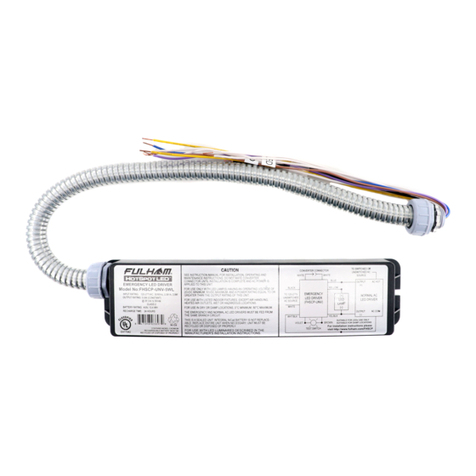
Fulham HotSpot LED FHSAC1-230-45CE User manual

FHSAC1-230-45CE
INSTALLATION INSTRUCTIONS
Fulham extends a limited warranty to the original purchaser or first user for a period of 5 years from the date of manufacture when properly installed
and operated under normal conditions of use. For complete terms and conditions, please refer to the Warranty Center at www.fulham.
Specifications subject to change without notice.
®
com.
Page 1 of 8
2017-718-1 Rev A
0-10VDC
Pulse DIM
02
EL-T
General Specifications
Input Voltage
Input Current
Input Power
Power Factor
THD
Output Current
Output Voltage Range
Output Power
Number of Output Channels
RFI/EMI
Ambient Operating Temperature Range
Sound Rating
Input Surge Protection
Protections
Service Life
20-240VAC, 50/60Hz 2
0.27. A Max.
58W
< % 20
SELV
11-50VDC
45W (1W to 6W @ Emergency)
1 Channel
A
Line-Neutral kV, Line & Neutral-Ground kV 2 2
Output Open Circuit Protection
Overload Protection
50,000 hours
2501400- mA
>0.9
Output Type
Over Temprature Protection
0°C To 40°C(32°F To 104F°)
EN55015
Standby Power <0.5W
Output runtime Minimum 90min at 6W, Minimum 180 Minutes at 3W (Factory set for 3W / 180min)
Dimming Type 0-10V or Pulse DIM
Dimming Percentage 0%, 1%-100%
Short-Circuit Protection
Battery Deep Discharge Protection
Safety Standards
Self-Diagnostic Factory Enabled
Mechanical Data Tolerance=±0.02"[ . ]
0 5mm
IEC/EN 61347-1,IEC/EN 61347-2-7,IEC/EN 61347-2-13,IEC/EN 60598-1
EN 61547,EN 55015 , EN 61000-3-2 , EN 61000-3-3
IEC/EN 60598-2-22,IEC 62384,EN 62493,IEC / EN 62034

FHSAC1-230-45CE
INSTALLATION INSTRUCTIONS
®
Page 2 of 8
Fulham extends a limited warranty to the original purchaser or first user for a period of 5 years from the date of manufacture when properly installed
and operated under normal conditions of use. For complete terms and conditions, please refer to the Warranty Center at www.fulham.
Specifications subject to change without notice.
com.
Manufacturer:
North China
Fulham Electronic Co. Ltd.
No. 9 Xingchang Road, Nanshao Zhen Changping Science Park, Beijing, P.R. China
Fulham Head Quarters:
Fulham Co., Inc
12705 South Van Ness Ave.
Hawthorne, CA 90250
Local: (323) 779-2980, Fax: (323) 754-9060
2017-718-2 Rev A
0-10VDC
Pulse DIM
02
EL-T
Important Safety Instructions
Caution: Do not let power supply cords touch hot surfaces.
Caution: Do not use outdoors.
Caution: Do not mount near gas or electric heaters.
Caution: Battery is rechargeable LiFePO4 type and must be recycled or disposed of properly.
Do not use this emergency driver with accessory equipment other than recommended by manufacturer;
failure to follow this may cause an unsafe condition. Servicing should only be performed by qualified service
personnel.
Important: An un-switched AC power source of 220VAC to 240VAC is required.
When using electrical equipment and this lighting device basic safety precaution should
be followed at all times including but not limited to the following:
PLEASE READ CAREFULLY AND FOLLOW ALL INSTRUCTIONS FOR YOUR OWN SAFETY
Do not use this emergency driver for other than intended use.
Equipment should be mounted in locations and at heights where it will not readily be subjected to
tampering by unauthorized personnel.
Important: Indicator (LED light) illuminated indicates battery in charge mode when AC power is applied.
It is recommended and required by applicable code to test emergency function to ensure proper operation of
the system; push the test switch for thirty (30) seconds every 30 days to ensure the emergency driver is
functioning as by illuminating the LED light source. Conduct a ninety minute (90) discharge test one time (1) per year;
LED light source should be illuminated for a minimum of ninety minutes (90).
ASSEMBLY and FIELD INSTALLATION WIRING: WARNING: AC power must be off before proceeding
with assembly or installation of emergency driver.
TESTING SYSTEM: The emergency battery requires a charge minimum of one (1) hour before testing the
circuit. A full charge requires twelve (12) hours.
Important: Double insulation used between the supply and battery circuit.
Important: Intermittent re-charging circuit.
Important: The recharging device remains safe after abnormal operating condition.

A Mounting the LED driver
Page 3 of 8
FHSAC1-230-45CE
INSTALLATION INSTRUCTIONS
®
STEP 1: Remove the Screw STEP 2: Remove the cover
STEP 3: Remove the Screws and strain covers
Lift
STEP 4: Mounting the LEDdriver
SCRE W: φ=4mm
B Making the wire connections 0.75-1mm² copper wire only and wire rated for 300V, 90°C minimum.
9-10mm
NOTE:1.Copper wire only
STEP 1:Wiring according to actual needs.
Press the cord wires into the strain relief slots.
Test switch
2 core wire
4 core wire
STEP 2: Put on the strain covers.
Fulham extends a limited warranty to the original purchaser or first user for a period of 5 years from the date of manufacture when properly installed
and operated under normal conditions of use. For complete terms and conditions, please refer to the Warranty Center at www.fulham.
Specifications subject to change without notice.
com.
2017-718-3 Rev A
0-10VDC
Pulse DIM
02
EL-T
SCRE W: φ=3mm

Page 4 of 8
FHSAC1-230-45CE
INSTALLATION INSTRUCTIONS
®
C Close the cover
STEP 1: Move battery switch to the "O FF" position.
STEP 2: Mounting the screw
Fulham extends a limited warranty to the original purchaser or first user for a period of 5 years from the date of manufacture when properly installed
and operated under normal conditions of use. For complete terms and conditions, please refer to the Warranty Center at www.fulham.
Specifications subject to change without notice.
com.
2017-718-4 Rev A
0-10VDC
Pulse DIM
02
EL-T
D Replace battery
Lift
STEP 1: Close the cover
STEP 2: Remove the screw
STEP 3: Remove the cover
SCRE W: φ=3mm

FHSAC1-230-45CE
INSTALLATION INSTRUCTIONS
®
D Replace battery
STEP 5: Install new battery
Fulham extends a limited warranty to the original purchaser or first user for a period of 5 years from the date of manufacture when properly installed
and operated under normal conditions of use. For complete terms and conditions, please refer to the Warranty Center at www.fulham.
Specifications subject to change without notice.
com.
0-10VDC
Pulse DIM
02
EL-T
STEP 6: Close the cover
Fulham extends a limited warranty to the original purchaser or first user for a period of 5 years from the date of manufacture when properly installed
and operated under normal conditions of use. For complete terms and conditions, please refer to the Warranty Center at www.fulham.
Specifications subject to change without notice.
com.
Close the cover Mounting the screw
Place the battery inside Re-connect battery connectors
Page 5 of 8
2017-718-5 Rev A
Make sure the wires are properly tucked inside compartment.
STEP 4: Remove the battery
Disconnect connector Take out the battery
Put a double adhesive tape on the bottom of the battery
(Recommended model 3M:DT542800081 )

Wall plate and screw color:
white with black lettering
Description: The Fulham FHSWLPWH Wall Plate can be used when remote mounting the Lighted Push Button Test Switch
Button Test Switch (LPBTS).
Page 6 of 8
Fulham extends a limited warranty to the original purchaser or first user for a period of 5 years from the date of manufacture when properly installed
and operated under normal conditions of use. For complete terms and conditions, please refer to the Warranty Center at www.fulham.
Specifications subject to change without notice.
com.
2017-718-6 Rev A
FHSAC1-230-45CE
LED+
LED-
LED ARRAY
TEST
SWITCH
0-10V/Pulse DIM
0-10V+/Pulse
0-10V -/Pulse
NTC/TPSB-100E
NTC / PRG+
NTC / PRG-
L2
N
L1
E
L
N
GND
WALL SWITCH
E
L1
N
L2
Loop Out
FHSAC1-230-45CE
0-10V+/Pulse
0-10V -/Pulse
FHSAC1-230-45CE
INSTALLATION INSTRUCTIONS
®
0-10VDC
Pulse DIM
02
EL-T
(
LPBTS) next to the fixture, on the wall or in any location within the maximum remote mounting distance (15 meters) of the Lighted Push
(The test switch can be used together with
Fulham FHSWLPWH Wall Plate.)
Pulse Dimming switch

FHSAC1-230-45CE
INSTALLATION INSTRUCTIONS
®
Page 7 of 8
Fulham extends a limited warranty to the original purchaser or first user for a period of 5 years from the date of manufacture when properly installed
and operated under normal conditions of use. For complete terms and conditions, please refer to the Warranty Center at www.fulham.
Specifications subject to change without notice.
com.
2017-718-7 Rev A
0-10VDC
Pulse DIM
02
EL-T
Self-Diagnostic tests to insure the unit is properly functional . It will test the following parameters:
*Battery-Checks to insure battery is properly connected and has sufficient capacity for 180
minutes when set to 1-3W or 90 minutes when set to 4W-6W
*LED load-Insures LED load is connected properly and functional.
*Charging circuit-Insures unit charging circuit is functioning properly.
Any errors will be shown via the indicator light as per the table below:
LED indicators on TEST SW System Status
Permanent green System OK
Slow flashing green
(1 sec on – 1 sec off) Self-Diagnostic process underway
Flashing Red
(4 sec on – 1 sec off) Battery not connected, check BAT pack
Solid Red Load failure, check EM LED load.
Slow flashing red
(1 sec on – 1 sec off) Battery failure, replace BAT pack.
Fast flashing red
(0,5 sec on – 0,5 sec off) Charge circuit error, replace EM Driver.
Both Green & Red off EM Mode
TEST SWITCH OPERATIONS:
Emergency Test Mode
1. Press and Hold Test Button to test Emergency Mode.
This can be done in all normal AC powered situations including dimmed to off and switched off.
Manual Self-Diagnostic
1. Quickly Press Test Button 3 times within 3 seconds to manually activate Self-Diagnostic cycle.
This will test the unit for 180 minutes when EM power set for 1W to 3W or for 90 minutes when
EM power is set for 4W or 6W.
2. To Exit the Self-Diagnostic cycle, Press and Hold Test Button for 5 seconds
Enable / Disable Auto Self-Diagnostic
1. Press and Hold Test Button for 3 seconds
2. Release and Quickly Press Test Button 2 times
3. Press and Hold Test Button again for 3 seconds
4. Green Indicator on Test Button will flash for 5 seconds indicating the Enabled or Disabled
Status :
Short off / Long on = Enabled
Long off / short on = Disabled

The Output Current, EM Power, Dimming Profile and Auto Self-Diagnostic Status can also be configured by using
the Fulham SmartSet PC software.
PROGRAMMING:
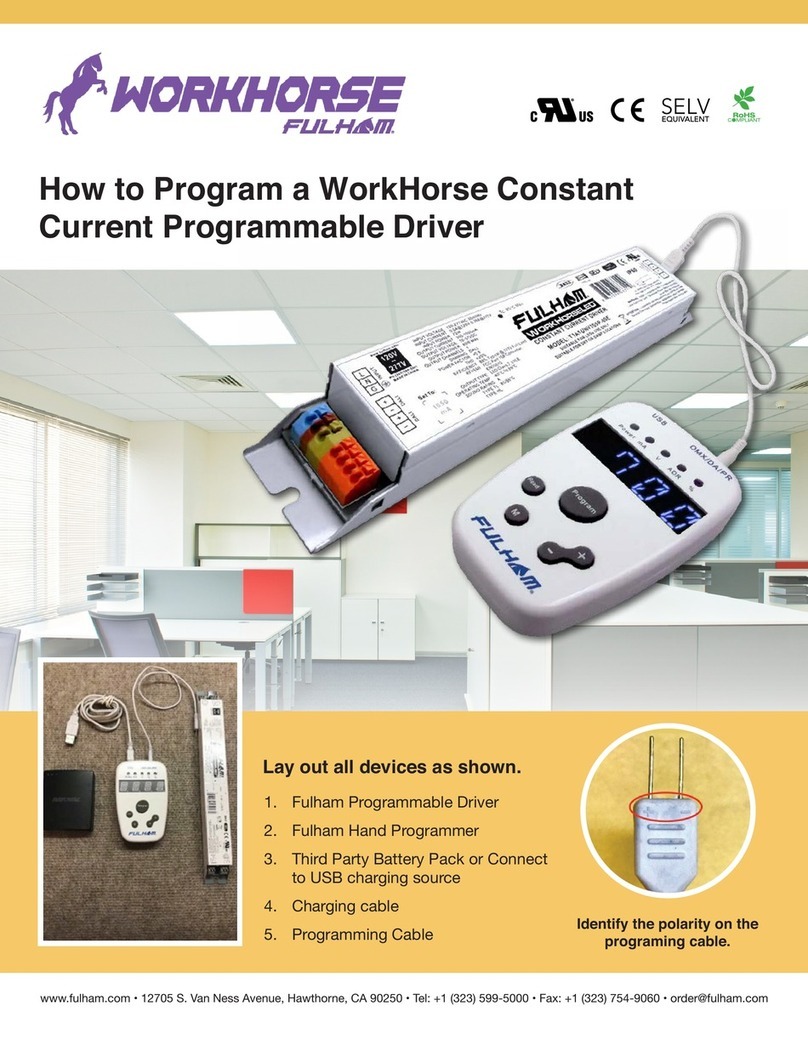
The following features can be programmed on this driver using the Fulham SmartSet TPSB-100E Handset:
* Output Current - 250mA to 1400mA
* Output EM power - 1W to 6W
* Enable / Disable Auto Self-Diagnostic Function
* Dimming :0-10V,0-10V Log,0-10V Custom or Pulse Dimming.
In order to configure the last 3 items, the TPSB-100E must be in FULL FEATURE mode.
Page 8 of 8
Fulham extends a limited warranty to the original purchaser or first user for a period of 5 years from the date of manufacture when properly installed
and operated under normal conditions of use. For complete terms and conditions, please refer to the Warranty Center at www.fulham.
Specifications subject to change without notice.
com.
2017-718-8 Rev A
FHSAC1-230-45CE
INSTALLATION INSTRUCTIONS
®
0-10VDC
Pulse DIM
02
EL-T
*For more detailed programming instructions please see our Programming Instructions and Design
Guide found on our website.
Table of contents
Other Fulham Controllers manuals
Popular Controllers manuals by other brands

Sauter Components
Sauter Components flexotron 300 manual

Infineon
Infineon ICE2HS01G Application note

Mitsubishi
Mitsubishi FX3U-20SSC-H user manual

Gopel Electronic
Gopel Electronic G CAR 6282 manual

elero
elero InDrive M30/1.6 RH Operating and assembly instructions

FMC Technologies
FMC Technologies Sening EPE2 installation manual