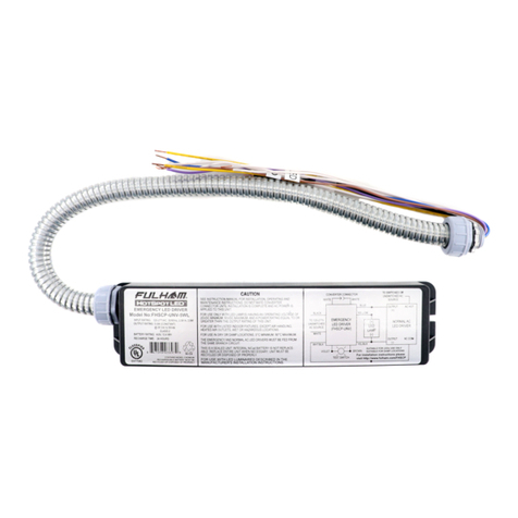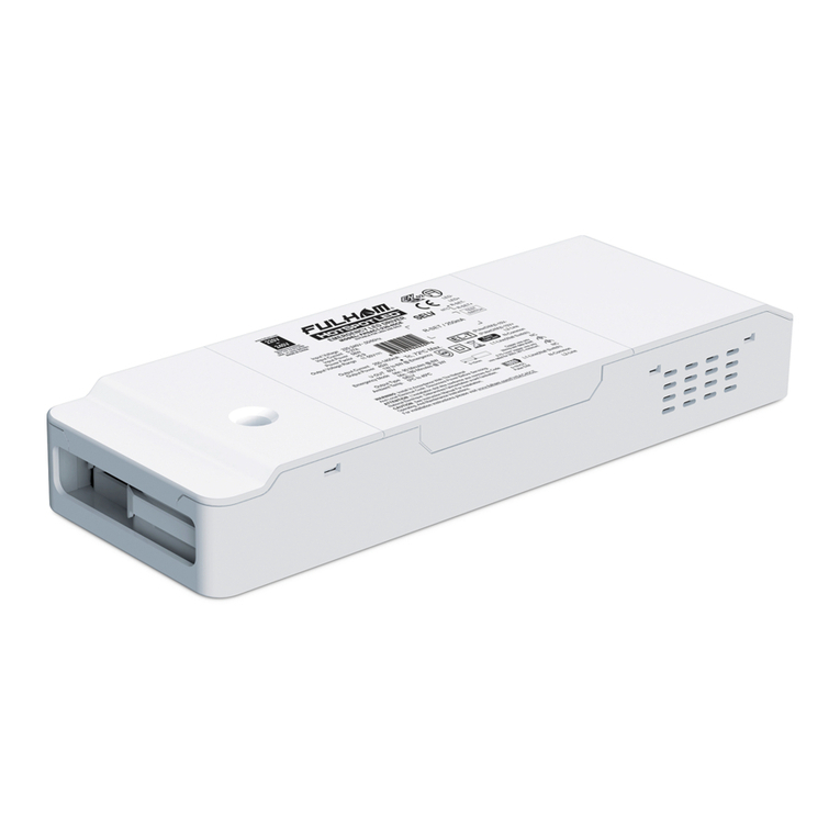
Drivers with Programming
Push-In Connectors:
Programmable drivers with push in connectors can be programmed
using either the larger or smaller pitch fork cables. Simply insert the
forks directly into the connectors labeled R-SET/PRG/NTC, ensure
that proper polarity is established otherwise an error code will be
displayed.
*RefertotheTPSB-100/EUserManualforfurtherdetailsonerrorcodes.
Plug the programming cable into the R-Set Port, making sure to
match the polarity as shown. The polarity indications on the cable
should be facing up towards you as shown.
Note: A mismatch in polarity will cause the programmer to read E-3 (
Error )
Note: Some Fulham Drivers have the polarity indicated with the
positive appearing to the left and the negative appearing to the right.
In that case, the indicators on the programing cable would be facing
down.
Programmable drivers with leads are programmed using the wire
block adapter.
Insert the prgramming cable into the back of the adapter, taking care
to matchy polarity.
For drivers with orange and yellow leads, connect the orange wire to
the red/positive connector and the yellow wire to the black/negative
connector.
For drivers without orange and yellow leads, the 0-10V leads are
used for programming. Connect the purple wire to the red/ positive
connector and the gray wire to the black/negative connector. If
programming while the driver is powered, a power cycle is required
for the new programmed current to take effect.
Programmable drivers with wires can be programmed using the
wire block adapter. Insert either the larger or smaller pitched fork
cable into the back of the adapter. Ensure that proper polarity is
established. Next insert the wires labeled R-SET/PRG/NTC into the
Red (+) and Black (-) quick release connectors located on the top of
the adapter. The polarity of the programming wires are as follows;
Orange Wire (+), Yellow wire (-), Purple Wire (+), Grey Wire (-), Red
Wire (+), Black Wire (-).
*Applicable drivers will use the 0-10V dimming wires as the programming wires. If
programmedwhilepowered,apowercycleisrequiredfortheprogrammedcurrentto
takeeffect.
Drivers with Programming Wires:
Programming setup for
drivers with leads
Programmable drivers with connectors on their output can be
programmed using the mating connector cable. If the drivers mating
output harness is plugged in, then they can be programed using the
wires labeled R-SET/PRG/NTC by plugging them into the Red (+)
and Black (-) quick release connectors located on the top of the wire
block adapter. The polarity of the program wires are as follows;
Orange Wire (+), Yellow wire (-), Purple Wire (+), Grey Wire (-), Red
Wire (+), Black Wire (-).
Drivers with Programming Connectors:
www
.fulham.com • 12705 S. V
an Ness Avenue, Hawthorne, CA 90250 • T
el: +1 (323) 599-5000 • Fax: +1 (323) 754-9060 •
[email protected]Identifying the correct connection method for programming
Step 1:


