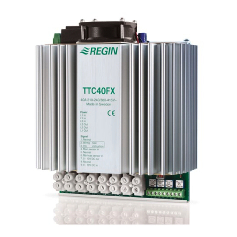
EN INSTRUCTION
PULSER...X010
IN20002 REV. A, 2018-05-14
CCaauuttiioonn!! Rea an un erstan the instruction before using the pro uct.
CCaauuttiioonn!! Ensure that the installation complies with local safety
regulations.
WWaarrnniinngg!! Before installation or maintenance, the power supply must first
be isconnecte in or er to prevent potentially lethal electric shocks!
Installation or maintenance of this unit shoul only be carrie out by
qualifie personnel. The manufacturer is not responsible for any eventual
amage or injury cause by ina equate skills uring installation, or through
removal of or eactivation of any security evices.
TECHNICAL DATA
Supply voltage ...230X...: 230 V ~ (207...253 V ~ 50/60 Hz 16 A)
...400X...: 400 V ~ (360...440 V ~ 50/60 Hz 16 A)
Ambient temperature 0…30 °C, non-condensing
Pulse period 6/60/120 s, adjustable
Mounting Wall
Protection class IP20
Dimensions, external
(WxHxD)
93 x 153 x 40
Output load Resistive load, max 16 A, min 1 A
Input signal 0...10 V DC
INSTALLATION
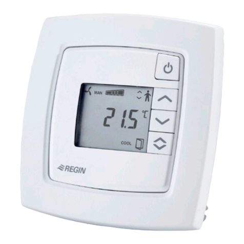
1. Remove the front. The locking screw is located behind the false set-
point knob.
2. Mount the unit vertically with the cooling flange at the top. Use
screws with a maximum head diameter of . mm. The mounting
holes have a centre distance of 60 mm in order for the product to fit
on a device box.
CCaauuttiioonn!! The electric heating controller emits approximately 20 W of
heat which must be issipate . Maximum ambient temperature at full
loa is 30 °C.
WIRING
– Terminal 1...2: Supply voltage (not polarity sensitive)
– Terminal 3...4: Output load (resistive heater)
– Terminal : Signal neutral
– Terminal 6: 0...10 V DC
– Terminal U: Outputs for wiring of PULSER-ADD
Figure 1 Terminals
The signal input terminals are galvanically separated from the supply
voltage. To minimize the influence from external disturbances, the signal
cable should be kept as short as possible (less than 2 m).
CCaauuttiioonn!! The supply voltage shoul be wire via an all-pole switch with a
minimum contact gap of 3 mm. The cooling flange is live.
SETTINGS
The electric heating controller pulses the full load On - Off. It adjusts
the mean power output to the prevailing power demand by
proportionally adjusting the ratio between On-time and Off-time. The
pulse period (=the sum of On-time and Off-time) is settable to three
different values using the jumper on the PC-board.
Figure 2 A = 6 seconds, B = 60 seconds (factory setting), C = 120 seconds
FUNCTION
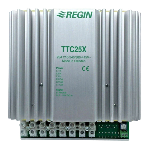
The electric heating controller is a complete proportional power unit for
electric heating. It is controlled by a 0...10 V DC signal from an external
controller. It pulses the whole load On - Off. The ratio between On-
time and Off-time is varied 0 - 100 % to suit the prevailing heat demand.
The current is switched at zero crossing to prevent RFI. The electric
heating controller is only intended for electric heating control. The
control principle makes it unsuitable for motor- or lighting control and it
cannot control 3-phase loads.
This product carries the CE-mark. More information is available at
www.regincontrols.com.
DOCUMENTATION
All documentation can be downloaded from www.regincontrols.com.
CONTACT
AB Regin, Box 116, 428 22 Kållered, Sweden
Tel: +46 31 720 02 00, Fax: +46 31 720 02 0
SE INSTRUKTION
PULSER...X010
OObbsseerrvveerraa!! Läs och förstå instruktionen innan u använ er pro ukten.
OObbsseerrvveerraa!! Se till att installationen uppfyller lokala
säkerhetsbestämmelser.
VVaarrnniinngg!! Innan installation eller un erhåll måste matningsspänningen först
kopplas från för att un vika potentiellt ö liga elstötar! Installation eller
un erhåll av enna enhet ska en ast utföras av kvalificera personal.
Tillverkaren är inte ansvarig för eventuella ska or som orsakas av felaktig
installation och/eller inaktivering eller borttagning av säkerhetsanor ningar.
12U34U 6 5
0...10 V DC
0
230/400 V AC
PULSER...X010
PULSER...X010 1
