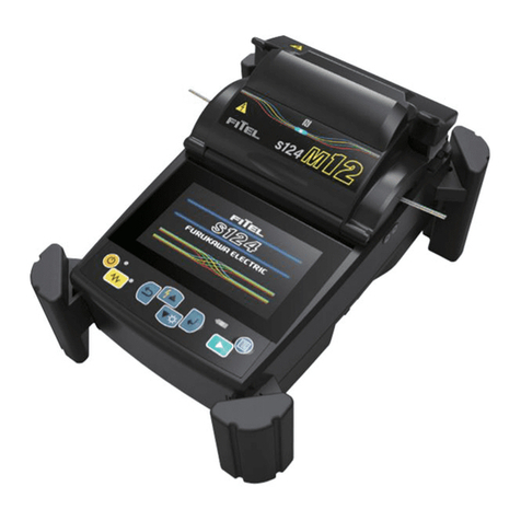
Furukawa electric Fitel S175 User manual

-~
ARTISAN
®
~I
TECHNOLOGY
GROUP
Your definitive source
for
quality
pre-owned
equipment.
Artisan Technology
Group
Full-service,
independent
repair
center
with
experienced
engineers
and
technicians
on staff.
We
buy
your
excess,
underutilized,
and
idle
equipment
along
with
credit
for
buybacks
and
trade-ins
.
Custom
engineering
so
your
equipment
works
exactly as
you
specify.
•
Critical
and
expedited
services
•
Leasing
/
Rentals/
Demos
• In
stock/
Ready-to-ship
•
!TAR-certified
secure
asset
solutions
Expert
team
ITrust
guarantee
I
100%
satisfaction
All
tr
ademarks,
br
a
nd
names, a
nd
br
a
nd
s a
pp
earing here
in
are
th
e property of
th
e
ir
r
es
pecti
ve
ow
ner
s.
Visit our website - Click HERE

FTS-8062-5
§I
75
version2000
SINGLE
-
FIBER FUSION SPLICER
User’s
Manual
Please read entire manual prior to usage.
This manual must be kept with the
S175
FusionSplicer.
Issue
5.
April
2000
4THE
FURUKRWA
€L€CTRIC
CO.,


Contents
1.
SafetyInformationand Instructions
1
.l.
Safety Information
1.2. Safety Messages
1.3. WARNINGS and CAUTIONS
1.4. Power Requirements
1.5. Fuses
1.6. LinePower Cord
1.7. Toxic Hazards
1.7.1.
Incineration
1.7.2.
Acidic or caustic compounds
1.7.3.
Physicaldamage
2.
GeneralInformation
3.
Operating Specificationsand Components
3.1. Specifications
3.2. Components
3.3. OptionalAccessories
3.4. RecommendedConsumable
4.1.
4.2. Side Panel
4.3. Main Body
5.
Getting Started
5.1. Unpackingand InitialInspection
5.2. Setup
5.3. Installingthe splice programs
5.4. Selecting the Operating Language
5.5. Arc check
6.1. Ready Screen
6.2.
FusionSplicing
4.
ExternalDescription
Operating Keysand Status
LEDs
4.2.1.
Rightside panel
4.2.2.
Left
side panel
6.
Operating Instructions
6.2.1.
Preparingthe Fiber
6.2.2.
Loadingthe Fiber
6.2.3.
FusionSplicing
6.2.4.
SplicingDefects
6.2.5.
Removingthe Spliced
6.2.6.
Reinforcingthe FusionSplice
6.2.7.
Changingthe FusionProgram
6.2.8.
Changingthe Heater Program
6.2.9.
Performingan Attenuation Splice (Optional)
7.
Maintenance and Handling Instructions
7.1. Error Messages
7.2. Maintenance
7.2.1.
Arc Check
7.2.2.
ElectrodeMaintenance
7.2.3.
Cleaningthe objectivelens
1
1
1
2
5
5
5
5
5
6
6
7
11
11
12
13
13
14
14
15
15
15
16
17
17
17
18
20
21
23
23
23
23
24
25
27
27
28
29
30
31
32
32
35
35
35
36

Contents
7.2.4. Cleaningthe Mirrors
7.2.5. Cleaningthe V
-
grooves
7.2.6. Cleaningthe V
-
groove FiberClamps
7.3. Storingand Shipping
7.4. Claims and Repackaging
7.5.
8.1. ProgrammingFunctionsand Menu
8.2. Modifyinga Fiber Program
8.3. Modifying
a
Heater Program
8.4. Splice Data
ReturnShipmentsto The FurukawaElectric
Co.
8.
Programming
Guide
8.4.1. Viewingthe data
8.4.2. Adding a Comment
8.4.3. Printingthe Data
8.4.4. Clearingthe data
8.5. Arc Check History
8.6. Configuration
8.6.1. Language
8.6.2. Arc Counter
8.6.3. TotalArc Counter
8.6.4. SleepTime LCD
8.6.5. DataOutput
8.6.6. LowTemp. Motor Rate
8.6.7. LowTemperature
8.6.8. TENSIONTEST
8.6.9. EstimationLoss
8.6.10. Arc Count Reset
8.7. EnvironmentMonitor
8.8. ManualOperation
8.9. RustCheck
8.1
0.
Motor LimitTest
8.11. Fiber Dimension
8.12. Program Management
8.12.1,
ProgramStore/ Default
8.12.2. PROGRAM
COPY
8.12.3. PROGRAM DELETE
8.13. Adjust Raterime
37
37
37
38
38
38
39
39
41
45
48
48
49
49
51
52
52
52
52
53
53
53
53
54
54
54
54
56
56
57
57
58
61
61
63
64
64

Safety Informationand Instructions
A
WARNING
CAUTION
This manual contains complete operating and maintenance instructionsfor
THE
S175
FUSIONSPLICER. Pleasereview this manualcarefully before operating.
Referto the User’sManualfor instructionson handlingandoperating
The procedurecan result inserious injury or
loss
of lifeif not
carried out in proper compliancewith all safety instructions.
Ensurethat all conditions necessaryfor safe handlingand
operationare met before proceeding.
The procedurecan result inserious damageto or destructionof the
instrument
if
not carriedout incompliance with
all
instructionsfor
proper use. Ensure that
all
conditionsnecessaryfor safe handling
and operation are met before proceeding.
1
the instrumentsafely.
1
.l.
Safetv Information
The followingsafety instructions must beobservedwhenever the
S175
fusionsplicer is
operated, serviced or repaired. Failureto comply with any of these instructionsor with
any precaution or warning contained
in
the User’s Manual is
in
direct violation of the
standards of design, manufacture and intended use of the instrument. The Furukawa
Electric Co., Ltd. assumes no liability for the customer’s failure to comply with these
safety requirements.
1.2.
Safety Messages
0
Pleasecontact The FurukawaElectricCo., Ltd. or your localrepresentativewith any
questions relatingto any subjects describedwithin this manual.
0
Inno case will The FurukawaElectricCo., Ltd. be liableto the buyer, or to any third
parties,for any consequentialor indirectdamagewhich iscausedby productfailure,
malfunction, or any other problem.
1

Safety Informationand Instructions
1.3.
WARNINGS
and
CAUTIONS
WARNI
0
This is a Class A product of EN 55022(1994). In a domestic environment this
product may cause radio interferenceinwhich case the user may be requiredto
take adequate measures.
0
The power cord supplied with this equipment must be connected to a power
socket, which provides
a
reliable protective earth. Or, ground it with the Ground
terminal on the fusion splicer.
0
Useonly the cords attachedto the fusion splicer. Connectinginappropriatecords
or extendingthecords may causethem to heatupabnormally and may causefire.
0
This product contains
a
Lithium Cell. The device is identified by
a
warning label.
Do not dispose of infire. Disposalof this device must be carried out by qualified
personnel.
0
Never touch the electrodeswhen the fusion splicer is poweredon. Doing
so
may
cause electrical shock.
~~ ~
Do
not operatethe fusion splicer without electrodes.
0
Do not disassemble the instrument except
as
described in the maintenance
section of this manual. The fusion splicer contains no user serviceable parts.
Warranty on this productwill beinvalidatedif any of the pottednuts are disturbed.
~~
0
Avoid soaking the fusion splicer with water. Doing
so
may cause fire, electrical
shock or malfunction.
0
Do not use inappropriateinputvoltage. Doing
so
may causefire, electrical shock
or malfunction.
0
Do not insert or drop any metal or any flammable material into the main body
through any aperture. Doing
so
may causefire, electricalshock or malfunction.
0
Avoid direct skin contactwith the heatingportion. This may cause burnor injury.
0
Do not removethe panelsof thefusionsplicer. Some partsgeneratehighvoltage.
Removingthe panels may cause electricalshock.
~~ ~
0
If abnormal sounds or extra high temperatures are observed, turn
off
the power,
disconnect the power cord and contact The Furukawa Electric Co., Ltd. or your
localrepresentative. Continuingto operate undertheseconditionsmay causefire
or electrical shock.
0
Do not use a damaged power cordwhere the inner cable is exposed or severed.
Doing
so
may causefire or electricalshock.
2

Safety Informationand Instructions
0
If water is spilled intothe fusion splicer, turn
off
the power switch, disconnect the
power cord and contact The Furukawa Electric Co., Ltd. or your local
representative. Continuingto operate under these conditions may cause fire or
electricalshock.
0
If smokeor strangesmells areobserved, turn
off
the powerswitch, disconnectthe
power cord and contact The Furukawa Electric Co., Ltd. or your local
representative. Continuing to operate under these conditions may cause fire,
electricalshock or malfunction.
0
Ifthefusionsplicerisdroppedanddamaged,turn
off
thepowerswitch,disconnect
the power cable and contact The Furukawa Electric
Co.,
Ltd. or your local
representative.Continuingto operate may causefire or electricalshock.
3

Safety Informationand Instructions
0
Do not place the fusion splicer on an unstable or inclined surface. There is a
0
Disconnect
all
cordswhen movingthefusionsplicer.Failuretodo
so
maydamage
0
Do
notplacethe cords aroundany heatinginstrument. Doingso may damagethe
0
Do
not connect
or
disconnect cords with wet hands. Doingso may cause fire or
possibilitythat thefusion splicer will fall and cause injury.
the cords which may causefire or electricalshock.
cordswhich cause fire or electricalshock.
electricalshock.
0
Do
not pull the cord to disconnect. Doing so may damage the cords which may
causefire or electricalshock. Holdthe plugportion and disconnect the cord.
0
Do not putheavy items on the cords. Doingso maydamagethe cordswhich may
causefire or electricalshock.
0
Do
not modify the cords and do not over
-
bend, over
-
twist, or over
-
stretch the
I
cords. Doing
so
may causefire or electricalshock.
__~
~
0
Ensurethat the cords are disconnectedwhenstoringthe fusionsplicer.
0
Never use aerosol dust cleaners or alcohol
-
based solvents to clean the
0
Nonoil
-
basedsolventsshould be usedto cleanthe optical lenses.
electrodes.
0
Storethefusionsplicer
in
a cool dry place.
4

Safety Informationand Instructions
1.4.
Power Requirements
The
S175
fusion splicer can operate from any single
-
phase
AC
power source that
supplies between
100
-
120
V
and
200
-
240
V
at
a
frequency of
50
Hz to
60
Hz
,
or from
DC
10
-
16
V.
1.5.
Fuses
Useonly the correctsizeof
250
VAC
fuse as specifiedinthis manual.
1.6.
Line Power Cord
The
S175
uses
a
three
-
wirepowercordequippedwith
a
protectiveearthcontact.
Do
not
connect
an
extensioncordthat does not have this feature.
When connected to
an
appropriate
AC
power source, the power cord grounds
the
instrument chassis.
A
WARNING
To
avoidthe riskof injuryor death, ALWAYS observethe
followingprecautions beforeinitializingthe
S175
fusionsplicer.
Do
not connect both
AC
and
DC
power sources
at
thesame
time. Connect onesourceor theother.
If
using
a
voltage
-
reducingautetransformerto power the
S175
fusionsplicer, ensurethat the commonterminal
connectstotheearthedpoleof the power source.
Use onlythetypeof powercordsuppliedwiththe
S175
fusion
splicer.
Connectthepower cordonly to
a
power outlet equippedwith
a
protectiveearth contact. Never connectto an extension
cordthat isnotequipped
with
thisfeature.
Willfully interruptingthe protectiveearth connectionis
prohibited.
1.7.
Toxic Hazards
Undernormalconditions of use, storage, andhandlingthe
S175
fusionsplicerpresents
no toxic hazards. However, under the following conditions, certain precautions are
necessary.
1.7.1.
Incineration
Some of the electronic components included in the assembly are constructed with
resins and other chemicals that producetoxicfumes during incineration.
5

Safetv Information and Instructions
1.7.2. Acidic
or
caustic compounds
Some of the electronic components included in the assembly, particularly electrolytic
capacitors, contain acidic or caustic compounds. In the event that
a
damaged
componentcomesincontactwiththeskin,washthe affectedareaimmediatelywithcold
water. Intheevent
of
eye contamination,irrigatethoroughlywith
a
recognizedeye
-
wash
andseek medical assistance.
1
J.3.
Physicaldamage
Some
of
the components used in the assembly may contain very small quantities
of
toxic materials. There is
a
remote possibility that physically damaged electronic
components may present a toxic hazard.
As
a general precaution, avoid unnecessary
contact with damaged electronic components, and arrange
for
disposal
in
accordance
with localregulations.
6

General Information
Fusion splicing is used to physicallyjoin together
two
optical fiber ends; the process
may vary, depending on the type of fusionsplicer used. The
S175
Single
-
Fiber Fusion
Splicer has
an
active corealigning mechanismto alignthefiber ends and acontrollable
electric arc to melt the glass and butt the ends together. This results in
a
strong joint,
withvery low
loss
andvery low back
-
reflection.
To
achievegood splicing results, it isessentialto know boththe proper use of
a
fusion
splicer and the characteristicsof opticalfiber. Because not all fibers are identical,they
can melt or fuse at different temperatures. Therefore, to minimize splice
loss,
it is
importantthatthearc powerandthe durationof thefusionarc beproperlyadjusted.The
S175
fusion splicer features an inspectionof arc function to help the user adjust these
parameters.
Other intrinsic factors that contribute to the increase in splice
loss
are core diameter
mismatch, cladding diameter mismatch, numerical aperture mismatch, core
concentricity and noncircularity.
Core Diameter Mismatch
Cladding Diameter Mismatch
NumericalAperture Mismatch
Different fibers have different numerical apertures. The aperture dictates the
acceptance angle of light.
7

General Information
Coating
standarddiameter
material
standarddiameter
material
Cladding
Core
standard diameter
CoreConcentricity
250
pm,
900
pm
acrylic resin, nylon
125
pm
silica, Fluoro doped silica,
Titan
-
coatedsilica
8
pm
-
10
pm
(SM)
50
pm
-
62.5 pm
(MM)
Core Noncircularity
core2
-
core1
Optical fiber is basically classified
as
either single
-
mode
(SM)
or multi
-
mode
(MM).
Single
-
modefiber, which includes dispersion
-
shiftedfiber types, will transmit a single-
mode (path) of data at wavelengths greater than the cut
-
off wavelength
(1
170
nm).
Approximately
80%
of the light
is
transmittedwithin the core, and
20%
istransmittedin
the surrounding cladding. Therefore, the transmissionpath is more accurately referred
to
as
the mode field and not as the core. With a core diameter of typically
8
pm and
a
modefield diameter
of
approximately
10
pm, single
-
modefiber cantransmit moredata
than multi
-
modefiber and with less attenuation.
In
multi
-
modefiber, the opticalsignalis transmittedentirelywithin the core. Thesefibers
have
a
core size of
50
pm to
100
pm
(50
pm
or
62.5
pm, typically) and are commonly
used in local area networks
(LANs),
short distance links and closed circuit television
PhysicalCharacteristicsof Optical Fiber for Fusion Splicing
(CCn/)-
material
I
Germaniumdopedsilica, silica
I
a

Transmittingcapacity
Splice
loss
Splicing ease
Physical Characteristics
of
Single
-
modeand Multimode Fiber
50/125
Multimode
62.51125
Multimode
Dispersion- Single
-
mode Multimode
shifted
superior high
low
difficult middle easy
high middle very
low
125
pm
corm
tran;mits light dadding
keeps
opbcal
signal
within
core
Singlemode
125
pm
100/140
Multirnode
140
pm
1
coating
protects
glass
from
abrasion
and ensures high strength
r-T>
typical
diameter
of
human
hair
9

General Information
~~~~~~ ~~ ~
Core Diameter/Axisoffset
Becausethe optical signal is transmittedthrough the core of the fiber, it is important to
understand how the cores of the
two
fibers being spliced together compare. The
following general formula can be used to show the effects of core offset on the splice
loss.
The formula is only theoretical and does not take into account other extrinsic
factors such as cleavequalityanddust contamination,andintrinsicfactorssuch as core
noncircularity and numericalaperture.
mode field diameter
Npm]
mode field diameter B[vm]
optical
power
INPUT
____,
core
axis
offset d[pm]
I
optical power
OUTPUT
right
fiber
\
leftfiber
L
splice
loss
splice
loss
=
I
o
x
log,,
OUTPUT
=
I
o
x
[(
2AB
EXP(-
2d’
)]
INPUT
A’
+
B‘
A‘
+
B’
A
difference between
A
and
B
will cause a splice
loss,
even
if
d is zero.
If
using
single-mode fiber, the manufacturer
of
the fiber may be able to provide mode field
diameter specifications.
is
impossible to have perfectly centered cores, because fiber manufacturing
limitations often resultinsmall offsets. Today’s opticalfibers arewell manufacturedand
havecoreeccentricityof lessthan0.5pm. However, olderfiber exhibits coreeccentricity
near
1
.Opm.
The
S175
fusionsplicer, which has an active core alignmentfunction by observing the
core positionwith microscopeand image processor, aligns the cores of both fibers to
minimizethe axis offsetdescribedabove.

OperatingSpecificationsand Components
3.1.
Specifications
Fiber cladding diameter
I
Coatedfiber range
Fiber strip length
(1Omm is optional
for
900 pmcoating)
Average splice
loss
(Identical fibers)
Single
-
mode
Multi
-
mode
Dispersionshifted
Operatingtemperature
Storagetemperature
Humidity (Non condensing)
Environmental
Electrical
Inputterminalsfrom AC supply
Dimensions
Splicer
Carrying case
Splicer
Carrying case
Splice Data
Arc Check History
Programstorage
FusionProgram
Heater Program
Weight
Data storage
Typical Splice time
Typical Reinforcingtime
~
Minimum
100
10
-
1
0
-
40
10
Typical
-
250,900
16
0.02
0.01
0.04
100
-
120
200
-
240
12
27
~~ ~
Maximum
150
50
60
95
16
70
181Wx 285D x 181H
470W x 291Dx 420H
6.3
4.8
400
100
32
Q
U
19 (AccurateEstimationMode)
17(High Speed Mode)
75
(withS922)
/
90 (withS921)
~____
~
Units
mm
dB
dB
dB
"C
"C
%R.H.
VAC
VDC
Watt
mm
mm
splices
checks
see
sec
11

OperatingSpecificationsand Components
3.2.
ComDonents
Sparefuse
Carryingcase
DC Connector
Part Part Number Quantity
S175X-06 1
pair
S175X-07
1
S175X-08 1
Main body
DC power cord
RS
-
232Ccord
Battery
S175X-01
I
1
S
175X
-
A01 1
S
175X
-
A02 1
S
1
75X
-
A04 1
Top
cover
~
S1
75X
-
02
I
1
Work table S175X-03
I
1
AC Power cord S175X-04
1
Spare electrode S175X-05 1pair
User's manual
I I
1
b

Operating Specificationsand Components
3.3.
OptionalAccessories
ContactThe FurukawaElectric
Co.,
Ltd. or your local representativefor
a
moredetailed
specification.
S210
stripper
S321
precisioncleaver
S323
precisioncleaver
S901
high
-
capacitybattery
S902
printer
S322TR
precisioncleaver for Titanfiber
S423
Tool kit (including
S210
and
S321)
S921
60mm lengthsplice protectionsleeves
S922
40mm lengthsplice protectionsleeves
3.4.
RecommendedConsumable
Keep a supply of the following itemswith the
S175
fusion splicer at all times.
Spare electrodes (Part No.
S175X-05)
Fuse
(Part
No.
S
175X-06)
Tweezers
Protectiveeye glasses
Electrodecleaningblock
Denaturedalcohol
Lint
-
freetissues or swabs
Containerfor disposal of scrap fiber
13

External Description
4.1.
Operating Keys and Status
LEDs
Kevs
I
Function
Initiates, pauses and resumes the fusion
splicing cycle.
Escapes an operation, and returns to the
orevious menu.
Changesthe parameter value.
Initiates an arc
for
fusion splicing and an
additional arc.
I
Changesthe parameter value.
'OWE'
(LED)
I
Indicatespower condition. (Seebelow)
1
Brightness control for LCD Monitor.
(Volume)
I
-
POWER
LED
indicates thepower conditions as below.
~~~ ~
LED
color Power conditionwith Power conditionwith
AC
input
(c85Vor 265k)
Inappropriatevoltage Inappropriatevoltage
(4
OV
or
17.5Vc)
Red
Lower voltage
(10-1
1\A
1
Orange
I
I
Green Appropriate voltage Appropriate voltage
14

ExternalDescription
4.2.
Side Panel
4.2.1.
Right
side panel
Label
SERIAL
PORT
VIDEO
.2.
Left side panel
Description
RS-232C
interfacefor data communication
PIN connectorfor video output
15
Table of contents
Other Furukawa electric Welding System manuals