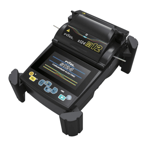
Furukawa electric FITEL S122 User manual

DESCRIPTION
FEATURES & APPLICATIONS
TECHNICAL INFORMATION - CONNECTOR
FITEL’s new connector termination system allows for unsurpassed
performance and flexibility in the field.
This new “splice-on” connector eliminates the need for field polishing
and significantly improves the quality of the termination and installa-
tion time required.
FITEL’s factory polished ferrules with pre-cleaved fiber stubs are spliced
onto the field fiber utilizing FITEL’s proprietary ferrule holder and
fusion splicer. Once spliced, the SC/APC or SC/UPC connector is easily
assembled by using a process that requires minimal skill or training.
TYPE
SC/Ultra PC; FC/Ultra PC SC/Angled PC; FC/Angled PC
Insertion Loss Typical 0.30dB
Reflectance < - 55dbB < -65dB
Fiber Type SMF
Jacket Type 900µm, 2mm, 3mm
Ferrule Type Zirconia ceramic ferrule with pre-polished fiber stub
• Simple, Fast, & Consistent Field Termination
Allows for easy field repair of pre-terminated splitters, fan outs, and drop terminals.
• No Polishing or Epoxy
FITEL’s connector termination process requires no polishing or epoxy increasing the quality and consis-
tency of field connector termination. Total installation time is greatly reduced compared to traditional
methods.
• Fiber Management
The most difficult task for splicer operators has always been managing the fiber upon completion of
splicing. The connector termination feature on the S122A and S177A eliminates the need for splice trays
resulting in easier fiber management, reduced storage requirements, and faster installation times.
TECHNICAL INFORMATION - SPLICER
TYPE
S122C S177AX-02
Splicing Method Clad-Alignment Core-Alignment
Fiber Type SMF, MMF, DSF, NZDSF SMF, MMF, DSF, NZDSF, EDF, etc.
Insertion Loss Typical 0.05dB (SMF) Typical 0.02dB (SMF)
Battery Capacity 50 splice cycles 70 splice cycles
Applicable Sleeves 20 - 60mm 20 - 60mm
CONNECTOR TERMINATION SYSTEM

900µmCONSTRUCTION
2 & 3mm CONSTRUCTION
ORDERING INFORMATION
S122 S177 SOC CONNECTORS
Furukawa reserves the right to improve, enhance, and modify the features and specifications of FITEL products without prior notification
For Ordering Information Please Contact:
Furukawa Electric Europe Ltd.
3rd Floor Newcombe House
43-45 Notting Hill Gate
London W11 3FE
Phone: +44 20 7221 6000
Fax: +44 20 7313 5310
Web: http://www.furukawa.co.uk
CONNECTORS
CONNECTOR TERMINATION SYSTEM
PART NUMBER DESCRIPTION
S122C S122C Clad Alignment Fusion Splicer
S177AX-02 S177AX-02 Core-Alignment Fusion Splicer
S122C-SOC Kit S122 Connector Termination Add-on Kit
S177A-SOC Kit S177 Connector Termination Add-on Kit
SSCS-PN1 SC/APC Splice-On-Connector, 900um
SSCS-PN2 SC/APC Splice-On-Connector, 2mm
SSCS-PN3 SC/APC Splice-On-Connector, 3mm
SSCS-P1 SC/UPC Splice-On-Connector, 900um
SSCS-P2 SC/UPC Splice-On-Connector, 2mm
SSCS-P3 SC/UPC Splice-On-Connector, 3mm
SAPS-388 FC/APC Splice-On-Connector, 900um
SAPS-386 FC/APC Splice-On-Connector, 2mm
SAPS-387 FC/APC Splice-On-Connector, 3mm
SAPS-358 FC/UPC Splice-On-Connector, 900um
SAPS-356 FC/UPC Splice-On-Connector, 2mm
SAPS-357 FC/UPC Splice-On-Connector, 3mm
Europe Ltd.

Splice-On-Connector Quick Reference Guide - 250 & 900µm
1234 5
67 89
Remove ferrule from
packaging using ferrule
transportation tool.
Place ferrule in ferrule
holder using ferrule
transportation tool.
Place ferrule holder
directly into fusion splicer
Slide field fiber through
main body connector parts
inside packaging. Then
remove.
Slide included 20mm
protection sleeve onto field
fiber.
Load fiber into fiber holder
leaving approximately 1.25
inches protruding from holder.
Prepare field fiber for
fusion splicing using
standard procedure.
Slide splice sleeve over
spliced fiber
Protect splice with heat
shrink oven
Remove Transportation Tool
Slide outer housing over
inner housing. Inner housing
is keyed to outer housing.
COMPLETE!
10
11 12 14 15
Slide up main body and spring.
Place inner housing over main
body and ferrule (for APC align
dot with round side of inner
housing). Main body is keyed to
inner housing.
Use Connector Assem-
bling Tool to snap on
inner housing to main
body.
13

Splice-On-Connector Quick Reference Guide - 2 & 3mm
Remove ferrule from
packaging using ferrule
transportation tool.
Cut kevlar leaving approxi-
mately 1/4 inch protruding
from cordage.
Slide 20mm protection sleeve
over splice point, shrink in
heat shrink oven.
Crimp “crimp ring” onto main
body using 0.190 round.
Use Connector Assembling
Tool to put approximately 3/4
inch slit into cordage (Guide
on side of tool).
Place ferrule in ferrule holder
using ferrule transportation
tool.
Place ferrule holder directly
into fusion splicer.
Remove protection sleeve
from packaging and slide
onto 900µm fiber.
Remove protected fusion
splice from fusion splicer.
Remove split cordage from
underneath “crimp ring.”
Slide up main body and
spring. Remove ferrule trans-
portation tool.
Crimp “sleeve” onto “crimp
ring” using 0.178 hex slot.
Slide cordage fiber through
connector parts inside of
packaging.
Place fiber into cordage holder
with slit facing up as shown.
Sleeve protrudes slightly from
fiber holder with metal rein-
forcement facing down.
Place inner housing over main
body and ferrule (for APC align
dot with round side of inner
housing). Stop ring is keyed to
inner housing.
Slide boot over components.
Main body is keyed allow-
ing for boot to rest in proper
position.
Use Connector Assem-
bling Tool to snap on inner
housing to main body.
Place thumb firmly on rear
of fiber holder and strip
fiber from fiber holder edge
(leaving approximately
4mm of coating protruding
from holder).
Clean fiber, cleave fiber, load
into splicer, and splice.
** Tension test is not applicable and
should be in OFF position before
splicing.
Slide outer housing over in-
ner housing. Inner housing
is keyed to outer housing.
Slide up “crimp sleeve” so
that the kevlar is pinched
between crimp sleeve and
main body.
Remove cordage with
connector parts attached.
Remove approximately 2
inches of cordage.
1 2 3 4 5 6
7 8 9 10 11 12
13 14 15 16 17 18
19 20 21 22 23
COMPLETE!
24

FTS-B310-1
May 2007
S240A Slitter Snapper Operating Instructions
・ Please read entire manual prior to usage.
・ This manual must be kept with the S240A Slitter Snapper.
Safety Instructions
This manual contains the complete operating and maintenance instructions for S240A
Slitter Snapper. Please review this manual carefully before operating the S240A Slitter
Snapper.
The following safety instructions must be observed whenever this product is operated,
serviced or repaired. Failure to comply with any of these instructions or with any
precaution or warning contained in this manual is in direct violation of the standards of
the design, the manufacture and the intended use of the instrument. THE FURUKAWA
ELECTRIC CO., LTD. assumes no liability for the customer’s failure to comply with
these requirements.
Safety Instructions
!
CAUTION Failure to comply with any of the instructions, which are indicated by
this symbol, may cause serious injury or damage to the machine.
Please contact THE FURUKAWA ELECTRIC CO., LTD. with any questions relating to
the description of this manual.
In no case will THE FURUKAWA ELECTRIC CO., LTD. be liable to the buyer, for any
consequential or indirect damage which is caused by product failure, malfunction, or
any other problem.
!CAUTION
•
•
•
•
•
•
•
Avoid soaking the S240A Slitter Snapper with water. Doing so may cause malfunction.
Do not drop, throw, and disassemble. Doing so may cause malfunction.
Ensure that cleaning the S240A Slitter Snapper and slit fiber cordage, before slitting. If not
doing so, it may occur that fiber breaking or irreguler slit, because of dust.
Do slit slowly. If ribbon fiber cannot be slit smoothly, interrupt slit and cleaning. If
smoothness is not recovered, it is possible that the S240A Slitter Snapper has
malfunctioned or fiber has deformed. Stop slitting till the cause is cleared. If slit is done with
continue, it may occur fiber breaking or add the damage to fiber.
The S240A Slitter Snapper is designed with special attention to prevent damage to the fiber.
But there are possibilities of damaging fiber, in condition of fiber, cleaning, and the S240A
itself. Therefore please use the S240A with caution.
There are possibilities of damaging the fiber or not being able to slit the cordage due to the
condition of fiber, cleaning, and the S240A itself. Therefore please use the S240A Slitter
Snapper with deep understanding of those matters.
Don’t apply the S240A Slitter Snapper for active line.
1. Standard Components
Description Part Number Quantity
Main Body S240A One(1)
Carrying Case One(1)
Operating Instructions One(1)
2. Name of each part
3. Applicable Fiber cordage (*1)
Item Specification
Coating material of cordage PVC
Diameter of cordage 3mm cordage: 2.8 +/- 0.2mm,
2mm cordage: 2.0 +/-0.2mm
Thickness of cordage 3mm cordage: 0.4mm to 0.55mm,
2mm cordage: 0.3mm to 0.34mm
Structure of cordage Kevlar and 0.90mm single tight buffer fiber
included.
Applicable connector
SC-type connectorcomplaint with SOC (Splicer
on connector), for 2mm cordage, 3mm
cordage , 0.90mm single tight buffer fiber and
0.25 single fiber.
(*1) Note that optical fiber may be broken due to type of cordage and condition of tool.Check if the
tool works prior to using.
4. Operating Instructions
4.1. Indication of marking
The drawing of sticker on the S240A has the following meaning as the Cut Guide.
Use them as the markings when identifying where the cordage is cut.
Explanation of Cut Guide
4.2. Slitting the cordage
Slit the PVC coating in the longitudinal direction of the cordage.
(6)Set the cordage on the Groove for slitting.
Note that there are two grooves for 3mm
cordage and 2mm cordage.
(7)Black line indicates the position where the
fiber cordage is cut. Check if the position to
be slit on the cordage is set at the black line
to close the tool gently.(Picture 1)
(8)Check if the cordage is set correctly on the
groove and is not sandwiched after closing
the tool. If it is, set the cordage again.
(9)Move the tool in the direction for slitting.
(Picture 2)
(10)After slitting, check if the fiber is visually
damaged or not .(Picture 3)
4.3. Assembling the connector
Insert the Stop Ring into the front section of tool for SOC.
(4)Place the stop ring over the inner housing.
In the case of APC be sure that the red dot is
aligned with the round side of the inner
housing.
(5)Set the S240A as shown in picture 4. The
ferrule section should be on the upper side
of the tool. (Picture4 )
(6)Keep closing the tool until the Stop Ring is
attached to the inner housing with secure
sound.
5. Product Warranty
The product warranty is valid for one (1) year or up to ten thousands (10,000) slits,
whichever occurs first, after the date of shipment.
6. Contact
For sales and service information ,contact THE FURUKAWA ELECTRIC
CO.,LTD.or your local representative.
Head Office:
2-3 Marunouchi 2-chome, Chiyoda-ku, Tokyo, 100-8322 Japan
Interconnectivity Equipment Telecommunications Company
TEL:81-3-3286-3445FAX:81-3-3286-3708
!
CAUTION:
In case that the optical fiber is
damaged, the tool may malfunction
or the cordage may be abnormal.
Stop the operation until the cause
of failure can be found out.
!
CAUTION: Close the tool gently and without excessive push. The plug
frame may be broken with excessive push.
Cut Guide
Direction for slitting
Connector
Assembler Grooves for slitting cordage
Cordage Slitting section Kevlar
Coating Position of the
cleaved fiber
5mm
7mm
20mm
25mm
Picture 1
Picture 2
Picture 3
Picture 4
This manual suits for next models
4
Table of contents
Other Furukawa electric Welding System manuals
Popular Welding System manuals by other brands

Parkside
Parkside PPS 40 B2 Operation and safety notes

voestalpine
voestalpine bohler TERRA 180 instruction manual

KICKING HORSE
KICKING HORSE A220 Operation manual

Lincoln Electric
Lincoln Electric MIG PAK HD IM822 Operator's manual

Hypertherm
Hypertherm powermax65 Field Service Bulletin

S7
S7 MIG-200 Operation guide