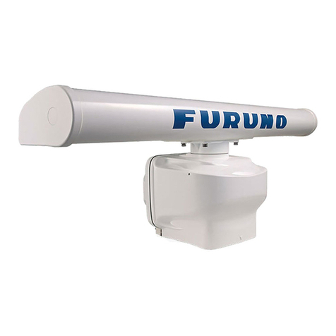
Furuno DRS4DL Manual

www.furuno.com
A
ll brand and product names are trademarks, registered trademarks or service marks of their respective holders.
Installation Manual
RADAR SENSOR
Model DRS4DL
SAFETY INFORMATION.................................................................................................. i
SYSTEM CONFIGURATION .......................................................................................... iii
EQUIPMENT LISTS........................................................................................................ iv
1. INSTALLATION.......................................................................................................... 1
1.1 Installation Considerations....................................................................................................1
1.2 Installation of the Radar Sensor............................................................................................2
2. WIRING....................................................................................................................... 7
2.1 Connections ..........................................................................................................................7
2.2 Check Points After Installation..............................................................................................7
3. MAINTENANCE, TROUBLE- SHOOTING................................................................. 9
3.1 Maintenance .........................................................................................................................9
3.2 Replacement of Fuse............................................................................................................9
3.3 Troubleshooting ..................................................................................................................10
3.4 Replacement of Magnetron.................................................................................................10
SPECIFICATIONS ..................................................................................................... SP-1
PACKING LISTS ......................................................................................................... A-1
OUTLINE DRAWING................................................................................................... D-1
INTERCONNECTION DIAGRAM ................................................................................ S-1

i
SAFETY INFORMATION
Read these safety instructions before installing or operating the equipment.
WARNING
Indicates a potentially hazardous situation
which, if not avoided, can result in minor or
moderate injury.
Warning, Caution Prohibitive Action
CAUTION
Mandatory Action
Indicates a potentially hazardous situation
which, if not avoided, can result in serious
injury or death.
Wear a safety belt and hard hat when working on the antenna unit.
Serious injury or death can result if someone falls from the radar mast.
ELECTRICAL SHOCK HAZARD
Do not open the equipment.
The installation does not require you to open the radar sensor.
Be sure the power source is compatible with the voltage rating of
the equipment.
Connection of an incorrect power source can cause fire or damage the
equipment.
Turn off the power at the power source before beginning the
installation.
Fire, electrical shock or serious injury can result if the power is left on
or is applied while the equipment is being installed.
WARNING
Do not disassemble or modify the equipment.
Fire, electrical shock or serious injury can result.
Use the proper fuse.
Use of a wrong fuse can damage the equipment or cause fire.
Do not depend one navigation device for the navigation of
the vessel.
For the safety of vessel and crew, the navigator must check all
aids available to confirm position.

SAFETY INFORMATION
ii
WARNING
The radar antenna emits electromagnetic radio frequency (RF)
energy which can be harmful, particularly to your eyes. Never
look directly into the antenna aperture from a close distance
while the radar is in operation or expose yourself to the
transmitting antenna at a close distance.
Distances at which RF radiation levels of 100, 50 and 10 W/m2exist
are given in the table below.
100 W/m210 W/m2
50 W/m2
N/A N/A 1.1 m
WARNING LABEL
A warning label is attached to the sensor. Do not remove the label.
If the label is missing or damaged, contact a FURUNO agent or dealer about
replacement.
Name: Warning Label (2)
Type: 03-129-1001-3
Code No: 100-236-743
NOTICE
Observe the following compass safe distances to prevent
interference to a magnetic compass.
It is recommended that you connect the sensor to a disconnecting
device (circuit breaker, etc.) to control the power.
Standard compass Steering compass
1.55 m 0.95 m

iii
SYSTEM CONFIGURATION
Importer in Europe
The following concern acts as our importer in Europe, as defined in DECISION No 768/2008/EC.
- Name: FURUNO EUROPE B.V.
- Address: Ridderhaven 19B, 2984 BT Ridderkerk, The Netherlands
Program No.
• 0359338-01.**
** denotes minor modifications.
CE declaration
With regards to CE declarations, please refer to our website (www.furuno.com), for further infor-
mation about RoHS conformity declarations.
Power supply
12/24 VDC
RADAR SENSOR
DRS4DL
Multi Function Display
TZTL12F/TZTL15F
* TZT9/TZT14/TZTBB
LAN
Pre-attached
power/LAN cable 1 m
: Local supply
* Software upgrade to V4 or after is required.
Selectable power/LAN cable
CP03-36400/
CP03-36410/
CP03-36420/
CP03-36430
(10/15/20/30 m)

iv
EQUIPMENT LISTS
Standard supply
Optional supply
Name Type Code No. Qty Remarks
Radar Sensor RSB-127-104 000-027-200 1
Installation Materials CP03-35701 001-265-920 1
CP03-36400 000-027-211 Select
one
Power/LAN cable 10 m
CP03-36410 000-027-212 Power/LAN cable 15 m
CP03-36420 000-027-213 Power/LAN cable 20 m
CP03-36430 000-027-214 Power/LAN cable 30 m
Spare Parts SP03-17901 001-351-470 1 Fuses
Name Type Code No. Qty Remarks
Radome Mount OP03-209 001-078-350 1

1
1. INSTALLATION
1.1 Installation Considerations
General considerations
• The radar sensor has no power switch. Therefore, it is recommended that you con-
nect the sensor to a distribution switchboard with a switch for power control.
Sensor placement
• Install the radar sensor on the hardtop, radar arch or on a mast on an appropriate
platform. (For sailboats, a “radome mount” is optionally available for fixing the sen-
sor to a mast.) Place the sensor where there is a good all-round view with, as far as
possible, no part of the ship’s superstructure or rigging intercepting the scanning
beam. Any obstruction will cause shadow and blind sectors. A mast for instance,
with a diameter considerably less than the horizontal beam width of the radiator, will
cause only a small blind sector, but a horizontal spreader or cross trees in the same
horizontal plane as the radar sensor would be a much more serious obstruction; you
would need to place the radar sensor well above or below it. Be sure there are no
metallic objects near the antenna. See illustrations below for typical placement on
a sailboat and powerboat.
NOTICE
Do not apply paint, anti-corrosive sealant or contact
spray to coating or plastic parts of the equipment.
Those items contain organic solvents that can damage
coating and plastic parts, especially plastic connectors.
Installation on a sailboat Installation on a powerboat
Typical installation on a sailboatand power boat
Radar sensorRadar sensorRadar sensor
Rear View
(Rear View)
(Rear View)
Horizontal Beam Width
12.5°
12.5°

1. INSTALLATION
2
• It is rarely possible to place the radar sensor where a completely clear view in all
directions is available. Thus, you should determine the angular width and relative
bearing of any shadow sectors for their influence on the radar at the first opportunity
after fitting.
• In order to reduce the chance of picking up electrical interference, avoid where pos-
sible routing the power cable near other electrical equipment on-board. Also, avoid
running the cable in parallel with other power cables.
• Select a location that does not allow water to accumulate at the base of the sensor.
• A magnetic compass will be affected if the radar sensor is too close to the compass.
Observe the compass safe distances mentioned in the SAFETY INFORMATION to
prevent interference to a magnetic compass.
• Do not paint the radome to ensure proper emission of the radar waves.
• When this radar sensor is to be installed on a large vessel, consider the following
points:
• The length of the standard supply power/LAN cable is 1 m (from radome to the
connector).
• The power/LAN cable runs between the radar sensor and display and comes in
lengths of 10 m, 15 m, 20 m or 30 m. Select the length when purchasing.
• Deposits and fumes from a funnel or other exhaust vent can adversely affect the
aerial performance and hot gases may distort the radiator portion. The radar sen-
sor must not be mounted where the temperature is more than 55°C (131°F).
• The radar sensor should not be operated or stored in any position other than the
proper operational position (upright).
1.2 Installation of the Radar Sensor
Determine the suitability of the mounting location BEFORE permanently mounting the
sensor. Incoming and outgoing signals may overlap one another depending on the
shape of the vessel, preventing communication between the radar and display. Set the
sensor on the selected location and connect the sensor to the distribution switchboard
and display unit. Turn on the sensor and the display unit. Check that the picture is up-
dated with each sweep on the display unit. Some trial and error may be necessary to
find a suitable location.
Required tools for installation
Prepare the tools shown below.
• A wrench for M10 bolts
• An electric drill with I11 mm (0.43”) drill bit
1. INSTALLATION
3
Installation on a platform
Follow the instructions below to install the sensor on a platform.
Note: The outer diameter of the small flat washer is the same size as the bolt hole. If
the radome is put upside down with only the small flat washer and hex bolt in place,
the hex bolt and flat washer may protrude into the radome and damage the RT unit.
For this reason, DO NOT put the radome upside down when carrying the radome.
If it is necessary to transport the radome, be sure the large flat washers are in place
before transporting, to prevent damage to the RT unit.
STERN BOW
Align bow mark (Δ) on radome
with ship’s bow.
Power/LAN cable (1 m)
Drill holes referring to the outline drawing
and the mounting template.
Platform
Hex bolt (M10×20)
Spring washer
Flat washer
Large flat washer (top)
Small flat washer
(middle)
Spring washer
(bottom)
Default position of
bolt and washer
Screw hole

1. INSTALLATION
4
1. Remove four each of hex bolts (M10u20), flat washers and spring washers pre-
attached to the bottom of the radar sensor.
2. Using the template supplied, construct a platform and drill mounting holes in the
platform to fasten the sensor. The holes must be parallel with the fore and aft line.
3. Put the radar sensor on the platform with the bow mark (U) on the sensor aligned
with the ship’s bow.
4. Use hex bolts (see the table on the next page for bolt length), flat washers and
spring washers (removed at the first step) to fasten the radar sensor to the plat-
form. The torque for the bolts is 19.6 to 24.5 N•m. Apply marine sealant (local sup-
ply) to the hex bolt.
Platform thickness and bolt to use
5. Connect the power/LAN cable pre-attached to the
radar sensor to the power/LAN cable. The connec-
tor pin assignment is as below.
Observe below guidelines for laying the power/LAN cable.
Guidelines for laying the power/LAN cable
• The connectors must not strike any part of the vessel by wind, etc.
• The load applied to the connectors must not be more than the power/LAN cable.
• If the cable is passed through a mast on a sailboat, be sure the cable does not
touch ropes (sheet, halyard, etc.).
• Do not fasten the cable to the hull.
Platform thickness Size of bolts to use
5 mm or less M10u20 (Supplied, prefastened to radome.)
6 - 10 mm M10u25 (Supplied as spare parts)
Over 10 mm Supply locally.
Hex bolt (M10×20)
Spring washer
Flat washer
×4
Platform
Sensor base
Flat washer
Hex bolt
Spring washer
Determine the length of bolts
according to platform thickness.
Marine sealant (local supply)
Connector pin assignment
17 mm

1. INSTALLATION
5
• The cable must be fixed so no tension is applied to the connectors. To prevent
tension, create a loop in the cable close to the sensor and tie the loop with cable
ties, as in the figure below.
• Wrap the junction of the connectors with self-vulcanizing tape for waterproofing.
• Fasten the cable to the mast, etc. at the neck of each connector with a cable tie.
6. Connect the power/LAN cable to the power source and display unit.
Installation with the radome mount
The optional radome mount lets you fasten the radar sensor to a mast on a sailboat.
Name, Type: Radome Mount, OP03-209
Code No.: 001-078-350
How to assemble the bracket
1. Fasten the fixing plates to brackets (1) and (2) with four M8u20 hex bolts.
2. Fit brackets (1) and (2) loosely with support plates (1) and (2) using four M4u12
hex bolts, so that the gap between the brackets can be adjusted.
3. Place the mounting plate on the bracket and fix it loosely with four M8u20 hex
bolts.
Name Type Code No. Qty
Mounting plate 03-018-9001-0 100-206-740-10 1
Support plate (1) 03-018-9005-0 100-206-780-10 1
Support plate (2) 03-018-9006-0 100-206-790-10 1
Bracket (1) 03-028-9101-1 100-206-811-10 1
Bracket (2) 03-028-9101-2 100-206-812-10 1
Fixing plate 03-028-9103-1 100-206-831-10 2
Hex bolt w/washer M8u20 SUS304 000-162-955-10 8
Hex bolt w/washer M4u12 SUS304 000-162-956-10 4
Loop cable and tie loop with cable ties.
The minimum bend diameter is 80 mm.
Wrap junction with self-vulcanizing tape
Connect cables

1. INSTALLATION
6
How to fasten the bracket to the mast
1. Drill eight holes of 6.5 mm diameter in the mast and fix the bracket with eight stain-
less steel rivets (local supply) of 6.4 mm diameter.
2. Tighten the bolts on the bracket.
3. Fasten the radar sensor to the bracket.
Connect the power cable to the power source, observing the guidelines for laying the
power cable shown on this page.
Mounting plate
Support plate (1)
Support plate (2)
Bracket (1)
Fixing plate
M8×20
ASSEMBLED RADOME MOUNT
M8×20
M8×20
M4×12
M10×25
How to fasten the sensor to the radome mount
Bracket (2)
Rivet
How to assemble the radome mount

7
2. WIRING
2.1 Connections
2.1.1 Power Requirement
The DRS4DL requires either 12 VDC or 24 VDC power. The 10/15/20 m cables are
for 12 or 24 VDC, and the 30 m cable is for 24 VDC only. Connect the red cable to the
positive terminal of ship’s battery; the blue cable to the negative terminal. The black
cable is a shielding cable for grounding.
2.1.2 LAN Cable Connection
Connect LAN cable to the multi function display device.
2.2 Check Points After Installation
Before using the product, carry out the following:
• Mechanical checks
• Turning the power on and initial setup
Mechanical checks
Check below points before switching on the DRS4DL.
• All washers are in place and bolts are fully tightened.
• All connections are secure.
• All connecting cables and wires are secured.
• LAN cable is connected to the multi function display device.

2. WIRING
8
Turning the power on and initial setup
Use the information in this manual and the manual for TZTL12F/TZTL15F/TZT9/
TZT14/TZTBB* to power the sensor and to proceed with initial setup.
* Hereafter these units are referred to as “multi function display device”.
1. Press and hold down the power key of your multi function display device until the
unit is ON. The magnetron warm-up sequence starts. When the warm-up se-
quence is completed, the unit goes into the standby mode.
2. Take the appropriate action on your multi function display device to turn on the
DRS4DL.
3. If necessary, adjust the brightness and change the language on the multi function
display device.
4. Ensure that all personnel are clear of antenna.
5. Check if the heading is correctly aligned - targets should appear at their correct
bearing relative to the boat’s bow. Adjust the alignment if necessary, referring to
installation manual of your multi function display device.
6. Check the display timing, referring to installation manual of your multi function dis-
play device.
WARNING
The radar antenna emits electro-
magnetic radio frequency (RF)
energy, which can be harmful to the
human body and interfere with pace-
maker function. Never look directly
into the antenna aperture and keep
at least 1.1 m away from the radar
antenna while the radar is in operation.

9
3. MAINTENANCE, TROUBLE-
SHOOTING
3.1 Maintenance
Regular maintenance is important for good performance. Check the points mentioned
below every 3 to 6 months to keep the radar sensor in good working order. Observe
the safety instructions at the front of this manual when working on the mast.
3.2 Replacement of Fuse
The 5A fuse (Type: FRU-2P5S-FU-5A-A, Code No.: 000-168-869-10) in the fuse hold-
er on the power/LAN cable protects the radar sensor from overcurrent and equipment
fault. If you cannot turn on the power, check the fuse to see if it has blown. If the fuse
has blown, find the reason before you replace the fuse. If the fuse blows again after
the replacement, contact your dealer for advice.
Check point Action
Fixing bolts
• Corrosion
• If they are tightly fastened
• Replace corroded bolts.
• Tighten loosened bolts.
• Coat new bolts with marine sealant.
Radome
• Cracks
• Foreign material
If a crack is found, repair it temporarily with a small
amount of sealing compound or adhesive. Bring the unit
to your dealer for permanent repairs.
Foreign material on the radome can cause a consider-
able drop in sensitivity. Remove foreign material with a
freshwater-moistened cloth. Do not use commercial
cleaners to clean the sensor; they can remove paint and
markings or deform the plastic.
WARNING
Use the proper fuse.
Use of the wrong fuse can damage the equip-
ment or cause fire.
WARNING
DO NOT OPEN THE SENSOR.
Electrical shock hazard
There are no user-serviceable parts
inside. Only qualified personnel are
allowed to work inside the equipment.

3. MAINTENANCE, TROUBLE- SHOOTING
10
3.3 Troubleshooting
The table below provides simple troubleshooting procedures to restore normal opera-
tion. If you cannot restore normal operation, contact your dealer for advice.
3.4 Replacement of Magnetron
The life expectancy of the magnetron is approx. 5,000 hours (including standby). The
effectiveness of the magnetron decreases over time, causing lower-than-normal sig-
nal strength and loss of echoes. If you feel the signal strength is low, contact your deal-
er about replacement of the magnetron.
Trouble Remedy
The power cannot be turned on. • Check if the power/LAN cable is connected to
the power source and the power source is on.
• Check the power cable for damage.
• Check if the fuse has blown.
Picture is not updated or the picture
freezes.
• Check antenna cable.
• If the picture freezes, reboot the display unit.
Marks and characters appear on
the display, but echoes do not ap-
pear.
Check that the antenna cable is fastened.
You changed the range, but the ra-
dar picture does not change.
• Try to zoom in or out the radar display.
• Turn the power off and on.
Signal strength is too low. Have a technician check the magnetron.
Name Type Code No.
Magnetron E3571 (80-0691) 001-266-460

FURUNO
DRS4DL
SP - 1 E3637S01C
161219
SPECIFICATIONS OF RADAR SENSOR
DRS4DL
1 RADIATOR
1.1 Antenna type Patch array antenna
1.2 Antenna length 19-inch
1.3 Horizontal beam width 5.2° typical (3 dB)
1.4 Vertical beam width 25° (3 dB)
1.5 Sidelobe attenuation -20 dB (within ±20°), -25 dB (±20° or more)
1.6 Rotation 24 rpm
2 RADAR FUNCTION
2.1 Tx frequency 9410±30 MHz, P0N
2.2 Output power 4 kW
2.3 Duplexer Ferrite circulator
2.4 Intermediate frequency 60 MHz
2.5 Range, Pulse length and Pulse repetition rate
Range (NM) Pulse length (Ps) PRR (Hz approx.)
0.125 to 0.5 0.08 360
0.75 to 2 0.3 360
3 to 36 0.8 360
2.6 Minimum range 25 m
2.7 Range resolution 25 m
2.8 Range accuracy 1 % of range in use or 0.01 NM, which is the greater
2.9 Bearing resolution 5.2°
2.10 Bearing accuracy ±1°
2.11 Warming up time 90 s
3 INTERFACE
LAN 1 port, Ethernet 100Base-T, RJ45
4 POWER SUPPLY
12-24 VDC: 2.1-1.0 A
5 ENVIRONMENTAL CONDITIONS
5.1 Ambient temperature -25°C to +55°C (storage: +70°C or less)
5.2 Relative humidity 95% or less at +40°C
5.3 Degree of protection IP26
5.4 Vibration IEC 60945 Ed.4
6 UNIT COLOR
N9.5 (cover), 2.5PB3.5/10 (bottom)

㹎㹎㸿㹁㹉㹇㹌㹅ࠉ㹊㹇㹑㹒
+3;
''56'/1
1$0(
287/,1(
'(6&5,37,21&2'(θ
47<
ࣘࣘࢽࢵࢺ
881,7
㺸㺎㺞㺼㺎㺜㺻㺙㺎
5$'$56(1625
56%
ணணഛရ
663$5(3$576
ணഛရ
63$5(3$576
63
ᕤᕤᮦᩱ
,,167$//$7,210$7(5,$/6
ᕤᮦᩱ
,167$//$7,210$7(5,$/6
&3
ᅗᅗ᭩
''2&80(17
ᆺ⣬
7(03/$7(
(
ഛせ㡿᭩ⱥ
,167$//$7,210$18$/(1
,0(
䡶㻙䢀䢚␒ྕᮎᑿ䛾㼇㻖㻖㼉䛿䚸㑅ᢥရ䛾௦⾲䡶䡬䢀䢚䜢⾲䛧䜎䛩䚹
㻯㻻㻰㻱㻌㻺㼁㻹㻮㻱㻾㻌㻱㻺㻰㻵㻺㻳㻌㼃㻵㼀㻴㻌㻎㻖㻖㻎㻌㻵㻺㻰㻵㻯㻭㼀㻱㻿㻌㼀㻴㻱㻌㻯㻻㻰㻱㻌㻺㼁㻹㻮㻱㻾㻌㻻㻲㻌㻾㻱㻼㻾㻱㻿㻱㻺㼀㻭㼀㻵㼂㻱㻌㻹㻭㼀㻱㻾㻵㻭㻸㻚
䠄␎ᅗ䛾ᑍἲ䛿䚸ཧ⪃್䛷䛩䚹㻌㻌㻰㻵㻹㻱㻺㻿㻵㻻㻺㻿㻌㻵㻺㻌㻰㻾㻭㼃㻵㻺㻳㻌㻲㻻㻾㻌㻾㻱㻲㻱㻾㻱㻺㻯㻱㻌㻻㻺㻸㼅㻚䠅
C3637-Z01-B
A
-1

%
%1&'01
6;2'
%2
⇛ޓޓ࿑
176.+0'
ฬޓޓ⒓
0#/'
ᢙ㊂
36;
↪ㅜ㧛⠨
4'/#4-5
⇟ภ
01
ဳฬ㧛ⷙᩰ
&'5%4+26+105
+056#..#6+10/#6'4+#.5
Ꮏ᧚ᢱ
*0:
㩚㩀㩨㩁ᐔᐳ㊄
(.#69#5*'4 /575
%1&'01
㩔㩨㩒ᐳ㊄
524+0)9#5*'4 /575ޓ
%1&'01
ⷺ㩇㩢㩦㩢㩘㩨㩣㩎
*':$1.65.166'&
*'#&
/:575
%1&'01
㧔⇛࿑ߩኸᴺߪޔෳ⠨୯ߢߔޕޓ&+/'05+105+0&4#9+0)(144'('4'0%'10.;㧕
㧲㨁㧾㨁㧺㧻ޓ㧱㧸㧱㧯㨀㧾㧵㧯ޓ㧯㧻ޓ㧚㧘㧸㨀㧰
ဳᑼ㩄㨺㩎㩨⇟ภ߇㧞Ბߩ႐วޔᲑࠃࠅᲑߦઍࠊࠆㆊᦼຠߢࠅޔߤߜࠄ߆߇ߞߡ߹ߔޕޓߥ߅ޔຠ⾰ߪᄌࠊࠅ߹ߖࠎޕ
6916;2'5#0&%1&'5/#;$'.+56'&(14#0+6'/6*'.19'4241&7%6/#;$'5*+22'&+02.#%'1(6*'722'4241&7%6
37#.+6;+56*'5#/'
%/#
A
-2
%
%1&'01
6;2'
52
+6'/
01
0#/'1(
2#46 176.+0'
&9)01
14
2'4
5'6
2'4
8'5
52#4'
914-+0)
37#06+6; 4'/#4-5%1&'01
$1:012
5*+201
52#4'2#465.+56(14 75'
5'652'4
8'55'.
6;2'01
*2:
㩕㨷㨺㩇㩨
(4725(7
#$
(75'
/(450#/'
(74701'.'%64+%%1.6&
&9)01
㧔⇛࿑ߩኸᴺߪޔෳ⠨୯ߢߔޕޓ&+/'05+105+0&4#9+0)ޓ(144'('4'0%'10.;㧕
%2$
ဳᑼ㩄㨺㩎㩨⇟ภ߇㧞Ბߩ႐วޔᲑࠃࠅᲑߦઍࠊࠆㆊᦼຠߢࠅޔߤߜࠄ߆߇ߞߡ߹ߔޕޓߥ߅ޔຠ⾰ߪᄌ
ࠊࠅ߹ߖࠎޕ
6916;2'5#0&%1&'5/#;$'.+56'&(14#0+6'/6*'.19'4241&7%6/#;$'5*+22'&+02.#%'1(6*'
722'4241&7%637#.+6;+56*'5#/'
A
-3

D-1
1/Feb/2017 H.MAKI
1/Feb/2017 H.MAKI

S-1
Table of contents
Other Furuno Accessories manuals

Furuno
Furuno Precision PG-500 User manual

Furuno
Furuno PG-700 User manual

Furuno
Furuno FI-3002 User manual

Furuno
Furuno DRS4DL+ User manual

Furuno
Furuno FI-3003 User manual

Furuno
Furuno DRS6A X-Class User manual

Furuno
Furuno FELCOM 16 User manual

Furuno
Furuno Precision PG-500 Manual

Furuno
Furuno PG-1000 User manual

Furuno
Furuno DRS12A X-Class User manual