Mandatory Action
Prohibitive Action
WARNING
CAUTION
Warning, Caution
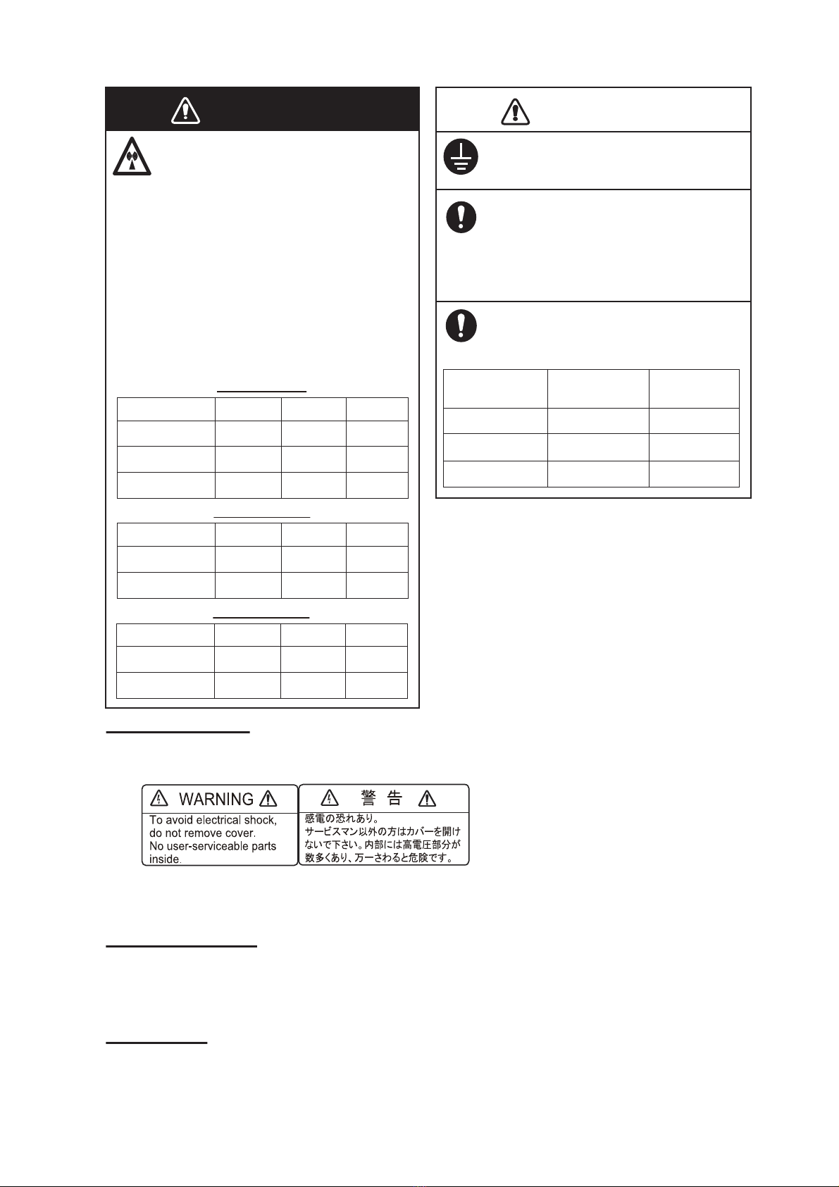
WARNING
The installer of the equipment must read the safety instructions before attempting to
install the equipment.
Indicates a potentially hazardous situation which, if not avoided,
could result in death or serious injury.
Indicates a potentially hazardous situation which, if not avoided,
can result in minor or moderate injury.
WARNING
Turn off the power at the
switchboard before beginning the
installation.
Fire or electrical shock can result if
the power is left on.
Do not open the equipment
unless you are well familiar with
electrical circuits.
Only qualified personnel should
work inside the equipment.
Be sure that the power supply is
compatible with the voltage rating
of the equipment.
Connection of an incorrect power
supply can cause fire or damage the
equipment.
Use only the specified power and
signal cable.
Fire or damage to the equipment
can result if a different cable is used.
Wear a safety belt and hard hat
when working on the antenna
unit.
Serious injury or death can result if
someone falls from the radar mast.
Do not disassemble or modify the
equipment.
Fire, electrical shock or serious
injury can result.
Construct a suitable service
platform from which to install the
antenna unit.
Serious injury or death can result if
someone falls from the radar mast.
Keep the objects away from the
antenna unit, so as not to impede
rotation of the antenna.
Fire, electrical shock or serious
injury can result.
Use the proper fuse.
Use of a wrong fuse can damage
the equipment or cause fire.
Do not depend one navigation
device for the navigation of the
vessel.
For the safety of vessel and crew,
the navigator must check all aids
available to confirm position.