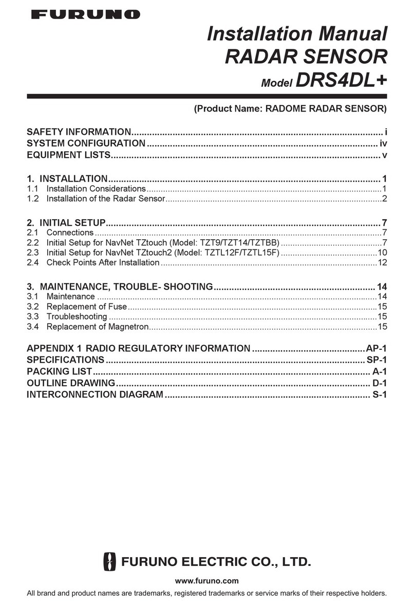
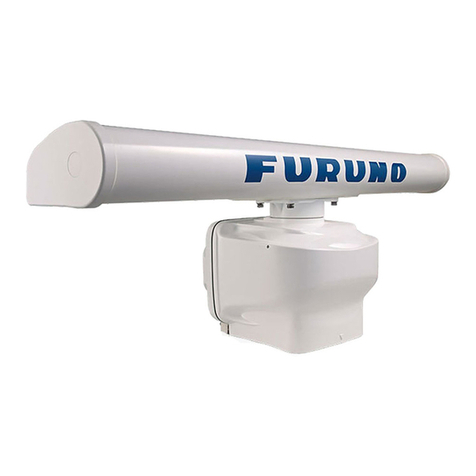
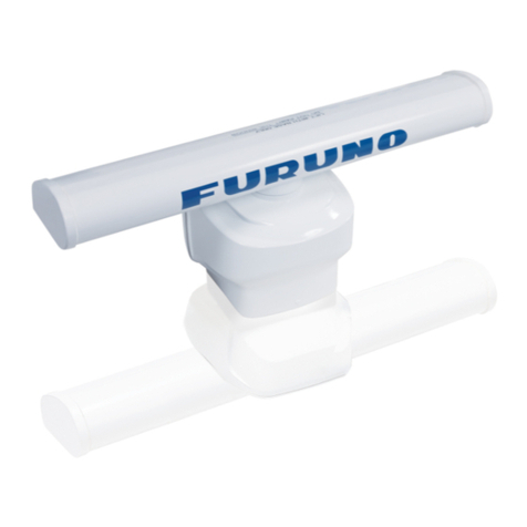
Furuno DRS4D User manual

www.furuno.com
A
ll brand and product names are trademarks, registered trademarks or service marks of their respective holders.
Installation Manual
RADAR SENSOR
Model DRS4D X-Class
SAFETY INFORMATION.................................................................................................. i
SYSTEM CONFIGURATION .......................................................................................... iv
EQUIPMENT LISTS......................................................................................................... v
1. INSTALLATION.......................................................................................................... 1
1.1 Installation Considerations....................................................................................................1
1.2 Necessary Tools and Materials.............................................................................................3
1.3 Installation of the Antenna Unit (Radar Sensor) ...................................................................4
2. INITIAL SETUP........................................................................................................... 9
2.1 Connections..........................................................................................................................9
2.2 Checks After Installation .......................................................................................................9
3. MAINTENANCE, TROUBLESHOOTING ................................................................. 12
3.1 Maintenance .......................................................................................................................12
3.2 Troubleshooting ..................................................................................................................13
3.3 Replacement of Fuse..........................................................................................................14
3.4 Replacement of Parts .........................................................................................................14
PACKING LIST(S) ....................................................................................................... A-1
OUTLINE DRAWING(S) .............................................................................................. D-1
INTERCONNECTION DIAGRAM(S) ........................................................................... S-1

FURUNO Authorized Distributor/Dealer
Printed in Japan
(Elemental Chlorine Free)
The paper used in this manual
is
elemental chlorine free.
9-52, Ashihara-cho,
Nishinomiya, 662-8580, JAPAN
All rights reserved.
Pub. No. IME-36890-Z
(DAMI) DRS4D_X-Class
Z : OCT. 2021

i
SAFETY INFORMATION
WARNING
Indicates a condition that can cause death or serious
injury if not avoided.
CAUTION
Indicates a condition that can cause minor or moderate
injury if not avoided.
Warning, Caution Mandatory Action
Prohibitive Action
Read these safety instructions before you operate or install the equipment.
WARNING
Radio Frequency Radiation Hazard
The radar antenna sends the electromagnetic
radio frequency (RF) energy. This energy can
be dangerous to you, especially your eyes.
Do not look at the radiator or near the
antenna when the antenna is rotating.
The distances at which RF radiation levels of
100 W/m2, 50 W/m2and 10 W/m2exist are
shown in the table below.
Note: If the antenna unit is installed at a
close distance in front of the wheel house,
prevent the transmission in that area to
protect passengers and crew from microwave
radiation. See Sector Blanking in chapter 2.
Distance to
100 W/m2
point
Distance to
50 W/m2
point
Distance to
10 W/m2
point
1.7 m
WARNING
Do not disassemble or modify the
equipment.
Fire, electrical shock or serious injury
can result.
To prevent falls when working at
heights, secure a service scaffolding
or landing at the installation location
of the antenna.
For the power supply, use a voltage
suitable for the rated voltage of the
device.
Using a voltage outside the rated
voltage may cause a fire or equipment
failure.
Turn off the power at the switch-
board before beginning the installa-
tion.
If the work is done with the power
turned on, there is a risk of electric
shock or fire.
If the equipment is giving off smoke
or fire, immediately turn off the
power at the switchboard.
Fire or electrical shock can result.
Use the specified connection cables
and fuses.
Use of other cables or fuses may cause
a serious accident or fire.
If water leaks into the equipment
turn off the power at the switch-
board.
Fire, electrical may result.
0.53 mN/A
Do not open the equipment.
The equipment uses high voltage that
can cause electrical shock. Refer any
repair work to a qualified technician.
Wear a safety belt and hard hat
when working on the antenna unit.
Serious injury or death can result if
someone falls from the radar mast.

SAFETY INFORMATION
ii
CAUTIONCAUTION
The data presented by this equipment
is intended as a source of navigation
information.
The prudent navigator never relies
exclusively on any one source of
navigation information, for safety of vessel
and crew.
Observe the following compass safe
distances to prevent interference to a
magnetic compass.
WARNING
The TT function is a valuable aid to
navigation. However, the navigator
must check all aids available to avoid
collision.
- The TT automatically tracks an
automatically or manually acquired
radar target and calculates its course
and speed, indicating them with a
vector. Since the data generated by
the TT depends on the selected radar
targets, the radar must be optimally
tuned for use with the TT, to ensure
required targets will not be lost or
unnecessary targets, like sea returns
and noise, will not be acquired and
tracked.
- A target is not always a landmass,
reef, ship, but can also be returns
from the sea surface and from clutter.
As the level of clutter changes with
the environment, the operator must
correctly adjust the sea and rain
clutter controls and the gain control so
that the target echoes do not dis-
appear from the radar screen.
Target Tracking (TT) safety information
CAUTIOCAUTION
The plotting accuracy and response of this
TT meets IMO standards. Tracking accuracy
is affected by the following:
• Tracking accuracy is affected by course
change. One to two minutes is required to
restore vectors to full accuracy after an
abrupt course change. (The actual amount
depends on gyrocompass specifications.)
•The amount of tracking delay is inversely
proportional to the relative speed of the
target. Delay is approx. 15-30 seconds for
the higher relative speed; approx. 30-60
seconds for the lower relative speed. The
following factors can affect accuracy:
- Echo intensity
- Radar transmission pulse length
- Radar bearing error
- Heading sensor error
- Course change (own ship and targets)
Standard
Compass
Steering
Compass
Antenna unit 1.70 m 1.05 m
Unit
CAUTIONCAUTION
Install the antenna where only
technicians can access it, such as the
radar mast.
To turn the power of this unit on or
off, connect it to the onboard power
supply via a disconnection device
such as a breaker.
Ground the equipment.
Poor grounding can cause interference
from other equipment or interfere with
other equipment.
Follow the instructions in this manual
to ensure that the equipment is
properly installed and that all related
equipment is properly connected.
In some countries a radio license is
required to install a radar.
For details, contact a FURUNO agent or
dealer.
Do not use high-pressure
cleaners to clean this equipment.
This equipment has the waterproof
rating outlined in the equipment
specifications. However, the use of
high-pressure cleaning equipment can
cause water ingress, resulting in damage
to, or failure of, the equipment.
SAFETY INFORMATION
iii
Name: Warning Label (2)
Type: 03-129-1001-3
Code No.: 100-236-743
Warning Label(s)
Warning label(s) is(are) attached to the equipment. Do not remove the label(s).
If a label is missing or damaged, contact a FURUNO agent or dealer about replacement.
Importer in Europe
The following concern acts as our importer in Europe, as defined in
DECISION No 768/2008/EC.
- Name: FURUNO EUROPE B.V.
- Address: Ridderhaven 19B, 2984 BT Ridderkerk, The Netherlands
Program No.
• 0
359517-01
.**
** Denotes minor modifications.
CE declarations
With regard to CE declarations, please refer to our website (www.furuno.com),
for further information about RoHS conformity declarations.
Importer in UK
The following concern acts as our importer in UK, as defined in SI 2016/1025
as amended SI 2019/470.
- Name: FURUNO (UK) LTD.
- Address: West Building Penner Road Havant Hampshire PO9 1QY, U.K.

iv
SYSTEM CONFIGURATION
Power Supply
12-24 VDC
RADAR SENSOR
DRS4D X-Class
Marine Radar (Display Unit)
FR-10/12
LAN cable
Power/LAN cable (1 m, pre-attached)
Cable Assy.
FRU-2P5S-FF-10M-A (10 m) /
FRU-2P5S-FF-15M-A (15 m) /
FRU-2P5S-FF-20M-A (20 m) /
FRU-2P5S-FF-30M-A (30 m)
Distribution
Switchboard
Ethernet
HUB-101
Sub Display,
LAN compatible
chart plotter
: Standard supply:
: Option, or local supply
TZTL12F/TZTL15F/TZT2BB
*1
TZT9F/TZT12F/TZT16F/TZT19F
*2
*1
: Software version 8.01 or higher (scheduled)
*2
: Software version 3.01 or higher (scheduled)
Note: When using the EMC Modification Kit
(OP03-259), refer to the power/LAN cable
replacement instructions (C32-01803),
included with the kit.

v
EQUIPMENT LISTS
Standard supply
Optional supply
Name Type Code No. Qty Remarks
Radar Sensor RSB-143-128 - 1
Installation Materials CP03-37001 001-552-170 1
CP03-38500 000-035-186
Select
one
Power/LAN cable 10 m
CP03-38510 000-035-187 Power/LAN cable 15 m
CP03-38520 000-035-188 Power/LAN cable 20 m
CP03-38530 000-035-189 Power/LAN cable 30 m
Spare Parts SP03-19401 001-552-160 1 Fuses (FRU-60C-FU-5A)
Installation Guide J32-02105-A 000-199-071 1
Template C32-00702-* 000-167-458 1
Name Type Code No. Remarks
Joint Box
Note: After connecting, wrap with
self-bonding tape and vinyl tape to
protect the connector joints from
water ingress.
TL-CAT-012 000-167-140 For LAN cable
extension
LAN Cable MOD-Z072-020+ 000-167-880 2 m
MOD-Z072-050+ 000-167-890 5 m
MOD-Z072-100+ 000-167-900 10 m
EMC Modification Kit OP03-259-1 001-524-010 w/10 m cable
OP03-259-2 001-524-020 w/15 m cable
OP03-259-3 001-524-030 w/20 m cable
OP03-259-4 001-524-040 w/30 m cable
Radome Mount OP03-208 001-078-340
Retractable Mast
Waterproofing Kit

1
1. INSTALLATION
1.1 Installation Considerations
• To ensure proper emission of radar waves, do not paint the radome.
• Install the unit on a common mast, radar mast, etc.
• Make sure the mounting location does not allow water to accumulate on the mount-
ing platform.
• Do not cut the power/LAN cable.
Distribution switchboard
This antenna unit does not have a power switch. Connect to the onboard power supply
via a distribution switchboard so that the power to the antenna unit can be turned on/
off.
Mounting position
• The antenna unit is mounted on a radar arch, a common mast or radar mast, a ded-
icated mounting base, etc.
For installation on a sailboat, use the optional radome mount.
• Install the antenna unit in a place with a good view as much as possible and no ob-
struction around the unit. Select a place where there is no chimney or mast in the
bow direction. If there are obstacles, a blind spot for radio waves will occur and no
images will appear on the display in that area. In addition, the performance of the
antenna unit (beam width and side lobe level) may be reduced, and false images
may appear. A mast with a diameter smaller than the radiation width of the antenna
unit will produce a small blind spot, but if there is a horizontal plane at the same
height as the antenna unit, a large blind spot will result. Choose a position that is
well above the horizontal plane.
• Select a location near the radar (within 1 m in diameter) where there are no large
structures such as masts.
NOTICE
Do not use paint, anti-corrosion products, contact spray or other
items containing organic solvents on the equipment.
Organic solvents can harm paint and plastic, particularly the connectors.
(a) Common mast (b) Radar mast

1. INSTALLATION
2
• It is almost impossible to install the antenna unit in a place where there are no ob-
stacles all around. When checking the operation, check if there is a blind spot. if
there is a blind spot, note the direction.
• Avoid mounting directly above the cabin where crew (occupants) are present, as the
motor drive noise of the antenna may echo inside the cabin.
• Observe the compass safe distances mentioned in the safety instructions, to pre-
vent interference to a magnetic compass.
• Referring to the outline drawings at the back of this manual, allow space for main-
tenance and service.
• The antenna unit should not be operated or stored in any position other than the
proper operational position (upright).
• Use the optional waterproof kit when using a retractable mast.
Installation on a sailboat Installation on a powerboat
Radar sensorRadar sensorRadar sensor
Rear View
(Rear View)
(Rear View)
Horizontal Beam Width
12.5°
12.5°
Not recommended

1. INSTALLATION
3
Installation with radio equipment
• Install the antenna unit away from radio antennas (SSB, VHF, Inmarsat) and GPS
antenna.
• Install the antenna unit away from radio receivers to prevent electromagnetic inter-
ference to the radio.
Cabling
• To prevent noise, do not lay the cables of this unit near or in parallel with the power
cables of other electronic devices.
• When laying the cable of the antenna unit in parallel with the cables of radio equip-
ment, use the cable supplied with the EMC Modification Kit and separate all cables
at least 1.5 m from one another.
• Be sure that the power/LAN cable and cable assembly are not run parallel to each
other. Also, locate those cables well away from other signal cables and antennas.
Installation on large vessels
• The antenna unit cable comes in lengths of 10, 15 and 20 m (30 m optionally avail-
able). Consider the length of the cable when selecting a mounting location.
• Keep the unit away from smoke and exhaust stacks. Hot air affects antenna perfor-
mance. Hot air can also damage the unit. The temperature at the mounting location
should not exceed 55°C (131°F).
1.2 Necessary Tools and Materials
The following tools are necessary to complete the instal-
lation.
*: For aesthetic reasons, it is recommended to use the
same color (black) tape as the cable.
Name Usage
Electric drill Drill holes for mounting. Drill bit: 11 mm
Hexagonal wrench For fastening bolts (M10).
Self-bonding tape* For waterproofing connector junction.
Vinyl tape*
Cable tie For securing cable.

1. INSTALLATION
4
1.3 Installation of the Antenna Unit (Radar Sensor)
How to fasten the antenna unit to the mounting platform
Referring to the figure below, fasten the antenna unit to the mounting platform.
1. Use the mounting template (supplied) to mark the location of fixing holes in the
mounting platform. Be sure to drill the holes parallel with the bow.
2. Lay the antenna unit on the mounting platform with the bow mark () on the an-
tenna unit facing the bow.
STERN
Align bow mark (Δ)
on antenna with
boat’s centerline.
Power/LAN cable (1 m)
Drill holes referring to the outline drawing
and the mounting template.
Mounting platform
Hex bolt (M10 × **)
Spring washer
Flat washer
Flat washer (M10)
Spring washer
**: Bolt length. See table on
next page for details.
BOW
Positional relationship
between bolt and flat
washer
Note: Thistemplate may have expanded or shrunk slightly.
Pleaseconfirm dimensions before use.
ὀព㻦㻌㻌ᮏᆺ⣬䛿ಖᏑ≧ែ䛻䜘䜚ⱝᖸఙ⦰䛩䜛ሙྜ䛜䛒䜚䜎䛩䚹
㻌㻌㻌㻌㻌㻌㻌㻌㻌⏝䛾㝿䛻䛿ᑍἲ䜢☜ㄆ䛧䛶䛟䛰䛥䛔䚹㻌
Drill 11mm (0.43'') holein dia. (four positions)
䃥㻝㻝㼙㼙㻌䜻䝸㻌㻔㻠䞃ᡤ㻕
㻝㻢㻜㼼0.5mm (6.3'')
㻝㻢㻜㼼0.5mm(6.3'')
㻢㻜mm (2.36'')
CENTEROF ANTENNA ROTATION
䜰䞁䝔䝘ᅇ㌿୰ᚰ
BOW
⯪㤳᪉ྥ
December 2014 PrintedinJapan
C32-00702-A1
㻰㻾㻿䝅䝸䞊䝈䝺䝗䞊䝮䝉䞁䝃䞊
ᆺ⣬
DRS Series Radome Sensor
Template
䢲䢲䢲䢳䢸䢹䢶䢷䢺䢳䢲
BOW
BOW
Template

1. INSTALLATION
5
3. Use the installation materials (CP03-37001), consisting of hex bolts*, flat washers
and spring washers), to fasten the antenna unit to the platform. The torque for the
bolts must be 19.6 to 24.5 Nm. Apply marine sealant (local supply) to the hex
bolts, flat washers and spring washers as shown below.
*: See the table below to determine the bolt length to use.
Platform thickness and bolt to use
4. Connect the power/LAN cable from the antenna unit. The
connector pin arrangement is as shown to the right.
Observe the below guidelines for laying the power/LAN
cable.
• Do not fasten the cable to the hull.
• If radar noise is interfering with VHF radio equipment,
use the cable supplied with the EMC Modification Kit in place of the LAN/power
cable, and separate the cable at least 1.5 m from the radio cable.
• Make sure the cable connector does not strike the hull because of wind, etc.
• If the cable is passed through a mast on a sailboat, be sure the cable does not
touch ropes (sheet, halyard, etc.).
• The cable must be secured so no tension is applied to its connectors. As shown
in the figure below, create a loop in the cable close to the unit and secure the
loop with cable ties.
Platform thickness Size of bolts to use
6 to 10 mm M1025 (Supplied as installation material)
Over 10 mm Supply locally.
Mounting platform
Antenna unit base
Flat washer
Hex bolt
Spring washer
Determine the length of bolts
according to platform thickness.
Marine sealant (local supply)
Pin arrangement
10 mm
Loop cable and secure loop with cable ties.
The minimum bend radius is 242 mm.

1. INSTALLATION
6
• For waterproofing, wrap the junction of the connectors with self-bonding tape
and vinyl tape.
5. Insert a fuse in the fuse holder on the cable, referring to the instructions “HOW TO
ATTACH THE FUSE” (C32-01604-**), supplied with the cable. Attach the supplied
fuse rating label (5A) on the fuse holder cover.
6. Connect the LAN connector of the cable to the LAN port of FR-10/12, TZTL12F/
TZTL15F/TZT2BB, TZT9F/TZT12F/TZT16F/TZT19F, or the Ethernet Hub. Do not
connect to the onboard LAN.
Self-bonding tape
1) Wind one layer of the self-bonding tape
around the connector joint.
2) Change the winding direction and wind
one layer of the self-bonding tape again.
Self-bonding tape
3) Wind one layer of the vinyl tape over the
self-bonding tape.
Vinyl tape
4) Change the winding direction and
wind one layer of vinyl tape again.
Vinyl tape
Cable assy.
LAN connector
Ethernet Hub
OR
䠢䠮-10/12
TZTL12F/TZTL15F/TZT2BB,
TZT9F/TZT12F/TZT16F/TZT19F
OR

1. INSTALLATION
7
7. Connect the power wires to the ship’s battery (12 VDC or 24 VDC).
• Red wire: Connect to the positive (+) terminal. The red wire has the fuse holder.
• Blue wire: Connect to the negative (–) terminal.
• Black wire: The black wire is a shielding wire for grounding.
Note 1: There is no power switch on the antenna unit. Connect to the onboard
power supply via a distribution switchboard so that you can power the antenna
unit on and off. Even when the power to the display unit (FR-10/12, TZTL12F/TZ-
TL15F/TZT2BB, TZT9F/12F/16F/19F) is turned off, standby power (13W) is gen-
erated because the power is supplied to the antenna unit. Be sure to turn off the
breaker if you do not use the radar when powering from the battery.
Note 2: The antenna unit cannot accept input voltage of more than 24 VDC.
Radome mount
The optional radome mount is for installing the antenna unit on a mast on a sailboat.
Name, Type: Radome Mount, OP03-208
Code No.: 001-078-340
Name Type Code No. Qty
Mounting Plate 03-018-9001-0 100-206-740 1
Bracket (1) 03-018-9005-0 100-206-780 1
Bracket (2) 03-018-9006-0 100-206-790 1
Support Plate (1) 03-028-9002-3 100-206-753 1
Support Plate (2) 03-028-9003-3 100-206-763 1
Fixing Plate 03-028-9004-3 100-206-773 2
Hex Bolt B M820 SUS304 000-162-955 10
Hex Bolt B M412 SUS304 000-162-956 4
LAN cable
To antenna unit
Cable assy.
Shield
Distribution
Switchboard
Ship's battery
(12 VDC /
24 VDC)
Blue
Black
Fuse holder
Red

1. INSTALLATION
8
How to assemble the bracket:
1. Fasten the fixing plates to brackets (1) and (2) with four M820 hex bolts.
2. Using four M412 hex bolts, loosely fasten support plates (1) and (2) to brackets
(1) and (2), so that the gap between the brackets can be adjusted later.
3. Place the mounting plate on the brackets and loosely fasten it with four M820 hex
bolts.
How to fasten the radome mount to the mast:
1. Drill eight holes of 6.5 mm diameter in the mast. Fasten the bracket to the mast
with eight stainless steel rivets (local supply) whose diameter is 6.4 mm.
2. Tighten the bolts on the bracket.
3. Fasten the antenna unit to the bracket with four sets of flat washers, split washers,
and bolts (M1025).
Mounting plate
(1)
M8×20
M8×20
M8×20
M4×12
(2)
Radome mount (assembled)
Bracket (1)
Support plate (2)
Support plate (1)
Fixing plate
Mounting plate
Bracket (2)
M10×25
Rivet

9
2. INITIAL SETUP
2.1 Connections
2.1.1 Power requirements
The antenna unit requires either 12 VDC or 24 VDC power. Connect the red cable of
the cable assembly to the positive terminal of the distribution switchboard and the blue
wire to the negative terminal of the distribution switchboard. The black wire is a shield-
ed wire; connect it to the hull ground.
2.1.2 LAN cable connection
Connect the LAN cable to the display unit (FR-10/12, TZTL12F/TZTL15F/TZT2BB,
TZT9F/12F/16F/19F) or the Ethernet Hub HUB-101.
2.2 Checks After Installation
Do the following before using the equipment.
• Perform a mechanical inspection.
• Power the unit and make the initial settings.
Mechanical inspection
Check the following before powering the equipment.
• All flat washers are in the correct position and tightly fastened.
• All connection points are correctly connected.
• All cables are connected.
• The LAN cable is connected to the display unit (FR-10/12, TZTL12F/TZTL15F/
TZT2BB, TZT9F/12F/16F/19F).

2. INITIAL SETUP
10
Initial setup
Refer to the information described in this manual and the manual of the display unit
(FR-10/12, TZTL12F/TZTL15F/TZT2BB, TZT9F/12F/16F/19F) to do the initial setup.
1. Power the radar sensor and the display unit. Warm up of the magnetron begins.
2. If communication between the display unit and this unit is established, a count-
down or "preparation" appears on the display. If not displayed, check that the ra-
dar sensor is connected to the display unit and that the settings on the display unit
are correct (see the operator’s manual for the display unit).
3. Transmit and confirm that radar echoes appear on the display.
• If the FR-10/12 is connected as a display unit, set the following items. For other
display units, confirm and set the antenna rotation speed, align the heading,
suppress the main bang, set sector blanking area(s), set the tuning mode, and
tune the radar manually. See the display unit’s installation manual for the pro-
cedure.
([Installation Setup] menu)
Note: The items on the [Installation Setup] menu come into effect after completing
the following settings.
1) Press the [MENU] key to open the menu.
2) While pressing and holding down the [ESC/HL OFF] key, press the [MENU]
key five times.
([Sector Blanking] menu)
([Tuning/TX Channel] menu)
Menu item Description
[Antenna Rotation] Set the antenna rotation speed (Settings: Auto, 24 rpm).
[Antenna Heading Align] See “How to align the antenna heading.”
• Make sure the heading line is displayed in the correct
direction. Check that targets are displayed in the cor-
rect direction with respect to the bow.
[Sweep Timing] Adjust the sweep timing (Setting range: -10 to 10).
[Main Bang Suppression] If main bang appears at the screen center, slide the cir-
cle icon, while watching the radar echo on the left-side
of the display, until the main bang disappears.
Menu item Description
[Enable Sector Blanking 1],
[Enable Sector Blanking 2]
Up to two sectors may be set for blanking (no transmis-
sion). Select [ON] to enable this feature. Set the start
and end angles (0° to 359°).
Menu item Description
[Tuning Mode] Set the tuning mode, automatic or manual, for the con-
nected radar
[Manual Tuning] Manually tune the radar. Not available when [Tuning
Mode] is [Auto].
[Tuning Initialization] If the radar cannot be tuned, initialize tuning.

2. INITIAL SETUP
11
How to align the antenna heading
You have mounted the antenna unit facing straight ahead in the direction of the bow.
Therefore, a small but conspicuous target dead ahead visually should appear on the
heading line (zero degrees).
You may observe a minor bearing error on the display. This is due to the difficulty in
orienting the antenna unit accurately. The following adjustment will compensate for
the error.
1. Select a range between 0.125 and 0.25 NM and set the mode to “head up”.
2. Turn the vessel’s bow toward a target.
3. Press the [MENU] key to open the menu.
4. While pressing and holding down the [ESC/HL OFF] key, press the [MENU] key
five times.
5. Open the [Installation Setup] menu.
6. Select [Antenna Heading Align].
7. Key in an offset value so that the target is at the very top of the screen (setting
range: 0.0° to 359°) then press the [ENT] key. Enter a plus value if the deviation
is clockwise; minus value if the deviation is counterclockwise.
8. Confirm that the target echo is displayed at correct bearing on the screen.
Correct
position
of target Apparent
position
of target
Target
Picture appears deviated clockwise
(enter plus offset value)
Picture appears deviated counterclockwise
(enter minus offset value)
Antenna installation error
(deviated to starboard)
Antenna installation error
(deviated to port)
Target
Correct
position
of target
Apparent
position
of target

12
3. MAINTENANCE,
TROUBLESHOOTING
This chapter describes the maintenance and troubleshooting procedures which the
user can follow to maintain the performance of the equipment and restore normal op-
eration. Before performing any maintenance or inspection, review the information be-
low and the safety instructions at the beginning of this manual. If normal operation
cannot be restored, do not attempt to check inside the equipment. Contact a FURUNO
agent or dealer for service.
3.1 Maintenance
Regular maintenance is important for good performance. Check the points mentioned
below every 3 to 6 months to keep the sensor in good working order. Observe the
safety instructions at the front of this manual when working on the mast.
Check Checkpoint Action
Cabling Confirm that all cabling is tightly con-
nected and is not damaged.
• Confirm that all cables are firmly
connected.
• If a cable is damaged, replace it.
Nuts and bolts of
antenna unit
Nuts and bolts are exposed to sea
breeze and wind and rain, and corrode
over time. Check for corrosion and
looseness.
• Replace corroded bolts.
• Tighten loosened bolts.
• Coat new bolts and nuts with marine
sealant.
Ground terminal
of antenna unit
Confirm that the ground terminal is not
loose or rusted, and that the ground
wire is securely fastened.
• Tighten loosened ground wire.
• If rust is present, remove it.
NOTICE
Do not use paint, anti-corrosion
products, contact spray or other items
containing organic solvents on the
equipment.
Organic solvents can harm paint and
plastic, particularly the connectors.
WARNING
DO NOT OPEN THE SENSOR.
Electrical shock hazard
There are no user-serviceable parts
inside. Only qualified personnel are
allowed to work inside the equipment.
Wear a safety belt and hard hat
when working on the sensor.
Serious injury or death can result if
someone falls from the radar mast.

3. MAINTENANCE, TROUBLESHOOTING
13
3.2 Troubleshooting
The table below provides simple troubleshooting procedures which the user can follow
to restore normal operation. If you cannot restore normal operation, contact your deal-
er for advice.
Trouble Remedy
The display shows “No radar” and radar does not
go into stand-by.
• Check if power is being supplied to the antenna
unit.
• Check if the power supply is the rated voltage
of the device (12/24 VDC)
• Check if the fuse (in the cable assy.) has
blown.
• Check all cables for damage.
• Check that the software version of the display
unit is compatible with the antenna unit.
The equipment goes into stand-by after start up.
However, no radar echoes appear after transmit-
ting. Then, radar echoes disappear and the mes-
sage "No radar" appears.
• Check the power supply voltage and capacity.
• Check that all cables are securely connected.
• Check all cables for damage.
In TX state, no echoes appear or echoes are
faint.
Check that tuning, gain, sea clutter, and rain clut-
ter are properly adjusted.
Echoes are faint even if the tuning is adjusted or
the sensitivity is increased.
The magnetron in the antenna unit may have de-
teriorated. Contact a FURUNO agent or dealer
about replacement of the magnetron.
Echoes appear only in some areas and are faint. • Check the sector blank settings.
• Check for obstructions around the antenna.
Echoes are displayed where there is no targets. False images can occur due to various factors.
Adjust the sensitivity, sea clutter, etc. appropri-
ately.
Other manuals for DRS4D
1
Table of contents
Other Furuno Accessories manuals

Furuno
Furuno DRS12A X-Class User manual

Furuno
Furuno PG-1000 User manual

Furuno
Furuno Precision PG-500 User manual

Furuno
Furuno PG-1000 User manual

Furuno
Furuno Precision PG-500 Manual

Furuno
Furuno PG-700 User manual

Furuno
Furuno FELCOM 16 User manual

Furuno
Furuno DRS6A X-Class User manual

Furuno
Furuno DRS4DL Manual

Furuno
Furuno FI-3003 User manual
Popular Accessories manuals by other brands

Eaton
Eaton E65 SM Series Instruction leaflet

IFM
IFM PN01 A Series operating instructions

Meade
Meade Zero Image-Shift Microfocuser operating instructions

SMC Networks
SMC Networks PFM5 Series Installation & maintenance manual

SenseAir
SenseAir aSENSE RL installation manual

NIDO
NIDO SMART PLUG quick start guide