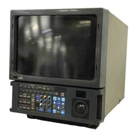
Furuno 1932 MK2 User manual

Back

The paper used in this manual
is elemental chlorine free.
FURUNO Authorized Distributor/DealerFURUNO Authorized Distributor/Dealer
9-52 Ashihara-cho,9-52 Ashihara-cho,
Nishinomi
y
a 662-8580, JAPANNishinomi
y
a 662-8580, JAPAN
Tele
p
hone :Tele
p
hone : 0798-65-21110798-65-2111
Fa
x
Fa
x
0798-65-42000798-65-4200
::
FIRST EDITION :FIRST EDITION : JUN.JUN. 19991999
Printed in JapanPrinted in Japan
A
ll ri
g
hts reserved.
A
ll ri
g
hts reserved.
A2A2 :: NOV.NOV. 07, 200507, 2005
Pub. No.Pub. No. SME-34620-A2SME-34620-A2
*00081001800**00081001800*
*00081001800**00081001800*
(( YAKIYAKI )) MODEL1932/1942 MARK-2MODEL1932/1942 MARK-2 * 0 0 0 8 1 0 0 1 8 0 0 ** 0 0 0 8 1 0 0 1 8 0 0 *
*SME34620A20**SME34620A20*
* S M E 3 4 6 2 0 A 2 0 ** S M E 3 4 6 2 0 A 2 0 *

CONTENTS
Chapter 1. General
1.1 Outline ........................................................................1-1
1.2 Boards & Major Components......................................1-2
1.3 Specifications..............................................................1-3
Chapter 2. Block Description
2.1 Overview.....................................................................2-1
2.2 Display Units...............................................................2-2
2.3 Transceiver Unit..........................................................2-13
2.4 Different Points of Similar PCBs.................................2-15
Chapter 3. Adjustment
3.1 Adjustment of Display Unit.........................................3-2
3.2 Adjustment of Scanner Unit.........................................3-10
Chapter 4. MAINTENACE
4.1 Remarks on Replacement of Major Parts.....................4-1
4.2 Life Expectancy of Expendable Parts...........................4-2
4.3 Menu...........................................................................4-3
Chapter 5. Troubleshooting
5.1 Outline ........................................................................5-1
5.2 Message Indications ....................................................5-1
5.3 Troubleshooting Flow Charts.......................................5-2
Exploded View...............................................................D-1
Mechanical Parts List.................................................M-1
Schematic Diagram.....................................................S-1
Electrical Parts List.....................................................E-1

Chapter 1. General
1-1
1.1 Outline
This manual provides the information necessary for the servicing and adjustment of the radar’s
MODELs 1932MK2 and 1942MK2.
The antenna unit uses a Log IF amplifier.
The table below shows the major specifications of the each model. The same program is installed
on all models, but the menu setting through factory menu is different between the models.
Functions MODEL 1932MK2 MODEL 1942MK2
Maximum range 48 NM 64 NM
Program Number 03591301XX
Tuning Voltage
(displayed at manual tuning) 1 V to 12 V *
Antenna Rotation about 24 or 48 rpm
Output power 4 kW 6 kW
The major parts and P.C. Boards used in the display and scanner units are tabulated on the next
page.
*: 1 to 12 V; M1832, M1932 MK2 and M1942 MK2, 5 to 32 V; M1932, and M1942

1.2 Board & Major Components
1-2
1.2 Boards & Major Components
Board MODEL 1932MK2 MODEL 1942MK2
PROCESSOR Board SPU-9211
POWER SUPPLY Board PTU-9205
FILTER Board FIL-9206
PANEL Board PNL-9212
INTERFACE Board INT-9213
Auto Plotter
(Option: ARP-10) 18P9007
DISPLAY UNIT
(See note.)
CRT Unit QB1069
MODULATOR Board 03P9235A 03P9235
IF AMP Board IF-9214
I/F Board 03P9249
MIC RU-9390
Magnetron E3571 MG5389
Circulator RC4365
SCANNER UNIT
Scanner Motor RM-8025 (24 rpm), RM-8711 (48 rpm)
Note)
The display unit is the same as that of MODEL 1832, 1932 and 1942 in hardware. The software
change is made in the factory menu. See Chapter 2.

1.3 Specifications
1-3
1.3 Specifications
SCANNER UNIT
MODEL 1932MK2 MODEL 1942MK2
Radiator Type Slotted Waveguide Array
Radiator Length 100 cm 120 cm
Horizontal Beamwidth 2.4!1.9!
Vertical Beamwidth 27!22!
Within "20!
of mainlobe –24 dB or less
Sidelobe
Attenuation Outside "20!
of mainlobe –30 dB or less
Polarization Horizontal
Antenna Rotation 24 or 48 rpm nominal
Scanner Housing Stureruct Open Radiator
Standard 1.1 m 1.0 m
Compass
Safe Distance Steering 0.8 m 0.74 m
TRANSCEIVER
MODEL 1932MK2 MODEL 1942MK2
Magnetron E3571 MG5389
Frequency & Modulation 9410 MHz "30 MHz, P0N
Peak Output Power 4 kW nominal 6 kW nominal
0.08 µs, approx 2100 Hz
(Short Ranges: 0.125 nm to 1.5 mm)
0.3 µs, approx 1200 Hz (Middle Ranges: 1.5 nm and 2 nm)
Pulse Length &
Pulse Repetition Rate 0.8 µs, approx 600 Hz (Long Ranges: 3 nm and above)
Modulator FET Switch
Duplexer Circulator with diode limiter
Receiver Front End MIC (Microwave IC)
Tuning Automatic or Manual
Intermediate Frequency 60 MHz
Bandwidth 25 MHz (0.08 µs, 0.3 µs), 3 MHz (0.8 µs)

1.3 Specifications
1-4
DISPLAY UNIT
MODEL 1932MK2 MODEL 1942MK2
Picture Tube PPI (Raster scan, Daylight display)
MODEL 1932MK2: 48 nm
MODEL 1942MK2: 64 nm
Range Scale (nm)
0.125 0.25 0.5 0.75 1 1.5 2 3 4 6 8 12 16 24 36 48 64
Range Ringe Interval 1/16 0.125 0.125 0.25 0.25 0.5 0.5 1 1 2 2 3 4 6 12 12 16
Number of Rings 22434343434444344
Bearing Resolution 2.4!1.9!
Range Discrimination Better than 20 m
Bearing Accuracy "1!
Minimum Range Better than 25 m
Range Ring Accuracy
VRM Accuracy 0.9!or 8 m, whichever is the greater
Input/Output Terminal
NMEA (two input) : NMEA 0183
NMEA (output) : NMEA 0183 ($RATLL, $RARSD, $RATTM: ARP-10
(option) )
GYRO (output) : FURUNO clock-serial (AD format) or NMEA 0183
(HDT, VHW, HDG, HDM)
External Buzzer (output): +12 V source pulse Open Collector
Slave Display (output): TRU-HD, BP, TRU-TRIG, VIDEO
Nav Data
NMEA 0183 Format (••: any talker)
$••APB, $••BWC, $•• BWR, $••DPT, $••DBT, $••GGA, $••GLL,
$••GLC, $••GTD, $••HDG, $••HDM, $••HDT, $••MDA, $••MTW,
$••RMA, $••RMB, $••RMC, $••VTG, $••VHW, $••XTE,
Standard 0.75 m
Compass
safe
Distance Steering 0.6 m

1.3 Specifications
1-5
ENVIRONMENTAL CONDITIONS
ITEM SPECIFICATIONS
Scanner Uint –25 #to +70 #
Ambient
Temperature Display Unit –15 #to +55 #
Humidity Relative humidity 93 % "2 % or less at +40 #"3 #
Vibration IEC 945
POWER SUPPLY & POWER CONSUMPTION
POWER SUPPLY SPECIFICATIONS
DC Ship’s Mains 10.8 V to 41.6 V
MODEL 1932MK2 : 40 W approx
MODEL 1942MK2 : 48 W approx
AC Ship’s Mains 100/110/220/230 VAC, 50/60 Hz, 1$
Rectifier RU-3423 required

Chapter 2. Block Description
2-1
2.1 Overview
The simplified block diagram of the system is illustrated below.
Mag. MIC
Mod. IF
Amp
RF Module
Antenna
Scanner Unit
Processor
Panel Power
CRT
Ship’s mains Nav.
Gyro
Display Unit
HD,BP
Video
Trigger
M1832-SME-8
Figure 2.1 Simplified block diagram of system
TX
The trigger pulse from the PROCESSOR Board is delivered to the MODULATOR Board, fires the
magnetron, and then radar wave is emitted from the radiator.
RX
The 9.4 GHz echo signal received by the antenna is converted to 60 MHz signal by the MIC,
amplified by IF Amp, and fed to thePROCESSOR Board as a video signal. It is digitally processed
and then displayed on the CRT.

2.2 Display Unit
2-2
2.2 Display Unit
Refer to the block diagram on page 2-3.
2.2.1. Power Supply Circuit (PTU-9205)
The constant voltage generator Q1 is in operation even when power switch is off, if ship's mains is
supplied. The power supply circuit is basically consists of a main inverter and a sub inverter. The
main inverter derives the isolated line voltages +12 V/ANT+12 V and -12 V/ANT -12 V from the
main input. The sub inverter derives +5 V and +32 V from +12 V output of the main inverter.
Main inverter
The PWR switch becomes "open" when it is set to on position.
When the PWR switch is pressed, about 9 V is input via PWR line (J1 #13), Q2 is on, and DC+10
V is applied to the PWM.
When power is supplied to the PWM controller, it starts operation and alternately turns on and off
two switching FETs Q3/Q4 connected to the primary widing of T1. The resultant AC voltage
obtained on the secondary windings are rectified and smoothed to +12 V and -12 V, and delivered
to various circuits in the equipment. The voltage taken from the +12 V line is fed back to the PWM
controller through the VR1 to maintain the +12 V output constant.
Sub inverter
U5 and the associated circuit form a PWM switching regulator for +5 V and +32 V. The voltage
taken from +5 V line is fed back to U5 through R37 resistance to maintain the +5 V output
constant.
Protectors
Protection of power supply circuit is achieved by stopping the drive signals to the switching FETs
Q3/4.
Overload on +5 V and + 32 V line is detected by U6. Overload on +12 V (MOTOR + ) line is
detected by U7. When the +5 V and + 32 V line is reduced by a heavy load, U6 or U7 becomes
conductive and consequently disablesthe PWM controller through Q6, Q7 and Q8. Overcorrecton
the main input line is detected by R13, R14 and R15. The voltage drop across Q6, Q7 and Q8
becomes large when the inverter is overload. Overcorrect detector U3 disables PWM inverter U2
when the voltage drop exceeds a certain level.
Overvoltage of mains input is detected by the U1. When the input voltage exceeds 41.6 V, the U1
becomes active and disables PWM controller U2.
Scanner motor power (ANT+12 V/-12 V)
+12 V and -12 V (ANT +12 V/ANT -12 V) are used to drive 24 V scanner motor.
The power to the motor is turned on/off by the relay (K1) on the POWER SUPPLY Board. The
relay control signal from the SPU Board is supplied to Q52 and Q53 on the POWER SUPPLY
Board. Pressing the TX key changes the ANT SW signal state from 5 V to 0 V, and K1 is on to
supply + 12 V.
2.2 Display Unit
2-3
CR36
SHIP’s MAIN
DC10.2
to 41.6V
1
2
2
9
10
-12V
GND
MOTOR(+)
6
J1351 CR1 T1
TP3
L33
PROTECT
L1/C1
L31 J1
VR1
T2
TO INT BOARD
+5V
+32V
+12V
R37
CR37
POWER SUPPLY BOARD (PTU-9205)
Q3
U2
INPUT
OVERCURRENT
PWM ERROR
AMP
Q31/CR33
PWM
U5
LINE
FILTER REVERSE
POLARITY
PROTECTOR
MAINTAIN
PROTECT
J1301
C34 3
K1
Q33
7
8
C31
C32
C54
C38
M1832-SME-09A
FILTER BOARD(FIL-9206)
1
2
3
4
Q4
U3
Q1
+10V
REG.
Q2 U1
INPUT
MONITOR
OVER-
CURRENT
U4
CR31
CR32
TP4
L32
+12V Adj.
4
5
1
11 ANT. SW
9
13
7
DC(+)
PWR
DC(-)
0 V when power is on and about 9 V when power is off, use DC(-) line.
About 9 V even when SW is off, use DC(-) line.
ST-BY:5 V, TX: 0 V
U6
OVER-
CURRENT
(+5V,+32V)
OVER-
CURRENT
U7
10 Vdc supplied at power on
(measured between TP1 and TP2)
TP1
TP2
TP32
TP31
Fuse
Power Cable
03S9332-0
OVERLOAD
Figure 2.2 BLOCK DIAGRAM OF POWER SUPPLY

2-4
CPU
U32
(1640Hz, 4096 pulse)
BEARING
VIDEO
HEADING.P
TRIG
Selecter
EXT TRIG
FILTER
TUNE IND
U26
U24
U22
U27
U25
U23
LEVEL 1
LEVEL 2
LEVEL 3
TRIG GEN,
ECHO SAMP,
INT REJ,
NOISE REJ
U46
03S9060
LEVEL 5
LEVEL 4
FLASH
ROM
U36 U29
RAM GDC
SYSTEM ADDRESS/DATA BUS
10
M1832-SME-10
J104
16
13
14
10,11
2,3
4
J102
R2/C1
U20
U21
C VT(MAX: 5 V, MIN: 1 V)
F VT(MAX: 5 V, MIN: 1 V)
D/A CONV.
CLK
DATA
EEPOT
U14
A/C AUTO
U16
TP3 (VIDEO LEVEL)
GAIN,
A/C SEA
Q17/18
CR12
A/C RAIN ES 2
U16
LEVEL 6
LEVEL 7
VRAM
Echo,
Echo trail
Echo/
Graphic data
overlay,
Priority Brilliance
Selection
D/A
CONV.
U30,31
U45 Q19~26
Q31,32
Timing ADJ.
U45
TRUE
SMPL
TXT
BASE
TRIG
SMPL
TRIG
INT
TRIG
20
EXT TRIG
Echo
Processing
Echo Trail,
ES1)
To RF unit
J104
7
TX TRIG
COORDINATEs
CONV. (R,
) to
(X,Y)
U40
X Y
ADDRESS
SYNC
ES2 ON or OFF
(From U40 #54)
O N: 5 V
OFF: 0 V
A/C AUTO ON or OFF
(From U40 #53) ON: 5 V, OFF: 0 V INPUT
STC CURVE
TP4
D/A CONV. I/F
U42
PLL
U8
BP
(180Hz, 450 PULSE)
VCO(369kHz)
PLL(180Hz)
TP1
TP7
#3
#18
15
#1
PLL
U8
KEY INPUT
#79,80
3,4
NAV DATA
#66
5,6
DATA
SELECTER
U39
#67
NAV1/2 data selection
NAV1
NAV2 Nav data selected
12,13
14,15
#62
GYRO DATA/
NAV DATA
GYRO DATA
SHIFT-CLK
U46
NMEA 0183 HDG/HDT/VHW
G/A
#25 #26
ANALOG
J108
OMNIPAD
#19
#20
#21
#24
TB XA
TB XB
TB YA
TB YB
13
15
14
AC SEA VR
GAIN VR
A/C RAIN VR
J101
Panel
J104
EEPROM I/F
U42
U33
MARK/
CHARA-
CTER
ADDRESS/
MULTIPLEXER VRAM
U43,44
U43:MARK 0/1
U44:CHARACTER,
MASK
GRAPHIC DATA
H/V SYNC
2,5 To CRT
D/A CONV. I/F
DRIVER
U19
ECHO
77.7MHz
U34
CLOCK
GEN.
U45
SAMPLE
CLK
READ CLK
BEARING
DATA
RANGE
DATA
EEPROM
U48
#16,17
#6
#7
STC VS *1
MBS LVEL(For MBS adjustment, setting of 000: 0V, 025: 4V)
#12
#13
U5
#5
#3
#8
J104
CONTRAST VOLTAGE (MAX: approx 5 V, MIN: approx 2 V)
#8
H/V SYNC
To U15 #3
8
PULSE(#1),
UP DOWN(#2),
CS N(#7)
*Functions only
on Tune/video
adj menu.
PULSE(#12),
UP DOWN(#11),
CS N(#10)
J107
SPEED
GYRO
TRUE HD
BP(4096 pulse)
TRUE TRIG
VIDEO
From DATS BUS
From U3,U4
From U32 #21
From U45 #61
From U42 #53
From U16 #10 A9 ARPA VIDEO
A13 SAMPL T
A4 SCAN INT
A11 TRUE HD
A2,
A3 GYRO DATA,CLK
ANALOG ECHO STRETCH
ADDRESS
DECODER
U42
CS ROM
CS RAM
TUNING CONT.
MBS L GAIN
U42 U42
U42
U42
VIDEO
TP8
TP6 (V SYNC)TP5 (H SYNC)
(STC CURVE)
TP2
For ARP-10
*1: Changes STC curve depending on menu setting such as ANT height and STC curve. *2: Short (PL A: 0 V, PL B: 0 V), Middle (PL A: 12 V, PL B: 0 V ), Long(PL A: 12 V, PL B: 12 V)
(Manual Tuning)
MAX: 11.9 V displayed,
13 V measured
MIN: 1.0 V displayed, 2V measured
4V
16.8ms
4V
64 s
64 s
Max Brilliance: 4 Vpp
Min Brilliance: 1 Vpp
13 s
12V
2.5Vpp
4.76 V
4.73 V
4.70 V
4.60 V
4.44 V
4.22 V
3.90 V
#2
4 Vpp
#31
MAX: approx 4 V, MIN: 0V
MAX: 0 V, MIN: approx -9 V
MAX: 0 V, MIN: approx -7 V
0.7 V
approx
7 V 0 V
ST-BY: 0 .7 V, TX: approx 2.5 V
#2: LEFT SIDE(-1 V), RIGHT SIDE(+1 V)
#3: UPPER SIDE(-1 V), LOWER SIDE(+1V)
3 Vpp 3 Vpp
A/C AUTO: OFF A/C AUTO: ON
PL A/PL B *2
J104
TRU HD
DIMMER
ANT SW
EXT BUZZER
J105
J101
11,
12
2
6
J103
17
J109
3
ST-BY: 5 V
TX: 0 V
ANT HIGHT
Low: approx 4.5 V
Mid: approx 3.7 V
High: approx 3 V
#31
#5#3
approx
4.5
Vpp
approx
2.2
Vpp
NAV DATA
GYRO DATA
INPUT
To CRT
θ
U49
A/D CONV.
PHOTO
ISOLATOR
U4
PHOTO
ISOLATOR
U3
U1
U2
PHOTO
ISOLATOR
PHOTO
ISOLATOR
D/ACONV.
COMPARATOR
GEN.
U21
U46
Figure 2.3 BLOCK DIAGRAM OF PROCESSOR PCB SPU-9211

2.2 Display Units
2-5
AUTOMATIC TUNING
There are two types of automatic tuning; peak search and short search.
Peak search: Tuning voltage (TUNING), point A in the figure below, is searched in the tuning
voltage range 0 V to 12 V. Tuning indicator voltage (TUN-ING IND) is maximum
at point A.
Search conditions: After initial tuning adjustment.
Search time: 3 sec approx.
Short search: Maximum tuning indicator voltage A is searched in the tuning voltage range of A
!2.5 V.
Search conditions:
1) After initial tuning adjustment.
2) When tuning method is switched from manual to automatic.
3) When the radar is switched from ST-BY to TX.
4) When a range where pulse length is changed from short to middle and from
middle to long is selected.
Tracking: After short search, tracking takes place.
Tracking voltage: 0 V to 12 V
Tuning indicator
voltage
(TUNING IND)
Tracking
Time
0
Peak search Short search M1832-SME-11
0 V
12 V
Pulselength: LP LP MP SP
Restores previous pulselength
Tuning voltage
(TUNE) A
123
MODEL 1932MK2/1942MK2

2.2 Display Units
2-6
TUNING INDICATOR
After tuning adjustment, peak TUNING IND voltages, ", #and $in the figure on page 2-5 are
stored on to E2PROM.
The automatic and manual tuning point A is also memorized. Using these data, thetuningindicator
extends more than 80 % on ALL TX pulses.
Note that the extension on short pulse is shorter than on longpulse. Theindication becomes shorter
with the magnetron deteriorated.
MANUAL TUNING
The manual tuning voltage changes from 1 to 12 V on M1932MK2/1942MK2 at the steps of about
0.1 V.
Manual Tuning is carried out by using omnipad: pressing "Left" side decreases TUNING CONT
voltage, pressing "Right" side increases.
The TUNING CONT voltage displayed on the screen differs by about 0.1 V from the measured
voltage at J104 #10. Manual Tuning and tuning adjustment are required when automatic tuning is
abnormal (that is, low sensitivity).
J108
2,3 A/D
CONV.
U49
CPU
U32
D/A
CONV.
I/F
U42
D/A
CONV.
U21
From Omnipad
F VT J104
10 TUNING CONT.
(To RF unit)
C VT
#5
#3
#8
#7
#1
U5
#1
#10
M1832-SME-10B
x 6
x 1 SUM
0 to 5V
0 to 2 V
#2: Left side pressing (-1V),
Right side pressing (+1V)
F VT: Fine tuning voltage.
C VT: Course tuning voltage.
TUNING CONT. Operation (from power-on to stand-by)
A square wave is automatically output as a TUNING CONT signal during stand-by just after
power-on. The coarse and fine tuning circuit is normal if the wave is correctly output.
Output voltage depends on the model as follows.
M1832-SME-12
0V
MODEL 1932MK2/1942MK2
0
12 V
5 V F VT
C VT

2.2 Display Units
2-7
Video Adjustment
The video adjustment is carried out through the Tune/video adjustment menu in the installation
setup menu.
The following describes the outline of the adjustment.
"%Main Bang suppression Level (MBS L) is set to 0.
#%EEPOT, U14 is set to minimum. (EEPOT initialization with "L" level of U14 #7)
$%EEPOT gets into step-up mode (U14 #2 is H.) to measure output video level at each step.
The step is changed by pulses applied to U14 #1. The step where the output level is 2.2 V is
memorized.
&%EEPOT gets into step-down mode (U14 #2 is L) to find and stores the step number where the
output level is 2.2 V.
'%Averaging the step numbers found in steps 3 and 4 above, and saving onto depot. The stored
value is not erased when power is turned off.
(%MBS L is reset to the value previously used.
VIDEO
(From IF AMP)
EEPOT
32 step
EEPOT
(VIDEO output ) 2.2 V
UP Down
M1832-SME-12A
➁➂①➃➄
Step: ➅
Heading
Heading data in AD format or NMEA format HEADING DATA (HDT, HDG, HDM, VHW) can
be input from J104(HDG). The radar determineswhether AD format heading data is normal ornot
by checking CLK (J104 #14, #15) data. If CLK data is normal but the DATA line is abnormal, the
heading is continuously shown as 000.0.
When the CLK line is abnormal the heading is continuously shown as ***.*. (Note that the same
indication appears when noise in the CLK line causes deflection of heading data which is higher
than 360.0°.)
The radar can read AD format data at intervals of up to about 100 ms. When the radar is connected
with the equipment whose input interval is 1 sec, heading data is update too slowly, which results
in delayed rotation of the picture when the ship turns.
Automatic switching of NAV data (NMEA 0183)
NAV data from NAV data ports, J104 (#3, #4) and J104 (#5, #6), are alternately selected by the
CPU in the following manner.
Two inputs: Data from J104 (#3, #4) and J104 (#5, #6) are automatically switched every five
seconds.
One input J104 (#3, #4): For three minutes after the power is turned on the data from J104 (#3, #4)
and J104 (#5, #6) is automatically switched every five seconds to determine which port is
inputting NAV data. When J104 (#3, #4) alone is inputting NAV data, data is automatically
switched at J104 (#3, #4) after 25 seconds and after 5 seconds at J104 (#5, #6).

2.2 Display Units
2-8
Turning on/off antenna rotation
The SPU board controls antenna rotation. In normal operation, the antenna rotates during the TX
condition. However, the antenna can be stopped during the TX condition thru the Installationsetup
menu.
J101
10,
11
CPU
U32
TX key
pressed
J103
17
M1832-SME-10C
G/A
U40
ANT SW
TX: 0 V
ST-BY: 5 V
SPU Board INT9213 Board
+12V
Relay
K1
J1
11
1
11
1
ANT SW
J201
J203
17
1
MOTOR(+)
DJ1
To scanner motor
TX: 12 V
ST-BY: 0 V
PTU-9205 Board
Verification of ARP connection
At every power-up, SPU board checks whether ARP-10 is connected or not.
Data line between SPU and ARP boards is used for this check.
If a target cannot be acquired and "ARP" line ismissed in the self test display, the data line must be
checked. When CR1 on the ARP board lights, the ARP board may be defective.

2.2 Display Units
2-9
Block Diagram of ARP PCB
1) ARP-10 dose not require QV echo adjustment at installation, unlike other existing ARPs.
No checkpoint for QV echo is provided. The ARP display can be turned on/off thru the ARP
menu. The ARP data appears even when ship's speed and gyro data are not supplied
2) The ARP board is checked whether it is installed or not at every power-on, using the
communication line between SPU and ARP boards.
When the ARP display is on thru the menu and the ARP board is not fitted, the message " ARP
is not connected" appears.
3) When the target is not acquired, carry out the self-test at TX condition.
TRIGGER/VIDEO/BP/HD must be OK, and FE-DATA 1/DATA 2 must vary depending on the
gain setting. The lower the gain setting, the smaller the FE DATA value. The FE DATA must
not exceed 1000 with the maximum gain setting.
4) The program is stored on the flash ROM, not PROM, so a program writter MT-08 or PC is
required for updating the program.
1TX1H
J3
ARP Board (18P9007)
M1832-SME-09B
TP1,9
CPU CORE
UART
TRANSMIT
UART
RECEIVER
DMA
CHANNEL
TIMER
(10ms)
U13 V821( PD70741GC-25)
TARGET DATA (TTM:CURRENT LOOP)
2TX1C
3
4
RX1H
RX1C
CR1(Blinks 1sec)
I/F for SPU communication
(U14,15,16,23,24)
FLASH ROM
2M bit(U11)
RAM
512K bit(U9,10)
PROGRAM/DATA
(256K bit x 2)
FE
Front End signal
processor(U3)
¥Width
¥Flags
¥Range/azimuth
¥Time
A/D CONV.
A9 VIDEO
TP8
RAM(U4,5)
512K bit Echo data temporary memory
(256K bit x 2)
A17 LOG
A2
A3 GYRO DATA, CLOCK
A13 TRUE TRIG
A11 TRUE HD
TRUE HD
BP(4096/rotation) A4 SCAN INT
TRUE TRIG
GYRO(AD Format,25msec)
LOG(Contact signal): Not used
J107
TP6(Factory use)
TP5
(Factory use)
TP4
TP7
(CLK OUT)
TP2
41.446MHz
NOT USED
NMEA ship’s speed data input
U1
(18S9010)
A7 EXT TXD
(Output from NMEA 1 via SPU)
Figure 2.4 BLOCK DIAGRAM OF ARP PCB 18P9007

2.2 Display Units
2-10
Target acquisition by Auto plotter
Conditions for manual acquisition
1) Within 9 scans, the target must be detected near the cursor position.
2) Target echo must be smaller than land echo (800 m or less in the radial or circumferential
direction) at the front-end processor.
3) Target must be within acquisition area: 0.1 to 16 nm.
4) The number of acquired targets is not as many as 10, including the target manually acquired.
5) No signal error (TRIG, HD, BP, VIDEO, GYRO) shall be detected.
Conditions for automatical acquisition
1) The target must be detected for five consecutive scans within the automatical acquisition area.
2) Target echo must be smaller than land echo (800 m or more in the radial or circumferential
direction) at the front end processor.
3) Target must be within acquisition area: 2.0 to 2.5 nm and 45°each side of heading line.
4) The number of acquired targets is not as many as 10, including the target automatically
acquired.
5) No signal error (TRIG, HD, BP, VIDEO, GYRO) shall be detected.
Automatic tracking
1) A tracking target is judged as a lost target when no return is received for nine consecutive
sweeps. When the system detects a loss of a tracking target, the target symbol becomes a
flashing diamond.
2) A lost target will be reacquired and tracked when acquisition condition again becomes
satisfactory.
3) Automatic tracking is discontinued when the target moves out of the acquisition range (less
than 0.1 nm or greater than 16 nm).
Target discrimination
A target measuring about 800 m or more in the radial or circumferential direction is regarded as a
landmass and not acquired or tracked. Echoes smaller than about 800 m are regarded as true target.

2.2 Display Units
2-11
ARP self-test
[Self test]
Key test: Press each key and
check on-screen indication lights
: 0359139-1xx
: OK
: OK
ARP-10
ROM
RAM
SPEED
COURSE
TRIGGER
VIDEO
BP
HP
MIN-HIT
SCAN-TIME
MAN-ACQ
AUTO-ACQ
FE-DATA1
FE-DATA2
TEST
1859027101xx
NAV 0.0KT
287.6ß
0003
0250
03
05
0217
0023
OK
OK
OK
OK
OK
OK
OK
OK
ARP test items
(test must be made in TX.) Program number and
revision level.
M1832-SME-09C
Hours in use 000026.6 H
Tx houres 000012.7 H
Program No
ROM
RAM
Items Description
ROM U11 checksum
RAM Operation of U9 and U10
SPEED NMEA0183 speed data input
COURSE Bearing data from GYRO
TRIGGER TRU TRIG signal from SPU board
VIDEO VIDEO signal from SPU board
BP Bearing signal (4096 pulses) from SPU board
HP Heading signal from SPU board
MIN-HIT 3 for more
SCAN-TIME HP input interval (250 = 2.5 ms)
MAN-ACQ Number of manually acquired target
AUTO-ACQ Number of automatically acquired target
FE-DATA 1 Number of output echoes from front-end signal processor. If this value is "0" with
maximum gain, the ARP board may be faulty
FE-DATA 2 Number of echoes with a land flag
185902710XX Program number of ARP board
NAV •AD format (GYRO) only: 0.0 kT and gyro reading
•AD format (GYRO) plus NMEA: speed and course in NMEA
•NMEA only: Speed and course in NMEA

2.2 Display Units
2-12
TTM data Sentence format (J1352)
$RATTM, xx, x. x, x. x, a, x. x, x. x, a, x. x, x. x, a, c--c, a, a, a <CR><LF>
M1832-SME-09E
11
14
13
12
10
9
8
7
6
5
4
3
2
1
Hardware: Current loop
Software: NMEA 0183 (Ver 2.0)
TTM: Tracked target message
1. Target number, 00 to 99
2. Target distance from own ship
3 & 4. Bearing from own ship, degrees true (T)
5. Target speed
6 & 7. Target course, degree true/relative (T/R)
8. Distance of closest point of approach (00.00 to 99.99 nm)
9. Time of CPA (00.0 to 99.0 min)
10. Speed/distance units (N: nm)
11. User data (e.g. target data)
12. Target status (see note)
13. Reference target (R)
14. Type of acquisition (A= automatic, M= manual)
NOTE) (1) Target status:
L = lost, tracked target has been lost
Q = query, target in the process of acquisition
T = tracking
E = end, end of tracked (Enforced termination)
(2) x.x: Variable length
This manual suits for next models
1
Table of contents
Other Furuno Plotter manuals

Furuno
Furuno FRS-1000A User manual

Furuno
Furuno GP-3500 Manual

Furuno
Furuno GPS Plotter GP1600 User manual

Furuno
Furuno LP-1000 User manual

Furuno
Furuno RP-180 User manual

Furuno
Furuno GP-1810F Manual

Furuno
Furuno RP-25 User manual

Furuno
Furuno RP-17 User manual

Furuno
Furuno RP-340 User manual

Furuno
Furuno GD-188 User manual

Furuno
Furuno NavNet TZtouch TZTL9BB Manual instruction

Furuno
Furuno GP-280 User manual

Furuno
Furuno GP-1810 User manual

Furuno
Furuno GP-25 User manual

Furuno
Furuno GP-1670 User manual

Furuno
Furuno GP-3500 Manual

Furuno
Furuno GP-3100 Mark-2 User manual

Furuno
Furuno GP-1871F User manual

Furuno
Furuno GP-1850DF User manual

Furuno
Furuno GP-1670F User manual