Furuno GP-280 User manual

COLOR GPS PLOTTER GP-280/380/680
COLOR VIDEO PLOTTER GD-280/380/680

Your Local Agent/DealerYour Local Agent/Dealer
9-52 Ashihara-cho,9-52 Ashihara-cho,
Nishinomi
y
a, Ja
p
anNishinomi
y
a, Ja
p
an
Tele
p
hone :Tele
p
hone : 0798-65-21110798-65-2111
fa
x
fa
x
0798-65-42000798-65-4200
::
F
IRST EDITION :
F
IRST EDITION : SEP.SEP. 19991999
Printed in JapanPrinted in Japan
A
ll ri
g
hts reserved.
A
ll ri
g
hts reserved.
QQ ::
A
UG.
A
UG. 22,200322,2003
PUB.No.PUB.No. OME-43890OME-43890
*00080880801**00080880801*
*00080880801**00080880801*
(( YOSHYOSH )) GD/GP-280/380/680GD/GP-280/380/680
* 0 0 0 8 0 8 8 0 8 0 1 ** 0 0 0 8 0 8 8 0 8 0 1 *
*OME43890Q00**OME43890Q00*
* O M E 4 3 8 9 0 Q 0 0 ** O M E 4 3 8 9 0 Q 0 0 *

i
SAFETY INSTRUCTIONS
WARNING
Immediately turn off the power at the
switchboard if water leaks into the
equipment or something is dropped in
the equipment.
Continued use of the equipment can cause
fire or electrical shock. Contact a FURUNO
agent for service.
Do not disassemble or modify the
equipment.
Fire, electrical shock or serious injury can
result.
Do not place liquid-filled containers on
the top of the equipment.
Fire or electrical shock can result if a liquid
spills into the equipment.
Immediately turn off the power at the
switchboard if the equipment is emitting
smoke or fire.
Continued use of the equipment can cause
fire or electrical shock. Contact a FURUNO
agent for service.
Make sure no rain or water splash leaks
into the equipment.
Fire or electrical shock can result if water
leaks in the equipment.
ELECTRICAL SHOCK HAZARD
Do not open the equipment.
Only qualified personnel
should work inside the
equipment.
WARNING
Keep heater away from equipment.
A heater can melt the equipment's power
cord, which can cause fire or electrical
shock.
Use the proper fuse.
Fuse rating is shown on the equipment.
Use of a wrong fuse can result in equipment
damage.
Do not operate the equipment with wet
hands.
Electrical shock can result.
CAUTION
Do not use the equipment for other than
its intended purpose.
Use of the equipment as a stepping stool,
for example, can result in personal injury
or equipment damage.
No one navigation device should ever be
solely replied upon for the navigation of
a vessel.
Always confirm position against all available
aids to navigation, for safety of vessel and
crew.

ii
CAUTION
A warning label is attached to the equip-
ment. Do not remove the label. If the
label is missing or illegible, contact
a FURUNO agent or dealer.
WARNING
To avoid electrical shock, do not
remove cover. No user-serviceable
parts inside.
Name:WarningLabel(1)
Type:86-003-1011-0
CodeNo.:100-236-230

iii
TABLE OF CONTENTS
INTRODUCTION........................................ v
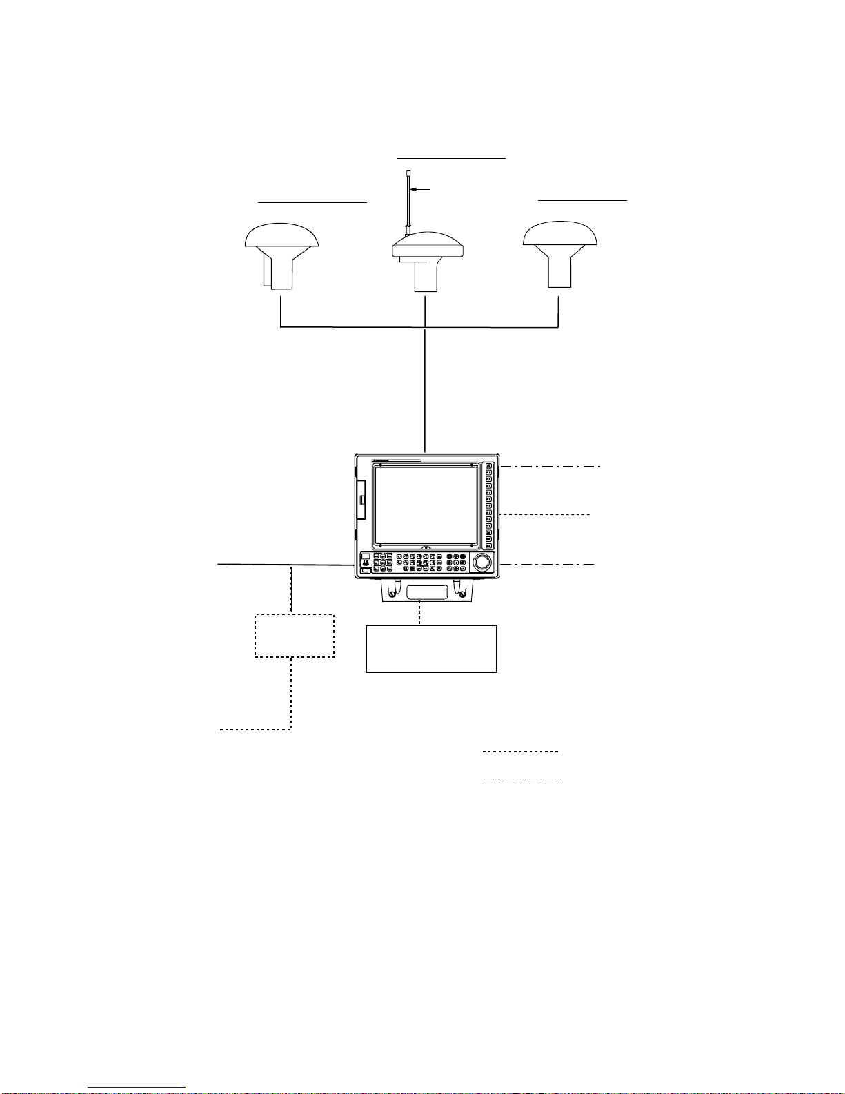
SYSTEM CONFIGURATION................... vii
GP/GD-280 ...................................................vii
GP/GD-380 ..................................................viii
GP/GD-680 ................................................... ix
CONTROLS, MENU OPERATION............ x
Using the Remote Controller........................... x
Control Description........................................ xi
Remote Controller ........................................xiv
Menu Operation............................................ xv
1. OPERATIONAL OVERVIEW
1.1 Getting Started in Operation .................. 1-1
1.2 Function Keys...................................... 1-15
1.3 Indications ........................................... 1-16
2.TRACK
2.1Track Basics.........................................2-1
2.2 Track Color............................................ 2-8
2.3 Setting Track Plotting Interval
(main track) .......................................... 2-15
2.4 Smoothing ........................................... 2-16
2.5 Suspending, Resuming Plotting of
the Track ............................................ 2-18
2.6 Changing Track Color, Line Type ......... 2-20
2.7 Displaying Specific Track ..................... 2-23
2.8 Erasing Track ...................................... 2-26
2.9 Offsetting Chart Data ........................... 2-30
3. MARKS
3.1 Entering Marks ...................................... 3-1
3.2 Erasing Marks........................................ 3-7
3.3 Changing Mark Shape and Color ......... 3-12
3.4 Displaying the Mark Comment List....... 3-13
3.5 Displaying Specific Marks .................... 3-14
3.6 Changing Mark Pattern ........................ 3-17
4. LINES
4.1 Entering Lines........................................ 4-1
4.2 Erasing Lines......................................... 4-6
4.3 Changing Line Shape and Color .......... 4-12
4.4 Displaying Specific Lines ..................... 4-13
4.5 Displaying Line Comments List ............ 4-16
5. WAYPOINTS, ROUTES
5.1 Entering Waypoints................................5-1
5.2 Editing Waypoints ................................ 5-10
5.3 Deleting Waypoints .............................. 5-11
5.4 Setting Course by Waypoints ............... 5-12
5.5 Registering, Changing,
Deleting Routes.................................... 5-13
5.6 Following a Route................................ 5-16
5.7 Calculating Time-to-Go ........................ 5-18
6. ALARMS
6.1 Arrival and Anchor Watch Alarms...........6-2
6.2 XTE and Border Alarms .........................6-5
6.3 Target Proximity Alarm ...........................6-7
6.4 Water Temperature Alarm ......................6-8
6.5 Depth Alarm...........................................6-9
6.6 Current (Tide) Alarm ............................ 6-10
6.7 Ship's Speed Alarm ............................. 6-11
6.8 Wake-up Alarm .................................... 6-12
6.9 Timer Alarm ......................................... 6-12
6.10 Confirming Violated Alarm..................6-13
7. RECORDING & PLAYING BACK DATA
7.1 Data Recording and Memories...............7-1
7.2 Recording Data...................................... 7-4
7.3 Playing Back Data .................................7-7
7.4 Copying Data.........................................7-8
7.5 Confirming Free Space on a Medium .....7-9
7.6 Deleting Files....................................... 7-10
7.7 Offsetting Memory Card Files............... 7-11
7.8 Recording/Replaying Data by
Data Logger ......................................... 7-13
8. TARGET POINT MARK
8.1 Entering a Target Point Mark.................. 8-1
8.2 Erasing a Target Point Mark ...................8-3
9. CALCULATING RANGE & BEARING
10. GPS, DGPS SETTINGS
10.1 GPS Receiver (built-in GPS
receiver only) .................................... 10-1
10.2 DGPS Setting (set with built-in
DGPS receiver)................................. 10-6

iv
11. RADAR OPERATION
11.1 Operation Panel .................................11-1
11.2 Picture Selection................................11-3
11.3 Radar Picture Adjustment...................11-5
11.4 Radar Picture Functions.....................11-8
11.5 Measuring Range and Bearing
to a Target....................................... 11-11
11.6 Cursor Offset....................................11-13
11.7 Target Trails......................................11-15
11.8 Target Alarm.....................................11-18
11.9 Parallel Index Lines..........................11-21
11.10 Clutter Sweep.................................11-23
11.11 Function Key [F9]............................11-24
11.12 A/D Converter Curve ......................11-27
11.13 Set and Drift...................................11-28
11.14 Setting Ship's Speed.......................11-29
11.15 Radar Menus..................................11-30
11.16 Error Messages..............................11-34
12. AUTO PLOTTER
12.1 Auto Plotter Usage Precautions..........12-1
12.2 Introduction to the Auto Plotter ...........12-2
12.3 Activating, Deactivating the
Auto Plotter.........................................12-5
12.4 Acquiring Targets................................12-6
12.5 Terminating Tracking of Targets..........12-8
12.6 Displaying Target Data .......................12-9
12.7 True or Relative Vectors...................12-10
12.8 Vector Time......................................12-10
12.9 Changing Color of Acquisition
Symbol/Vector/ARP Track...............12-11
12.10ARP Past Position Display..............12-12
12.11 Erasing ARP Track.........................12-13
12.12 Changing ARP Track Color.............12-14
12.13 Alarms............................................12-15
12.14 Auto Plotter Menu Description ........12-17
12.15 Track Test ......................................12-18
13. CUSTOMIZING YOUR UNIT
13.1 Plotter DisplayAttributes.....................13-1
13.2 Plotter Display Setup........................13-17
13.3 Graphs.............................................13-21
13.4 Apportioning the Memory..................13-24
13.5 Programming the Function
Keys (F1-F8).....................................13-26
13.6 Other Functions................................13-30
14. MAINTENANCE &
TROUBLESHOOTING
14.1 Maintenance ......................................14-1
14.2 Troubleshooting..................................14-5
14.3 Diagnostic Test...................................14-6
14.4 Clearing Memories...........................14-11
14.5 GPS Monitor Display........................14-12
APPENDIX
1. Geodetic Chart Datum.............................A-1
2. World Time Chart....................................A-2
3. Icons.......................................................A-3
4. Menu Tree...............................................A-4
5. Plotter Display Error Messages .............A-10
SPECIFICATIONS ...............................SP-1
INDEX
Declaration of Conformity

v
INTRODUCTION
FURUNO Electric Company thanks you for considering and purchasing the FURUNO Color GPS
Plotter GP-280/380/680, Color Video Plotter GD-280/380/680. We are confident you will discover
why FURUNO has become synonymous with quality and reliability.
For over 50 years FURUNO Electric Company has enjoyed an enviable reputation for efficient
and dependable marine electronics equipment. This dedication to excellence is furthered by our
extensive global network of agents and dealers.
Your unit is designed and manufactured to meet the rigorous demands of the marine
environment. However, no machine can perform to the utmost of its ability unless properly
operated and maintained. Please carefully read and follow the recommended procedures for
operation and maintenance.
We would appreciate hearing from you, the end-user, about whether we are achieving our
purposes.
Thank you for considering and purchasing FURUNO.
Features
Plotter section
•The GP/GD-280/380/680 mostly shares the same features. The main difference between the
units is the display unit size and equipment incorporated.
GP/GD-280: 12-inch display
GP/GD-380: 15-inch display
GP/GD-680: 21-inch display
Equipment available with the GP-280/380/680
•Standard supply (GPS Plotter)
•DGPS Kit (Built in DGPS beacon receiver)
•FD Kit (Floppy disk drive), Radar Overlay Kit
•DGPS Kit, FD Kit, Radar Overlay Kit
Equipment available with the GD-280/380/680
•Standard supply (Plotter functions only)
•FD Kit (Floppy disk drive), Radar Overlay Kit
•On-screen data include ship's position in latitude and longitude, speed and course, cursor
position, range and bearing to cursor, and range and bearing to waypoint.
•Alarms: Arrival alarm, Anchor Watch alarm, Cross-track Error alarm, Border alarm, Ship's
speed alarm, Wake-up alarm, etc.
•Built-in memory stores 20,000 points total of tracks, marks, lines and comments, 194
waypoints, 10 routes with up to 10 waypoints per route.
•Target points (Max. 10) for marking special locations.

vi
•Comprehensive navigation display of alphanumeric navigation data plus automatic track
plotting.
•Own ship and cursor positions may be shown in latitude and longitude, Loran A, C and
Decca LOPs.
•Two lines of nav data input enables display of two tracks, main and sub, simultaneously.
•Unlimited data storage on memory cards, floppy disks.
•Programmable one-touch function keys (nine keys) provide instant execution of desired
function. 72 (81 with no radar) extension key functions also available.
Radar section (requires optional radar overlay kit)
•Radar and plotter combination display.
•Range 0.125 to 120 nm.
•Target trails feature displays ships' tracks in afterglow.
•Clutter wiper suppresses noise in selected area.
•One-touch setup of radar for optimal detection of buoys, birds, etc.
•Built in auto plotter ARP-10 (GP/GD-280) or ARP-17 (GP/GD-380/680) optionally available.

vii
SYSTEM CONFIGURATION
GP/GD-280
Radar Display Unit
Radar Control Panel
GD-2821
Ship's Mains
12/24/32 VDC Gyrocompass
Speed Log
Display Unit
GP/GD-2800
Rectifier
RU-3423
100/110/115/220/230 VAC
1φ, 50/60 Hz
Whip Antenna
1.2 m GPA-016 (GPS)
GPA-019S (DGPS)
GPA-018S (DGPS)
: Option
: External Equipment
GPS/DGPS Antenna Unit (GP-280 only)
(Requires radar overlay kit.)
Navigation device
(Required for GD-280)

viii
GP/GD-380
Radar Display
Radar Control Panel
GD-2821
Ship's Mains
24/32 VDC Gyrocompass
Speed Log
Display Unit
GP/GD-3800
Rectifier
RU-3423
Whip Antenna
1.2 m GPA-016 (GPS)
GPA-019S (DGPS)
GPA-018S (DGPS)
: Option
: External Equipment
GPS/DGPS Antenna Unit (GP-380 only)
(Requires radar overlay kit.)
100/110/115/220/230 VAC
1φ, 50/60 Hz
Navigation device
(Required for GD-380)

ix
GP/GD-680
Radar Display Unit
Ship's Mains
24/32 VDC Gyrocompass
Speed Log
Display Unit
GP/GD-6800
Rectifier
RU-3423
Whip Antenna
1.2 m GPA-016 (GPS)
GPA-019S (DGPS)
GPA-018S (DGPS)
: Option
: External Equipment
GPS/DGPS Antenna Unit (GP-680 only)
100/110/115/220/230 VAC
1φ, 50/60 Hz
Navigation device
(Required for GD-680)

x
CONTROLS, MENU OPERATION
Using the Remote Controller
The remote controller provides armchair operation of the display unit from up to five meters
away. It is powered by two AA batteries. Install the batteries as below. To operate the GD/GP-
280/380/680 by the remote controller, point the remote controller toward the optical sensor on
the display unit and operate its keys. When the battery voltage is low the distance from which
the display unit can be controlled decreases.
CAUTION
Do not operate the remote controller
with wet hands.
The remote controller may be damaged.
Leave the remote controller in its vinyl
case.
ON
OFF
VIDEO PLOTTER GD-280
How to install
the batteries
Optical
Sensor
Display unit
shown: GP/GD-280

xi
Control Description
GP/GD-280
F1 F2 F3 F4 F5 F6 F7 F8 F9
EVENT
(MOB)
TRACK
ENT START
LINE
ENT SHAPE
MARK
CMNT MENU
DIM
CLR ENT
CNTR
TM/RM HDG
MODE
INFO
DISP BRILL SEL
WPT
ENTRY
SEL
CANCEL
GOTO
0
1+
23
Y
45 6
7
D
98
T
ON
OFF
VIDEO PLOTTER CD-280
COLOR
SEL COLOR
ERASE
ON/OFF
COLOR
SEL
COLOR
SEL
DE-
GAUSS
Registers items on menu.
Opens/closes waypoint entry menu.
Opens/closes comment entry menu.
Opens/closes main menu.
Enter numerical data; select menu; select mark.
Degausses screen.
• Silences buzzer.
• Erases mark, waypoint.
Function Keys
Keyboard Trackball
Optical sensor for
remote controller
Display
POWER Switch
Inscribes mark at ship's
position.
Enlarges/shrinks display.
Returns own ship/cursor
to screen center.
Shift cursor and display;
select items on menu.
Selects heading mode;
CU, NU, HU.
Enables operation
with trackball.
Adjusts display brilliance.
Switches between TM (True Motion)
and RM (Relative Motion).
Adjusts keyboard backlighting.
• Enters mark.
• Selects mark color.
• Selects mark shape.
• Enters lines.
• Selects line color.
• Enters line starting
point.
Sets/cancels
destination.
• Stops/resumes plotting.
• Selects track color.
• Erases track by
color.
Turns cursor on/off; switches between +/-, N/S, E/W.
(Shown on menu as CHG key.)
Displays data; temporarily hides menu, dialog box.

xii
GP/GD-380
Floppy Disk Drive
(Requires FD Kit.)
Chart Card Slot/
Memory Card Slot
GP/GD-380 Display Unit
EVENT
(MOB)
BRILL
DIM
DE-
GAUSS
F9
F8
F7
F6
F5
F4
F3
F2
F1
POWER
ON
OFF
MENU 1
ON/OFF
TRACK
ERASE
COLOR
SEL
TRACK
ENT START
COLOR
SEL
LINE
ENT
SHAPE
COLOR
SEL
MARK GOTO
6
3
8
+
2
7
Y
4
CMNT
WPT
ENTRY
TM/RM
HDG
MODE INFO
DISP
9
CLR
SEL
CANCEL
ENT CNTR
SEL
5
0
GP/GD-380 Keyboard
POWER Switch Trackball
Optical Sensor
D
T

xiii
GP/GD-680
Chart Card Slot/
Memory Card Slot
Floppy Disk Drive
(Requires FD Kit.)
Optical Sensor
GP/GD-680 Display Unit
ON/OFF
COLOR
ERASE
COLOR
SEL
TRACK
ENT
START
COLOR
SEL
LINE
ENT
SHAPE
COLOR
SEL
MARK
MENU
1
GOTO
6
3
8
7
Y
4
CMNT
WPT
ENTRY
RM/TM HDG
MODE
9
CLR
SEL CANCEL
ENT
5
0
+
2
DT
TGT
ALARM
ZOOM
TGT
TRAIL
DIM
DEGAUSS
F9
F8
F7
F6
F5
F4
F3
F2
F1
INFO
DISP
CNTR
SEL
ACQ
CANCEL
EVENT
(MOB)
ARP
DISP MODE
VRM
OFF ON
EBL
OFF ON
POWER
AUDIO BRILL A/C RAIN A/C SEA GAIN
EBL OFFSET(PUSH)
OFF CENTER (PUSH)
A/C AUTO (PUSH)
HL OFF (PUSH)
POWER Switch
Trackball
: Require radar overlay kit. Inoperative
otherwise; buzzer sounds when
operated.
Requires ARP-17.
Buzzer sounds
when not so
equipped.
BRILL Control
AUDIO Control
GP/GD-680 Keyboard

xiv
Remote Controller
The remote controller provides armchair control of the display unit from a distance of up to 4 m.
The remote controller keys operate exactly the same as keys on the display unit.
Note 1: Power on/off, F3-F9, degauss, panel illumination and brilliance are conducted from the
display unit.
Note 2: Replace the batteries when the distance from which the display can be controlled
decreases.
EVENT
(MOB)
INFO
DISP
MENU
TD
CLR ENT
CNTR
ZOOM IN/OUT
SEL WPT SEL CANCEL
GOTO
HDG
MODE ON/OFF COLOR ERASE
TRACK
ENT COLOR START
TM/RM
LINE
ENT COLOR SHAPE
MARK
CMNT
Operates same as F1 and
F2 on the display unit.
However, they cannot be
set independently from the
display unit.

xv
Menu Operation
Most functions are carried out through the menu. This section provides information necessary
for menu operation.
1. Press the [MENU] key to display the main menu.
2. Press appropriate numeric key to display the menu desired. For example, press the [1] key
to select the Plotter Display menu.
Main Menu
0 Plotter Display
1 Track
2 Mark/Line
3 Waypoint/Route
4 Alarm
5 File
6 Target Point
7 Calculate Rng/Brg
8 System Setting
9 Initial Setting
0~9 : Next Page
Menu : Close Menu
Plotter Display
1 Plotter Display
2 Plotter & Graph Disp.
3 Nav Data Display
4 GPS Data Display
5
6
7
8
9
0
______________________
1~4 : Setting
Menu : Esc

xvi
Menu conventions
•Return to main menu: Press the [MENU] key several times.
•Return to previous screen: Press the [MENU] key once.
•Close menu: Press the [MENU] key several times.
•CLR key: Clears entire line of numeric data.
•INFO DISP key: Temporarily hides menu, dialog box. Menu, dialog box reappear after ten
seconds.

1-1
1. OPERATIONAL OVERVIEW
The basic function of a video plotter is to record and plot ship's track, using position data fed from
a navigation device which is built in the display unit or is installed separately.
Once the equipment is properly installed, you need do no more than turn on the power to plot
ship's track. Of course, your equipment does much more than just plot ship's track, and it is our
intention to guide you along in the use of your equipment with instructions that start at a basic
level and proceed forward in a logical manner.
In this chapter you will learn the most basic functions of your equipment, from turning on the
power to how to read the navigation data display.
1.1 Getting Started in Operation
This paragraph provides a quick introduction to some of the most frequently used functions.
All controls respond immediately to the operator's command and a correct key input is
accompanied by a beep. Incorrect operation will emit several beeps.
1.1.1 Inserting a chart card
1. GP/GD-280: Open the keyboard.
GP/GD-380: Open the card slot door at the left side of the display unit.
GP/GD-680: Open the chart slot cover below the keyboard.
2. Insert appropriate chart card in the card slot. Your equipment has two card slots, and either
may be used.
POWER switch
Keyboard
EJECT Button
Insert with grooves
facing upward.
Display unit GP/GD-280
3. Close the keyboard, card slot door or card slot cover as appropriate. Leave the chart card in
the slot while the equipment is turned on. This will allow redrawing of the chart when the
chart is shifted, etc.

1-2
1.1.2 Turning the power on/off
Press the [POWER] switch to turn the power on. The picture changes in the sequence shown in
the figure below.
For equipment using the built-in GPS navigator, the own ship marker (•) immediately starts
blinking (0.5-second intervals) as soon as the power is turned on. This blinking means GPS
position is not yet accurate. The first time the power is applied it takes about 90 seconds to find
position. This is because the Almanac, which contains information about all GPS satellites, is not
stored in the navigator. Once the Almanac is stored, it takes approx. 12 seconds to find position.
When position is found the own ship marker blinks slowly (one-second intervals).
For external navigation device, the own ship mark blinks in one-second intervals when position is
accurate.
CAUTION
Data displayed by this unit
is intended as reference.
Position should be
confirmed against nautical
charts.
FURUNO ELECTRIC CO., LTD
(1)
(2)
(3)
MEMORY TEST
Diagnosis Test
(Displayed momentarily)
PLOTTER DISPLAY
Position in lat./long. +cursor
Own ship marker
(blinking)
STARTUP SELFTEST
ROM OK
DRAM OK
SRAM OK
VRAM OK
BATTERY TEST
INT. BATTERY OK
PROGRAM NUMBER
PLOTTER 14506880**
Press any key.
Displayed about 30
seconds. Press any
key except [DIM] key
and [HL OFF] control
to show the
plotter display.
**: Program Version
No.
If the diagnosis finds fault, the display freezes. To restore normal operation, try to press any key.
To turn off the power, press the [POWER] switch again.
This manual suits for next models
5
Table of contents
Other Furuno Plotter manuals

Furuno
Furuno GP-3100 Mark-2 User manual

Furuno
Furuno GP-1670 User manual

Furuno
Furuno LP-1000 User manual

Furuno
Furuno GP-1871F User manual

Furuno
Furuno GPS Plotter GP1600 User manual

Furuno
Furuno GP-3500 User manual

Furuno
Furuno GP-1810 User manual

Furuno
Furuno GP-1670F User manual

Furuno
Furuno 1932 MK2 User manual

Furuno
Furuno GP-1850DF User manual

Furuno
Furuno Auto Plotter ARP15 User manual

Furuno
Furuno GP-3500 Manual

Furuno
Furuno RP-250 User manual

Furuno
Furuno RP-17 User manual

Furuno
Furuno GP-3500 Manual

Furuno
Furuno RP-180 User manual

Furuno
Furuno FRS-1000A User manual

Furuno
Furuno Auto Plotter ARP15 User manual

Furuno
Furuno RP-25 User manual

Furuno
Furuno GD-188 User manual