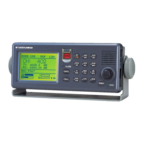
Furuno FM-4721 User manual

MARINE VHF
RADIOTELEPHONE
FM-4721
OPERATOR'S MANUAL
www.furuno.com
MODEL

i
IMPORTANT NOTICES
General
• This manual has been authored with simplified grammar, to meet the needs of international us-
ers.
• The operator of this equipment must read and follow the descriptions in this manual. Wrong op-
eration or maintenance can cancel the warranty or cause injury.
• Do not copy any part of this manual without written permission from FURUNO.
• If this manual is lost or worn, contact your dealer about replacement.
• The contents of this manual and equipment specifications can change without notice.
• The example screens (or illustrations) shown in this manual can be different from the screens
you see on your display. The screens you see depend on your system configuration and equip-
ment settings.
• Save this manual for future reference.
• Any modification of the equipment (including software) by persons not authorized by FURUNO
will cancel the warranty.
• All brand and product names are trademarks, registered trademarks or service marks of their
respective holders.
How to discard this product
Discard this product according to local regulations for the disposal of industrial waste. For disposal
in the USA, see the homepage of the Electronics Industries Alliance (http://www.eiae.org/) for the
correct method of disposal.
How to discard a used battery
Some FURUNO products have a battery(ies). To see if your product has a battery, see the chapter
on Maintenance. Follow the instructions below if a battery is used. Tape the + and - terminals of
battery before disposal to prevent fire, heat generation caused by short circuit.
In the European Union
The crossed-out trash can symbol indicates that all types of batteries
must not be discarded in standard trash, or at a trash site. Take the
used batteries to a battery collection site according to your national
legislation and the Batteries Directive 2006/66/EU.
In the USA
The Mobius loop symbol (three chasing arrows) indicates that Ni-Cd
and lead-acid rechargeable batteries must be recycled. Take the
used batteries to a battery collection site according to local laws.
In the other countries
There are no international standards for the battery recycle symbol. The number of symbols can
increase when the other countries make their own recycle symbols in the future.
Cd
Ni-Cd Pb

ii
SAFETY INSTRUCTIONS
WARNING
WARNING
Do not open the equipment.
The equipment uses high voltage that
can cause electrical shock. Refer any
repair work to a qualified technician.
If water leaks into the equipment or
something is dropped into the equip-
ment, immediately turn off the power
at the switchboard.
Fire or electrical shock can result.
If the equipment is giving off smoke
or fire, immediately turn off the power
at the switchboard.
Fire or electrical shock can result.
If you feel the equipment is acting
abnormally or giving off strange
noises, immediately turn off the
power at the switchboard and contact
a FURUNO service technician.
Mandatory Action
Prohibitive Action
WARNING
CAUTION
Warning, Caution
The operator and installer of this equipment must read the safety instructions before attempting to install
or operate the equipment.
Indicates a potentially hazardous situation which, if not avoided,
could result in death or serious injury.
Indicates a potentially hazardous situation which, if not avoided,
could result in minor or moderate injury.
WARNING
WARNING
Do not disassemble or modify the
equipment.
Fire, electrical shock or serious injury
can result.
Make sure no rain or water splash
leaks into the equipment.
Fire or electrical shock can result if
water leaks into the equipment.
Do not place liquid-filled containers
on or near the equipment.
Fire or electrical shock can result if a
liquid spills into the equipment.
Do not operate the equipment with
wet hands.
Electrical shock can result.
Use the proper fuse.
Use of the wrong fuse can cause fire or
electrical shock.
CAUTIO
CAUTION
Do not touch any part of the antenna
when the equipment is transmitting.
Electrical shock can result.

SAFETY INSTRUCTIONS
iii
WARNING
Do not open the equipment unless
totally familiar with electrical circuits.
The equipment uses high voltage that
can cause electrical shock.
Turn off the power at the mains
switchboard before beginning the
installation. Post a warning sign near
the switchboard to indicate that
power should not be applied while the
equipment is being installed.
Electrical shock, serious injury or fire can
result if the power is not turned off or is
applied while the equipment is being
installed.
RADIO FREQUENCY RADIATION
HAZARD
Distances at which RF radiation level of
100, 10 and 5.05 W/m2are shown
below.
100 W/m2: Not applicable
10 W/m2: Not applicable
5.05 W/m2: 1.0 m
CAUTIO
CAUTION
Confirm that the power supply voltage
is compatible with the voltage rating
of the equipment.
Connection to the wrong power supply
can cause fire or damage the equipment.
Follow the compass safe distances
shown in the table below to prevent
interference to a magnetic compass.
Steering
compass
Standard
compass
1.70 m
Transceiver Unit
FM-4721 1.10 m
0.70 m
Handset
HS-4721 0.45 m

iv
TABLE OF CONTENTS
FOREWORD ..................................................................................................................vii
SYSTEM CONFIGURATION ........................................................................................viii
1. GETTING STARTED..............................................................................................1-1
1.1 Emergency Call (CH16) ............................................................................................. 1-1
1.2 How to Call Another Vessel (CH16 or CH9) .............................................................. 1-1
1.3 How to Make Telephone Calls ................................................................................... 1-2
1.4 Channels 13 and 67 (USA channel group only)......................................................... 1-2
2. OPERATION ..........................................................................................................2-1
2.1 Controls...................................................................................................................... 2-1
2.1.1 Transceiver Unit............................................................................................. 2-1
2.1.2 Handset HS-4721........................................................................................... 2-3
2.2 Reception ................................................................................................................... 2-5
2.3 Transmission.............................................................................................................. 2-5
2.4 Transmit Timeout Timer (TOT) .................................................................................. 2-6
2.5 Simplex/Duplex Channel Use .................................................................................... 2-6
2.6 International, Canada, and USA Mode ...................................................................... 2-6
2.7 Backlight Adjustment.................................................................................................. 2-6
2.8 NOAA Weather Channels .......................................................................................... 2-7
2.8.1 NOAA weather alert ....................................................................................... 2-7
2.8.2 NOAA weather alert test ................................................................................ 2-7
2.9 Dual Watch (To CH16)............................................................................................... 2-8
2.10 Scanning ....................................................................................................................2-8
2.10.1 How to select the scan type ........................................................................... 2-8
2.10.2 How to program the scan memory................................................................. 2-9
2.10.3 Memory scanning (M-SCAN) ......................................................................... 2-9
2.10.4 Priority scanning (P-SCAN).......................................................................... 2-10
2.11 How to Preset Channels (0-7): Instant Access ........................................................ 2-10
2.11.1 How to preset channels................................................................................ 2-10
2.11.2 How to activate preset channels .................................................................. 2-11
2.11.3 How to delete preset channels..................................................................... 2-11
2.12 PA HAIL, FOG HORN Operation ............................................................................. 2-11
2.12.1 PA HAIL mode ............................................................................................. 2-11
2.12.2 FOG HORN mode........................................................................................ 2-12
2.13 Intercom Operation .................................................................................................. 2-13
2.13.1 Communication ............................................................................................ 2-13
2.13.2 How to call on the Intercom.......................................................................... 2-14
2.14 Bluetooth Operation (option) .................................................................................... 2-14
2.14.1 Pairing .......................................................................................................... 2-14
2.14.2 Operation ..................................................................................................... 2-15
2.14.3 VOX feature ................................................................................................. 2-15
2.14.4 Battery saver ................................................................................................ 2-16
2.15 Voice Scrambler (option).......................................................................................... 2-16
3. DIGITAL SELECTIVE CALLING ...........................................................................3-1
3.1 General ......................................................................................................................3-1
3.2 Maritime Mobile Service Identity (MMSI) ................................................................... 3-1
3.2.1 What is an MMSI?.......................................................................................... 3-1
3.2.2 How to enter your MMSI number ................................................................... 3-1
3.3 DSC Distress Alert ..................................................................................................... 3-2
3.3.1 How to transmit a DSC Distress Alert ............................................................ 3-2

TABLE OF CONTENTS
v
3.3.2 How to receive a DSC Distress Alert..............................................................3-5
3.4 All Ships Call ..............................................................................................................3-6
3.4.1 How to transmit an All Ships call....................................................................3-6
3.4.2 How to receive an All Ships call .....................................................................3-7
3.5 Individual Call .............................................................................................................3-7
3.5.1 How to register DSC stations to the Individual Directory................................3-7
3.5.2 How to select the Individual call reply method ...............................................3-8
3.5.3 How to select the Individual call acknowledge method ..................................3-9
3.5.4 Individual/Group call ringer.............................................................................3-9
3.5.5 How to transmit an Individual call.................................................................3-10
3.5.6 How to receive an Individual call..................................................................3-11
3.6 DSC Log...................................................................................................................3-13
3.6.1 Transmitted call log ......................................................................................3-13
3.6.2 Distress log...................................................................................................3-13
3.6.3 Other call log ................................................................................................3-13
3.6.4 How to delete calls from a log ......................................................................3-14
3.7 Group Call ................................................................................................................3-14
3.7.1 How to register DSC stations to the Group Directory...................................3-14
3.7.2 How to transmit a Group call........................................................................3-16
3.7.3 How to receive a Group call .........................................................................3-17
3.8 Position Request Call ...............................................................................................3-18
3.8.1 How to set up a position request reply .........................................................3-18
3.8.2 How to set up the position request ringer.....................................................3-18
3.8.3 How to transmit a Position Request call to another vessel ..........................3-19
3.8.4 When you receive a Position Request call...................................................3-20
3.9 Position Report Call..................................................................................................3-20
3.9.1 How to enable, disable the position report ringer.........................................3-20
3.9.2 How to transmit a Position Report call .........................................................3-21
3.9.3 When you receive a Position Report call......................................................3-22
3.10 Auto DSC Polling......................................................................................................3-23
3.10.1 Selecting stations to be automatically polled (tracked) ................................3-23
3.10.2 Enable/Disable auto DSC polling .................................................................3-24
3.11 Auto CH Switch Time ...............................................................................................3-24
3.12 DSC Test..................................................................................................................3-25
3.12.1 How to make a DSC test call with MMSI in the Individual Directory.............3-25
3.12.2 How to make a DSC test call by manually entering MMSI...........................3-26
4. GENERAL SETUP.................................................................................................4-1
4.1 Display Contrast .........................................................................................................4-1
4.2 Time Offset.................................................................................................................4-1
4.3 Time Area...................................................................................................................4-2
4.4 Time Notation .............................................................................................................4-2
4.5 Units of Measurement ................................................................................................4-2
4.6 COG Display Format ..................................................................................................4-3
4.7 Manual Input of the Position (Lat/Lon)........................................................................4-3
4.8 Key Beep....................................................................................................................4-4
4.9 Treble and Bass Audio Tone Control .........................................................................4-4
4.10 Fog Alert Tone Frequency..........................................................................................4-4
4.11 How to Name the Radio or Handset...........................................................................4-5
4.12 Soft Keys ....................................................................................................................4-6
4.12.1 Transceiver unit..............................................................................................4-6
4.12.2 Handset HS-4721...........................................................................................4-7
4.13 Calendar Setup...........................................................................................................4-7
4.14 How to Set the Timeouts ............................................................................................4-9
TABLE OF CONTENTS
v
. ANNEL UN T N SETUP.............................................................................. -1
5.1 CH Group...................................................................................................................5-1
5.2 Scan Memory.............................................................................................................5-1
5.3 Scan Type..................................................................................................................5-2
5.4 Scan Resume.............................................................................................................5-2
5.5 Priority CH..................................................................................................................5-2
5.6 Weather Alert Setup...................................................................................................5-3
5.7 Channel Naming ........................................................................................................5-4
. AT S SETUP........................................................................................................... -1
6.1 ATIS Code Programming...........................................................................................6-1
6.2 ATIS Channel Group..................................................................................................6-2
. A NTENAN E TR U LES T NG............................................................... -1
7.1 General Maintenance.................................................................................................7-1
7.2 Troubleshooting Chart................................................................................................7-2
7.3 How to Replace the Fuse...........................................................................................7-3
7.4 How to Clear the Memory ..........................................................................................7-3
7.5 How to Reset the Microprocessor..............................................................................7-3
7.6 Daily Test ...................................................................................................................7-4
. NSTALLAT N ..................................................................................................... -1
8.1 Transceiver Unit.........................................................................................................8-1
8.1.1 Desktop or overhead mount...........................................................................8-1
8.1.2 Flush mount (option) ......................................................................................8-2
8.2 Antenna......................................................................................................................8-2
8.3 Coa ial Cable.............................................................................................................8-3
8.4 Electrical Connections................................................................................................8-3
8.5 Accessory Cable ........................................................................................................8-5
8.6 Handset HS-4721.......................................................................................................8-6
8.6.1 How to use an e ternal speaker.....................................................................8-8
8.7 How to Set up the Equipment from the Menu ............................................................8-8
8.7.1 How to set time offset to show local time.......................................................8-8
8.7.2 How to show local time or UTC time..............................................................8-9
8.7.3 How to set the time notation...........................................................................8-9
8.7.4 How to select GPS COG format.....................................................................8-9
8.8 Optional Equipment..................................................................................................8-10
8.8.1 Bluetooth Adapter Unit BU-1........................................................................8-10
8.8.2 oice Scrambler F P-42..............................................................................8-11
APPEN 1 ANNEL ASS GN ENTS ENU TREE ........................................AP-1
SPE AT NS .....................................................................................................SP-1
N E .......................................................................................................................... N-1

vii
FOREWORD
A Word to the Owner of the FM-4721
FURUNO Electric Company thanks you for purchasing the FM-4721 Marine VHF Radiotelephone.
We are confident you will discover why the FURUNO name has become synonymous with quality
and reliability.
For over 60 years FURUNO Electric Company has enjoyed an enviable reputation for quality and
reliability throughout the world. This dedication to excellence is furthered by our extensive global
network of agents and dealers.
Your equipment is designed and constructed to meet the rigorous demands of the marine envi-
ronment. However, no machine can perform its intended function unless properly installed and
maintained. Please carefully read and follow the operation, installation and maintenance proce-
dures set forth in this manual.
We would appreciate feedback from you, the end-user, about whether we are achieving our pur-
poses.
Thank you for considering and purchasing FURUNO.
Features
The FURUNO FM-4721 is a Marine VHF Radiotelephone designed for use in the frequency range
of 156.025 to 163.275 MHz. The FM-4721 can be powered with 10.8 to 15.6 VDC power and has
a switchable RF output power of 1 Watt or 25 Watts.
The FM-4721 operates on all currently allocated marine channels. Channels are switchable for
use with USA, International, or Canadian regulations. Emergency CH16 can be immediately se-
lected by pressing the 16/9 key. NOAA weather channels (where available) can also be accessed
immediately by pressing the CLR/WX key.
The FM-4721 incorporates DSC (Digital Selective Calling) Class D facilities that comply with ITU-
R M.493-12 (DSC Class D). Class D operation provides continuous watch on DSC CH70 even if
the radio is receiving a call.
The main features are
• Class D DSC (Digital Selective Calling) with Distress, Individual and All Ship calls
• Navigation information (LAT/LON, SOG, COG) shown on the display*
• Navigate to a DSC Distress Position*
• Automatic DSC Position Poll request to up to four separate vessels
• Menu system with user-programmable soft keys
• Dedicated channel 70 receiver for continuous DSC watch
• Submersible IPX-7 rating (1 meter for 30 minutes)
• 30 Watt PA/Loudhailer (option) with pre-programmed fog signals and listenback facility
• ClearVoice noise-cancelling microphone with channel selector and 16/9 key
• Handset HS-4721 can operate as a remote station
• Intercom facility between Handset and Radio
• Optional Bluetooth Adapter Unit enables communication with bluetooth devices
• Optional Voice Scrambler provides secure communications with other so equipped FM-4721
*: Requires external GPS navigator.

viii
SYSTEM CONFIGURATION
Voice Scrambler FVP-42
(inside transceiver)
GPS Navigator
External Speaker
Handheld MIC
Handset HS-4721
Loudhailer /PA Horn
Handset HS-4721
TRANSCEIVER UNIT
FM-4721
ANTENNA UNIT
Optional, local supply
equipment indicated
with dashed lines.
10.8 - 15.6 VDC
MEM
Bluetooth Adapter Unit BU-1
(inside transceiver)
Bluetooth Headset BH-2A

1-1
1. GETTING STARTED
1.1 Emergency Call (CH16)
CH16 is known as the Hail and Distress Channel. An emergency may be defined as
a threat to life or property. In such instances, be sure the transceiver is on and set to
CH16. Then use the following procedure:
1. Press the microphone’s push-to-talk (PTT) switch and say "Mayday, Mayday,
Mayday. This is XXXXX, XXXXX, XXXXX" (your vessel's name).
2. Then repeat once: "Mayday, XXXXX" (your vessel's name).
3. Report your position in latitude/longitude, or give a true or magnetic bearing (state
which) to a well-known landmark such as a navigation aid or geographic feature
such as an island or harbor entry.
4. Explain the nature of your distress (sinking, collision, aground, fire, piracy, life-
threatening injury, etc.).
5. State the kind of assistance you desire (pumps, medical aid, etc.).
6. Report the number of persons aboard and condition of any injured.
7. Estimate the present seaworthiness and condition of your vessel.
8. Give your vessel's description: length, design (power or sail), color and other dis-
tinguishing marks. The total transmission should not exceed one minute.
9. End the message by saying "OVER". Release the microphone switch and listen.
10. If there is no answer, repeat the above procedure. If there is still no response, try
another channel.
Note: The FM-4721 has DSC Distress calling, which can send a distress call digitally
to all ships with compatible DSC radios. Refer to chapter 3 “DIGITAL SELECTIVE
CALLING".
1.2 How to Call Another Vessel (CH16 or CH9)
CH16 (or CH9, depending on area) should be used as the calling channel for initial
contact with another vessel. However, its primary purpose is for emergency commu-
nications and should be monitored at all times when not using other channels.
It is monitored by Coast Guard stations in all countries and other vessels.
The use of CH16 should be limited to making initial contact only. Calling should not
exceed one minute, but may be repeated at two-minute intervals.
Prior to making contact with another vessel, refer to the channel charts in the Appen-
dix and select an appropriate channel (working channel) for use after initial contact.
Monitor the proposed channel to ensure you won’t be interrupting other traffic and then
go back to CH16 to make your initial call.
When channel 16 is clear, state the name of the vessel you wish to call and then "this
is" followed by the name of your vessel and your vessel callsign. When the other ves-
sel returns your call, immediately request another channel by saying "go to", the num-

1. GETTING STARTED
1-2
ber of the other channel, and "over". Then switch to the new channel. When the new
channel is not busy, call the vessel.
After a transmission, say "over", and release the PTT (Push-To-Talk) switch on the
microphone. When all communication with the vessel is completed, end the last trans-
mission by stating your callsign and the word "out". Note that it is not necessary to
state your callsign with each transmission, only at the beginning and end of the con-
tact.
Remember to return to CH16 when not using another channel. Some radios automat-
ically monitor CH16 even when set to other channels or when scanning.
1.3 How to Make Telephone Calls
To make a radiotelephone call, use a channel designated for this purpose. The fastest
way to learn which channels are used for radiotelephone traffic is to ask at a local ma-
rina. Channels available for such traffic are designated Public Correspondence
channels on the channel charts in the Appendix. Some examples for USA use are
Channels 24, 25, 26, 27, 28, 84, 85, 86, and 87. Call the marine operator and identify
yourself by your vessel's name. The marine operator then asks you how you want to
pay for the call (telephone credit card, collect, etc.) and then link your radio transmis-
sion to the telephone lines.
The marine telephone company managing the VHF channels you are using may
charge a link-up fee in addition to the cost of the call.
1.4 Channels 13 and 67 (USA channel group only)
Channel 13 is used at docks and bridges and by vessels maneuvering in port. Mes-
sages on this channel must concern navigation only, such as meeting and passing in
restricted waters.
Channel 67 is used for navigational traffic between vessels.
By regulation, power is normally limited to 1 Watt on these channels. Your radio is pro-
grammed to automatically reduce power to this limit on these channels. However, in
emergency situations it may be necessary to temporarily use a higher power. See
page 2-1 (H/L key) for how to temporarily override the low-power limit on these two
channels.

2-1
2. OPERATION
2.1 Controls
This section describes the controls of the Transceiver Unit (including the optional mi-
crophone) and the Handset HS-4721.
2.1.1 Transceiver Unit
No. Control Description
1VOL
(Volume Control
Knob)
• Adjust the audio volume level. Turn this knob clockwise to increase
the audio volume level.
• Control the listenback volume in the PA or Fog mode.
Note: Turn off the set with minimum volume. When you turn on the set,
adjust the volume to a comfortable level. This allows you to hear distress
calls and raw voice clearly.
2SQL
(Squelch Control)
Adjust this control clockwise to set the point at which random noise on
the channel does not activate the audio circuits but a received signal
does. This point is called the squelch threshold. Further adjustment of
the squelch control may degrade reception of wanted transmissions.
3 Soft keys The three soft keys functions can be customized on the Setup Menu.
See section 4.12 "Soft Keys". When one of the soft keys is pressed
briefly, all the functions of the soft keys appear above their associated
keys.
416/9 • Momentary press: Recall CH16 from any channel location.
• Long press: Recall CH9. (CH9 is used in some parts of the world as
an alternative calling channel to CH16.)
Press the key again to return to the previously selected working chan-
nel.
5H/L Toggle between 25 W (High) and 1 W (Low) power. When the TX output
power is set to "Low" while the transceiver is on channel 13 or 67, the
output power is temporarily switched from "Low" to "High" power until
the PTT switch is released. The H/L key does not function on transmit
inhibited and low power only channels.
6CALL/MENU • Momentary press: Open the [DSC Menu].
• Long press: Open the [Setup Menu].
MEM
12345 6 7 8 9
10
11

2. OPERATION
-
7 Select channels and select menu items. The Sand Tkeys on the
microphone can also be used to select channels and menu items.
In the PA or Fog mode, change the output volume of the connected
horn speaker.
8(POWER) Power the transceiver on and off. To turn the transceiver on, press and
hold this key until the LCD turns on. To turn it off, press and hold this key
until the LCD turns off. When the power is turned on, the transceiver is
set to the last-selected channel.
9 MIC connector Connector for the supplied noise-canceling speaker microphone.
10 1When in the radio mode, this key directly inputs the digit 1 in a channel
number.
ER Directly input the digit 2 in a channel number.
UN →E Memori e the selected channel into the
transceiver scan memory for scanning. Repeat the same procedure
(UN →E) to delete the channel from the scan memory. See
section 2.10 Scanning for details.
SAN R Directly input the digit 3 in a channel number.
UN key→SANkey Start and stop scanning on programmed
channels. This function depends on scanning type setting. See
section 2.10 Scanning for details.
4R Directly input the digit 4 in a channel number.
UN key→4key Access the LCD Dimmer menu. See
section 2.7 Backlight Ad ustment for details.
R Directly input the digit 5 in a channel number.
UN key→key Activate the intercom mode between the radio
and the Handset. See section 2.13 Intercom Operation for details.
R Directly input the digit 6 in a channel number.
UN key→key Scan for voice communications on the priority
channel and another selected channel until a signal is received on ei-
ther channel (Dual Watch). See section 2.9 Dual Watch (To CH16)
for details.
SR R Directly input the digit 7 in a channel number.
UN key→SRkey Operate the oice Scrambler function
when the optional F P-42 oice Scrambler Unit is installed. See
section 2.15 oice Scrambler (option) for details.
PA R Directly input the digit 8 in a channel number.
UN key→PA key Operate the 30 Watt PA function. See
section 2.12 PA HAIL, FOG HORN Operation for details.
GR Directly input the digit 9 in a channel number.
UN key→Gkey Operate the Fog Horn function. See
section 2.12 PA HAIL, FOG HORN Operation for details.
In the radio mode, directly input the digit 0 in a channel number.
LR Cancel the menu selection and/or key input.
Press and hold the key to recall the previously selected NOAA weath-
er channel from any channel. Press and hold the key again to revert
to the previously selected working channel.
ENT Confirm the menu selection and/or key input.
UN Activate the Alternate key function.
11 STRESS Send a DSC Distress Alert. See section 3.3.1 How to transmit a DSC
Distress Alert .
N.

2. OPERATION
2-3
2.1.2 Handset HS-4721
The HS-4721 Handset remotely operates all VHF, DSC, setup menus, and PA/Fog
modes. The HS-4721's operation is same as FM-4721 except the receiver audio vol-
ume setting and squelch level setting. The HS-4721 is supplied with 7 m of routing ca-
ble and can be extended up to 21 m using three 7 m extension cables model CT-100.
TheIntercomfeaturecan beusedbetweentheHS-4721and theFM-4721.Inaddition,
speaker wires are supplied at the panel mount of the routing cable to connect an ex-
ternal speaker. This can be useful when it is difficult to hear voice over the handset,
because of noisy environment.
No. Control Description
12 PTT switch
(Push-To-Talk
Switch)
Radio mode, PTT switch pressed: The transmitter is enabled for voice
communications with another vessel.PA mode: Press the PTT switch to
amplify your voice over a PA horn. HS-4721 Handset connected and
intercom mode enabled:Press the PTT switch to enable voice commu-
nications between the FM-4721 and the HS-4721.
13 Microphone The microphone has Clear Voice Noise Reduction Technology, which
reduces the amount of background (wind, engine) noise transmitted.
Note: Position your mouth about 1.5 cm away from themicrophone hole
and speak in a normal voice.
14 Microphone
speaker Talk into the speaker to transmit your voice.
15 S, TThe Sand Ton the microphone function the same as the CH knob on
the front panel of the transceiver.
16 16/9 • Momentary press: Recall CH16 from any channel location.
• Long press: Recall CH9. (CH9 is used in some parts of the world as
an alternative calling channel to CH16.)
Press the key again to revert to the previously selected working channel.
12
13
14
15
16

2. OPERATION
2-4
No. Control Description
1(POWER) Press and hold down this key to turn the transceiver and Handset on or
off.
2PTT switch
(Push-To-Talk
Switch)
Push this key to enable the transmitter.
3DISTRESS Transmit a DSC Distress Alert. See chapter 3.
4 Display Full dot matrix display.
5 Soft keys These three key's functions can be customized by the [Setup Menu]
mode. When press one of these key briefly, the key functions appear at
the bottom of the display. See section 4.12.2 Soft Keys.
616/9 • First press: CH16 is immediately selected.
• Second press: Recall the last selected channel.
• Press and hold: Select channel 9.
S, TThese keys are used to select channels, adjust the volume and squelch
level, and to select DSC calls, DSC setup and Radio setup function.
VOL/SQ
(Volume Con-
trol / Squelch
Control)
• First press: Volume adjustment mode
• Second press: Squelch adjustment mode
• Third press: Exit adjustment mode
When in volume or squelch mode, press the Sor Tkeys to adjust the
level.
H/L Toggle between high and low power. When the H/L key is pressed while
the transceiver is on CH13 or CH67, the power is temporarily switched
from LO to HI until the PTT switch is released. The H/L key is inoperative
on transmission inhibited and low-power only channels.
CALL/MENU • Press this key to access the [DSC MENU].
• Press and hold this key to access the [SETUP MENU].
FUNC Press this key to activate the Alternate key function.
7 See respective description on page 2-2.
8 Speaker The internal speaker is located here.
9 Microphone The internal ClearVoice Noise Canceling mic is located here.
When transmitting, position your mouth about 1.5 centimeter away from
the small mic hole. Speak slowly and clearly into the microphone.
MEM
CALL

2. OPERATION
2-5
2.2 Reception
1. After the transceiver has been installed, ensure that the power supply and anten-
na are properly connected.
2. Press and hold the PWR key until the radio turns on.
3. Rotate the SQL knob fully counterclockwise. This state is known as "squelch off".
4. Rotate the VOL knob clockwise until noise or audio from the speaker is at a com-
fortable level.
5. Rotate the SQL knob clockwise until the random noise just disappears. This state
is known as the "squelch threshold”.
6. Rotate the CH knob to select a channel. Refer to the channel chart in the Appendix
for available channels.
7. The numeric keys on the front panel may be used to directly select channels.
For example, to select CH68:
1) Press the 6/DW key.
2) Press the 8/PA key.
3) Press the ENT key.
In the USA and Canadian modes, press and hold down the 0key to select the "A"
channel. For example, to select CH22A:
1) Press the 2/MEM key.
2) Press the 2/MEM key.
3) Press the 0key until "A" appears to the right of the channel number.
4) Press the ENT key.
8. When a message is received, adjust the volume to the
desired listening level. The indicator on the
display indicates communications is being received.
2.3 Transmission
1. Do steps 1 through 6 in section 2.2 "Reception".
2. Before transmitting, monitor the channel to ensure it is
clear.
3. Press the PTT (push-to-talk) switch on the micro-
phone. The indicator appears on the display.
4. Speak slowly and clearly into the microphone.
5. When the transmission is finished, release the PTT switch.
Note: This is a noise-canceling microphone. Position the slot labeled "MIC" within 1.5
cm from your mouth for optimum performance.

2. OPERATION
2-6
2.4 Transmit Timeout Timer (TOT)
When the PTT switch on the microphone is pressed continuously, transmit time is lim-
ited to five minutes. This limits unintentional transmissions due to a stuck PTT switch.
About 10 seconds before automatic transmitter shutdown, a warning beep sounds
from the speaker(s). The transceiver automatically goes to the RX mode, even if the
PTT switch is continually held down. To transmit again, the PTT switch must first be
released and then pressed again.
CAUTION: The heatsink can get hot enough to cause fire or burn injury when the TX
to RX ration goes lower than 1:9.
2.5 Simplex/Duplex Channel Use
Refer to the VHF Marine Channel Chart in the Appendix for instructions on use of sim-
plex and duplex channels.
Note: All channels are factory-programmed in accordance with FCC (USA), Industry
Canada (Canada), and International regulations. Mode of operation cannot be altered
from simplex to duplex or vice-versa.
2.6 International, Canada, and USA Mode
To change the channel Group call from International to Canada or USA:
1. Press and hold down the CALL/MENU key until the [Setup Menu] appears.
2. Rotate the CH knob to select [CH Function Setup] then
press the [SELECT] soft key.
3. Rotate the CH knob to select [CH Group] then press
the [SELECT] soft key.
4. Rotate the CH knob to select a channel Group [USA],
[INTL], or [CAN (CANADA)] then press the [ENT] soft key to store the selected
setting.
Note: When in INTL channel group, inland waterways channel group can be se-
lected from the ATIS menu by switching ATIS to ON. See section 6.2.
5. Press the [QUIT] soft key several times to return to radio operation.
2.7 Backlight Adjustment
Adjust the display illumination for viewing in sunlight or darkness.
1. Press the FUNC key followed by the 4/DIM key to show the [Dimmer] menu.
2. Rotate the CH knob to select the desired level. When
[OFF] is selected, the backlight is turned off.
3. Press the [ENT] soft key to store the selected level,
and return to radio operation.

2. OPERATION
2-7
2.8 NOAA Weather Channels
1. To receive a NOAA (National Oceanographic and Atmospheric Administration)
weather channel, press and hold the CLR/WX key for two seconds on any chan-
nel. The transceiver chooses the last selected weather channel.
2. Rotate the CH knob to select a different NOAA weather
channel.
3. To exit from the NOAA weather channels, press and
hold the CLR/WX key. The transceiver returns to the
channel in use before the weather channel.
2.8.1 NOAA weather alert
In the event of extreme weather disturbances, such as storms and hurricanes, the
NOAA sends a weather alert accompanied by a 1050 Hz tone and subsequent weath-
er report on one of the NOAA weather channels. When the Weather Alert feature is
enabled (see section 5.6 "Weather Alert Setup"), the transceiver is capable of receiv-
ing this alert by doing the following:
1. Program NOAA weather channels into the transceiver's memory for scanning.
Follow the same procedure as for regular channels under paragraph 2.10.3
"Memory scanning (M-SCAN)".
2. Press the FUNC key followed by the 3/SCAN key to start memory scanning.
3. The programmed NOAA weather channels are scanned along with the regular-
programmed channels. However, scanning does not stop on a normal weather
broadcast unless a NOAA alert is received.
4. When an alert is received on a NOAA weather channel, scanning stops and the
transceiver emits a loud beep to alert the user of a NOAA broadcast.
5. Press the CLR/WX key to stop the alert and receive the weather report.
Note 1: If the CLR/WX key is not pressed the alert sounds for five minutes and then
the weather report is received.
Note 2: While listening to a weather channel, the radio can decode a weather alert
and sound an alarm.
2.8.2 NOAA weather alert test
NOAA tests the alert system every Wednesday between 11AM and 1PM UTC time.
To test the FM-4721's NOAA weather feature (at the above-mentioned time) follow the
procedure in paragraph 2.8.1 "NOAA weather alert" and confirm that the alert sounds.

2. OPERATION
2-8
2.9 Dual Watch (To CH16)
Dual watch scans two channels for communications. One channel is a normal VHF
channel and the other is CH16. When a signal is received on the normal channel, the
radio briefly switches between the normal channel and CH16 to look for a transmis-
sion. If the radio receives communications on CH16, the radio stops and listens to
CH16 until communication ends and then starts dual watch scan again.
1. Adjust the SQL knob until the background noise just disappears.
2. Select the channel you wish to dual watch with CH16.
3. Press the FUNC key followed by the 6/DW key.
The display alternately scans between CH16 and the channel that was selected
in step 2.
If a transmission is received on the channel selected in step 2, the FM-4721 starts
dual watch on CH16.
4. To stop dual watch, press the FUNC key followed by the 6/DW key.
Note: The priority channel may be changed from CH16 to another channel. Refer to
section 5.5 "Priority CH".
2.10 Scanning
Allows the user to select the scan type: Memory scan or Priority scan. [Memory Scan]
scans the channels that were programmed into memory. [Priority Scan] scans the
channels programmed in memory with the priority channel.
2.10.1 How to select the scan type
1. Press and hold down the CALL/MENU key until the
[Setup Menu] appears.
2. Rotate the CH knob to select [CH Function Setup] then
press the [SELECT] soft key.
3. Select [Scan Type] with the CH knob then press the
[SELECT] soft key.
4. Rotate the CH knob to select [Priority Scan] or [Mem-
ory Scan] then press the [ENT] soft key to store the se-
lected scan type.
5. Press the [QUIT] soft key several times to return to ra-
dio operation.
DailyTest

2. OPERATION
2-9
2.10.2 How to program the scan memory
1. Press and hold down the CALL/MENU key until the [Setup Menu] appears.
2. Rotate the CH knob to select [CH Function Setup].
3. Press the [SELECT] soft key, then rotate the CH knob to select [Scan Memory CH]
then press the [SELECT] soft key.
4. Rotate the CH knob to select a desired channel to be
scanned, then press the [ADD] soft key. [MEM] icon
appears on the display, which indicates the channel
has been programmed to the scan channel.
5. Repeat step 4 for all the desired channels to be
scanned.
6. To delete a channel from the list, select the channel then press the [DELETE] soft
key. "MEM" disappears from the display.
7. When you have completed your selection, press the [QUIT] soft key several times
to return to radio operation.
Note: You may add/delete the current channel to/from the scan list by pressing the
FUNC key followed by the 2/MEM key.
2.10.3 Memory scanning (M-SCAN)
1. Adjust the SQL knob until background noise just dis-
appears.
2. Press the FUNC key followed by the 3/SCAN key. "M-
SCAN" appears on the display. Scanning starts from
the lowest to the highest programmed channels and
preset channels (described in the next section) and stops on a channel when a
transmission is received.
3. The channel number blinks during scanning.
4. To stop scanning, press the 16/9 or CLR/WX key, or the FUNC key followed by
the 3/SCAN key.
CH12
CH09
CH01
CH15
CH18
CH22
CH61
CH72
CH68
CH88
Other manuals for FM-4721
1
Table of contents
Other Furuno Telephone manuals

Furuno
Furuno FS-1501 User manual

Furuno
Furuno FM-8800S User manual

Furuno
Furuno FM-2721 User manual

Furuno
Furuno FM-8700 User manual

Furuno
Furuno FM-8900S User manual

Furuno
Furuno FS-5000 User manual

Furuno
Furuno FS-5070 User manual

Furuno
Furuno FS-8000 User manual

Furuno
Furuno FS-1570 Manual

Furuno
Furuno FS-5000 User manual

Furuno
Furuno FS-1550 User manual

Furuno
Furuno FS-1570 User manual

Furuno
Furuno FS-5000 Manual

Furuno
Furuno FM-7000 User manual

Furuno
Furuno FS-1503 User manual

Furuno
Furuno FM-2710 User manual

Furuno
Furuno FS-1570 User manual

Furuno
Furuno FM-8500 Manual

Furuno
Furuno LH-5000 User manual

Furuno
Furuno FS-1570 User manual