Fusion Bikes 2009 XRT Rally I User manual

Visit us at www.fusionbikes.com.au
Email: sales@fusionbikes.com.au

<<General Bike Assembly Instructions>>
Dear Customer,
Thank you for purchasing the Fusion Range of Mountain Bikes.
THIS IS A PARTIALLY ASSEMBLED BICYCLE
REQUIRING THE ATTACHMENT OF THE
FOLLOWING PARTS IN ACCORDANCE WITH THE
MANUFACTURER’S INSTRUCTIONS
The bike you have bought comes 85 assembled so there are only a few remaining components requiring
attention.
Please note that if you are not familiar with mountain bike components and have limited in experience in
this field, we strongly recommend you take it to a professional for proper assembly.
This assembly manual is suitable for the following models:
Hard tail mountain bikes
o XRT Rally I (2009 Model),
o BENCHMARK 2200 (2009 Model)
o XRT Rally (2010 Model)
o ATILLA 3500 (2008-2012 Model)
Dual suspension mountain bikes
o Extreme I (2007 Model),
o Extreme II (2008 Model)
o KinetiK 5700 (2008-2014 Model)
o Symmetry (2012-2014 Model)
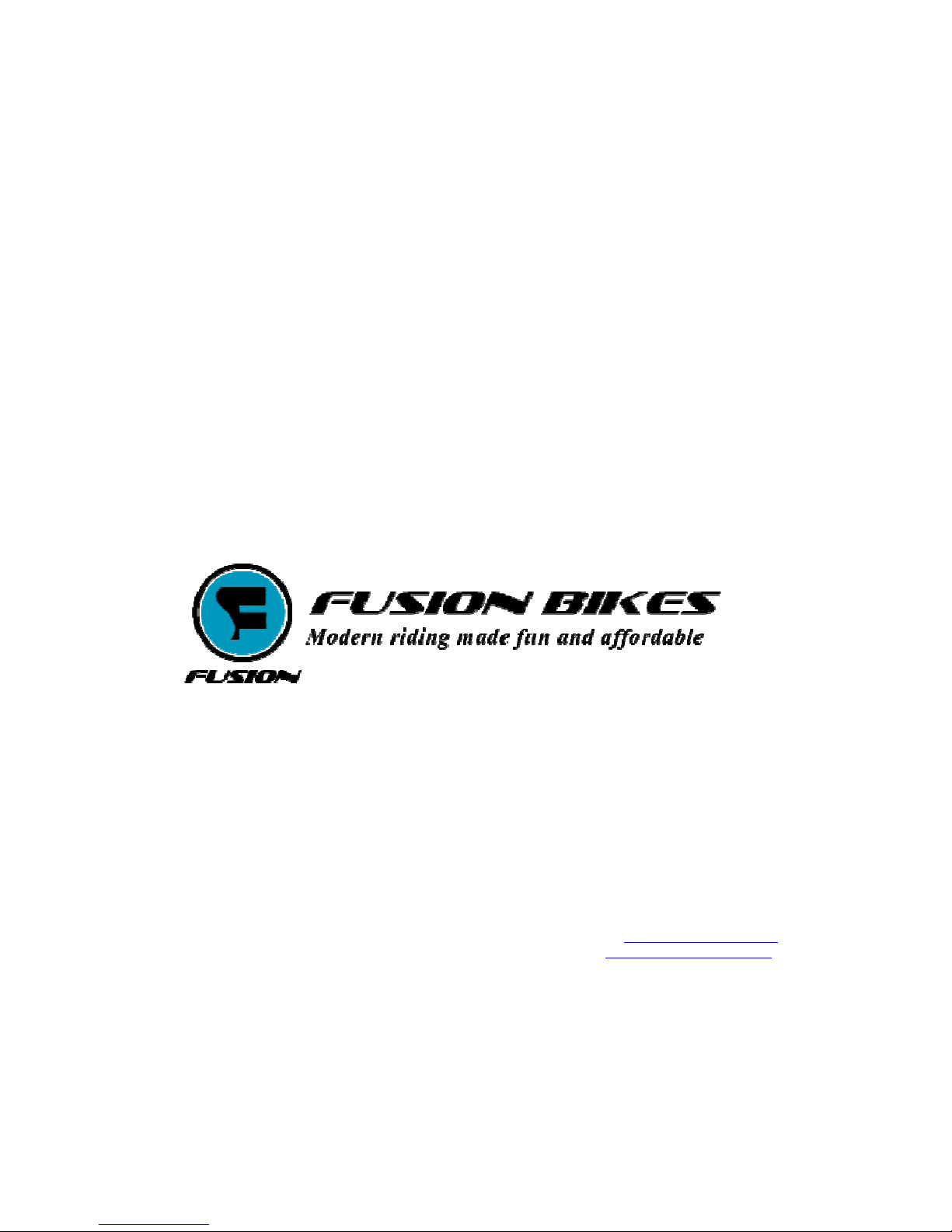
1) What is included within the box
Main bike frame with back wheel and front fork attached.
Handlebar (unfitted)
Front wheel (unfitted)
Small Brown Box containing
i. Seat Post and bar
ii. Left/Right Peddles
iii. Disc Brake Assembly Set (See separate user manual for detailed instructions)
iv. Front White Reflector
v. Rear Red Reflector
1

This page is left blank intentionally

Atilla
KinetiK
Com act
Symmetry
11

11) Final checks
Please ensure all nuts and bolts are tightened.
Congratulations. The assembly is complete. Well done!!
Please ensure you read the maintenance manual along with this instructions template for proper use of the
mountain bike. Once again thank you for your purchase and we hope you have countless hours of easy
riding with this Mountain Bike.
PS: Please don’t forget to inflate the tire.
10

(The disc brake assembly set should contain the cable wire, the round metal disc brake, the caliper mechanism, and a
pack of nuts/screws)
2) Tools required for assembly.
Before you begin, please ensure you have the following tools. These tools will be required in the
assembly process.
Full set of allen keys
Phillip head screwdriver
Pair of Pliers
Wrench
Pair of wire clippers
Torque wrench
As a general guide, the assembly should take 45 minutes to an hour depending on individual knowledge
and previous assembly experience. Again, we strongly recommend you take it to a professional for proper
assembly if you are not comfortable with the process.
WARNING: IN THE INTERESTS OF SAFET IT IS
RECOMMENDED THAT OU HAVE THIS BIC CLE
ASSEMBLED B A SKILLED BIC CLE MECHANIC
3
Stem
Front Wheel
Peddles
Crank
Handlebar

Let’s get started …….
3) Attaching the Handlebar to the Stem of frame.
Now that we have the right tools, let begin by removing the bike out of the box. Set the main bike frame on
a flat surface such that it is balanced. This will allow us to connect the handlebar to the stem of the main
bike frame with ease.
The handlebar should be loosely dangling. This needs to be connected to the main bike frame. Before you
begin to tighten the handle bar to the stem, please determine if you prefer to have the stem facing down or
facing up. By default, the stem has been set up facing down.
If the stem is facing down, this allows the handlebar to be closer to the ground and therefore a
lower ride. (option 1)
If you prefer the handlebar to be closer to your upper body and a more comfortable ride, we
recommend you have the handle bar facing up (option 2)
If you decide to set up the stem facing down, please ignore the following steps (a-g).
If you decide set up the stem facing up, please follow the following steps
a. Remove the rubber seal to expose the top nut.
b. Loosen the top nut using the allen key.
c. Loosen the side nuts using the allen key 4
Stem
Handlebar
Top
Nut
Side
Nut

Fig 1 Fig 2
Fig 3
10) Fit the front and rear reflectors to the bike
The red reflector is to be attached to the rear end on the seat post.
The white reflector is to be attached to the front end on the handlebar. You will need a Philips head
screwdriver for this part of the assembly.
9
Pull down, then lock the wire
into position by adjusting the
nut in the disc brake Clip
access wire and cap the end

Incorrect quick-release use is dangerous because these mechanisms hold the wheels in place. The most
common mistake is simply turning the lever like a nut until the wheel seems tight. Used this way the lever
and wheel can loosen as you ride.
9) Adjusting the brake lever and tightening the brakes
Step 1: Pull the brake handle so that the slot in section is exposed
Step 2: Take the brake cable. Using the hammer shaped side, fit the cable into the slot. You might need to
adjust the screw caps such that the opening is aligned (see fig 2)
Step 3: Once the cable is in, screw the caps such that the open is no longer aligned (to prevent cable from
coming out)
Step 4: Now slip the other side of the cable wire through the disc brake lever. (see Zoom instruction set for
further details)- Fig 3
Step 5: Hold the end of the cable, and pull the plastic/rubber cover as much as you can into the handlebar
brake lever.
Step 6: Using a pair of pliers, take firm hold of the cable on the disc brake end and pull downwards.
Step 7: Keeping the tension, secure the cable onto the disc brake by using an Allen Key to lock the cable
(see Zoom instruction set for details)
Step 8: Using a pair of clippers, clip off any wire.
Step 9: Cap the end of the wire using the silver caps provided in the disc brake set package. Apply firm
pressure on the caps using a set of pliers to mould the silver caps into place.
8

d. Slide the stem up to remove it from the main frame
e. Flip the stem upside down.
f. Re-attach the stem be tightening the top and side nuts using your allen key.
g. Place the rubber seal back over the top nut.
Align the handlebar such that the centre point is in the middle of the stem. Once you are happy with the
positioning, using the centre plates, tighten the handlebar to the stem using the Allen key and screwing the
nuts into position.
4) Attaching the metal disc brake to the front wheel
- please refer to the Disc brake assembly instructions
5) Attach the brake set to the front fork
- please refer to the Disc brake assembly instructions
5
Centre
plates

6) Attach the seat ost to the frame
Remove the seat and the bar from the package. Slide the indented side of the bar into the seat. Adjust the
position of the seat by tilting it up or down to your own comfort level. Tighten the seat post by adjusting
the nuts using a wrench. Make sure the nuts are tight or the seat will give once you body weight is on the
seat.
Once the seat is attached to the bar, you can slide it into the frame. Adjust the height of the bar to your own
riding height. Please see the user guide for your correct riding height. To secure the seat post in place,
please use the adjustable latch. The adjustable latch can be tightened by screwing clockwise (anti-clockwise
to loosen) and then by locking it into place at the appropriate tightness.
6

7) Attach the edals to the Crank Set
The pedals are designated left and right. The left pedal is to be attached to the left side of the crank. The
right pedal is to be attached to the right side of the crank.
To secure the pedals, please use a wrench to tighten it to the crank set.
8) Attach the front wheel to the fork
If you have attached the metal disc brake to the front wheel (as per the “Zoom” brakes instruction manual)
and the disc brake to the fork, you may now proceed to slide the wheel into position. Locate the Quando
quick release skewer. Slide the skewer in between the wheel axle, firstly by loosening the cap screw. Once
the skewer is though the wheel, you can screw back the cap on. Do not screw the cap too tightly at this
stage as further adjustments are required later.
Now rest the fork on the protruding ends of the skewer. There should be no need to force the fork into
place. If there is not enough protruding space to fit the fork, please loosen the cap. The metal disc brake
should also fit naturally with ease in between the gap of the disc brake set.
With the wheel centered in the fork (or frame), adjust the quick release by opening it, holding both ends
and turning one clockwise until, when you close the lever, you feel some resistance. At this point, try to
close the lever. The adjustment is correct when you can fully close the lever (animation) but with some
effort (the lever should leave its impression in the palm of your hand). If you can only close the lever part
way, open it, unscrew the adjustment slightly and try again.
7
This manual suits for next models
7
Other Fusion Bikes Bicycle manuals