Thank you for purchasing a Futaba FHSS 3PRKA 2.4GHz system.
This system is based on the combination of the newly developed 2.4GHz transmitter and
its corresponding receiver. Before using your 3PRKA 2.4GHz system, read this manual
carefully and use your R/C set safely.
After reading this manual, store it in a safe place.
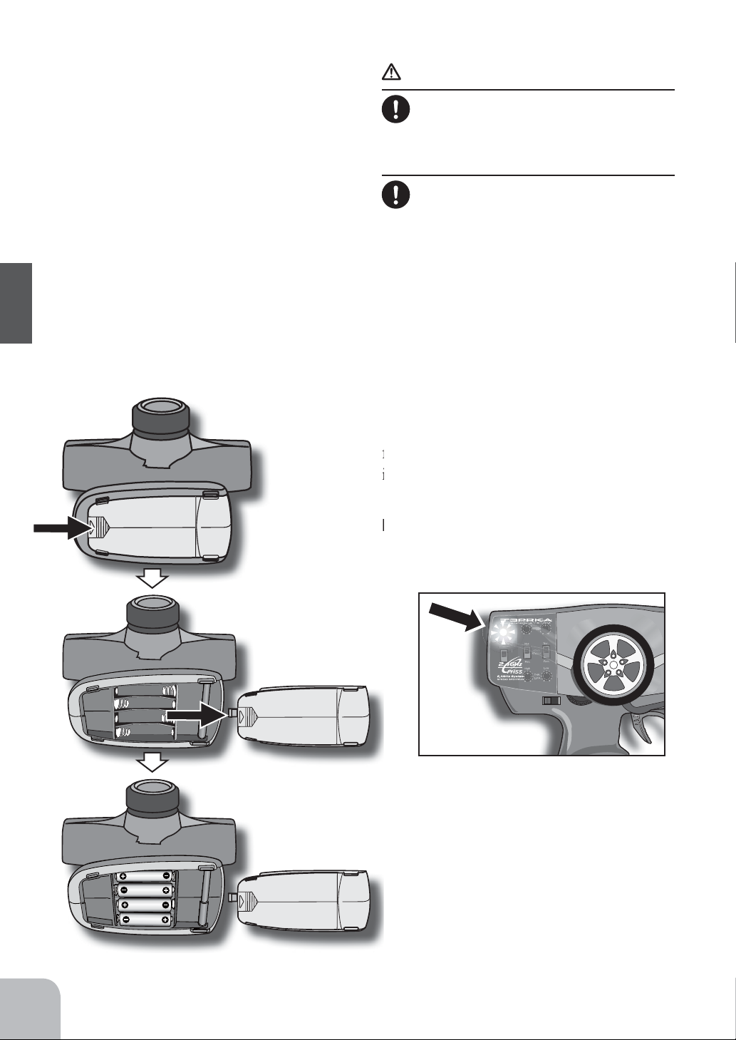
FHSS 3PRKA 2.4GHz system
system minimizes the interference from other 2.4GHz systems.
system is not compatible with FASST.
control of models for hobby and recreational purposes.
outside your country, and not the authorized Futaba distributor in your country, please contact the seller
immediately to determine if such export regulations have been met.
and an application for export approval must be submitted.
warranty.
Compliance Information Statement (for U.S.A.)
This device, trade name Futaba Corporation of America, model number R203GF, complies with part 15 of
operation.
Battery Recycling (for U.S.A.)
The RBRCTM
products indicates that Futaba Corporation of America is voluntarily participating in an
industry program to collect and recycle these batteries at the end of their useful lives, when
TM program provides a convenient
illegal in some areas.
You may contact your local recycling center for information on where to return the spent battery. Please
of America's involvement in this program is part of its commitment to protecting our environment and
conserving natural resources.
RBRCTM is a trademark of the Rechargeable Battery Recycling Corporation.