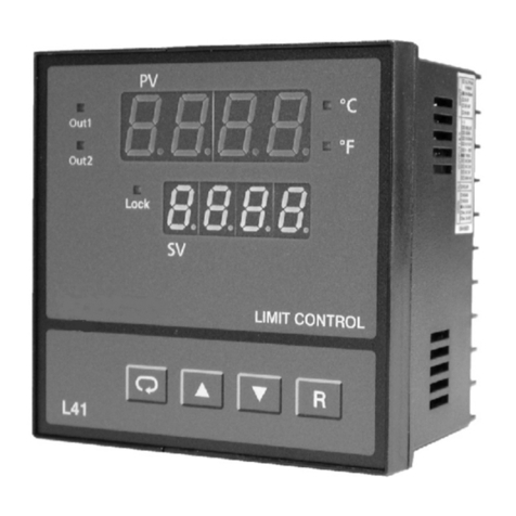
futuredesion L22 User manual

UML0621B
April 2023
PROCESS LIMIT CONTROLLER
L22/L62/L42
USER MANUAL

L22/L62/L42 Process Limit Control
2
Preface
Future Design Controls Inc. (herein referred to as FDC) reserves the right to change information available
in this document without notice. FDC is not liable for any damages incurred to equipment and/or personnel
during installation or use of the L22, L62 or L42 process limit control as explained in this document. The
end user must acquire sufficient knowledge and skill set prior to using the process limit control in the
application and follow all the local standards and regulations to meet all applicable safety requirements.
Revision History
Version
Description
Date
UM0L621A
Initial Release
February, 2022
UM0L621B
Power-Up Mode Addition
April, 2023
Safety Information in this Manual
Notes, cautions and warnings appear throughout this book to draw your attention to important operational
and safety information.
A “NOTE” marks a short message to alert you to an important detail.
A “CAUTION” appears with information that is important for protecting your equipment and ensuring
performance.
A “WARNING” appears with information that is important for protecting you, others and equipment from
damage. Pay very close attention to all warnings that apply to your application.
This symbol (an exclamation point in a triangle) precedes a general CAUTION or WARNING
statement.
This symbol (a lightning bolt in a lightning bolt in a triangle) precedes an electric shock
hazard CAUTION or WARNING safety statement.
Copyright
The documentation and the software included with this product are copyrighted 2022 by FDC, all rights are
reserved. No part of this manual may be reproduced/copied/translated or transmitted in any form or by any
means without the prior written permission of FDC.
Contact Information
Future Design Controls, Inc.
7524 West 98th Place, P.O. Box 1196
Bridgeview, IL 60455 USA
888.751.5444 - Office:
888.307.8014 - Fax
866.342.5332 - Technical Support
E-mail: csr@futuredesigncontrols.com
Website: http://www.futuredesigncontrols.com

L22/L62/L42 Process Limit Control
3
TABLE OF CONTENTS
1 Introduction ................................................................................................................5
1.1 Why Use a Limit Control?..........................................................................................5
1.2 Features....................................................................................................................5
1.3 Specifications............................................................................................................6
1.4 Ordering Code...........................................................................................................9
1.4.1 L42 Ordering Code ..........................................................................................................................9
1.4.2 L62 Ordering Code ........................................................................................................................10
1.4.3 L22 Ordering Code ........................................................................................................................11
1.4.4 Accessories ...................................................................................................................................11
1.4.5 Related Products ...........................................................................................................................11
1.5 Programming Port...................................................................................................12
1.6 Keys and Displays...................................................................................................13
1.6.1 Keypad Operation..........................................................................................................................14
1.6.2 Display Operation ..........................................................................................................................15
1.7 Menu Navigation .....................................................................................................16
1.7.1 User Access Menu.........................................................................................................................17
1.7.1.1 Reference Data ......................................................................................................................17
1.7.2 Setup Menu ...................................................................................................................................18
1.7.2.1 Basic Menu (bASE)................................................................................................................19
1.7.2.2 Communication Menu (CoMM) ..............................................................................................20
1.7.2.3 User Select Menu (SEL).........................................................................................................20
1.7.2.4 Event Input Menu (EI) ............................................................................................................21
1.7.2.5 Alarm Menu (ALRM)...............................................................................................................21
1.7.2.6 Output Menu (OUT)................................................................................................................22
1.7.3 Calibration Menu............................................................................................................................23
1.8 Parameter Availability..............................................................................................24
1.9 Parameter Description.............................................................................................26
2 Installation and Wiring.............................................................................................32
2.1 Enclosure Guidelines ..............................................................................................32
2.2 Mounting .................................................................................................................32
2.2.1 L42 Dimensions.............................................................................................................................33
2.2.2 L62 Dimensions.............................................................................................................................34
2.2.3 L22 Dimensions.............................................................................................................................35
2.3 Wiring Precautions..................................................................................................36
2.3.1 L42 Terminal Connections.............................................................................................................36
2.3.2 L62 Terminal Connections.............................................................................................................37
2.3.3 L22 Terminal Connections.............................................................................................................37
2.4 Power Wiring...........................................................................................................38
2.5 Sensor Installation...................................................................................................38
2.5.1 Sensor Input Wiring.......................................................................................................................39
2.6 Limit Control Output Wiring.....................................................................................40
2.7 Alarm Wiring............................................................................................................41
2.7.1 Alarm 1 (Output 2) .........................................................................................................................41
2.7.2 Alarm 2...........................................................................................................................................41
2.7.3 Alarm 3...........................................................................................................................................41

L22/L62/L42 Process Limit Control
4
2.8 Event Input Wiring...................................................................................................42
2.9 Retransmission Wiring ............................................................................................42
2.10 RS-485 Serial Communication Wiring...................................................................43
3 Configuration............................................................................................................44
3.1 Security...................................................................................................................44
3.1.1 Calibration Security........................................................................................................................45
3.2 Input Settings ..........................................................................................................45
3.2.1 Digital Filter....................................................................................................................................46
3.2.2 User Calibration (PV Offset)..........................................................................................................47
3.3 Limit (Output 1) Settings..........................................................................................48
3.4 Output 2 (Limit Annunciator/Alarm).........................................................................49
3.5 Alarm Settings.........................................................................................................49
3.6 User Select Menu Settings......................................................................................51
3.7 Display Mode ..........................................................................................................51
3.8 Power Up Mode.......................................................................................................52
3.9 Communication Settings .........................................................................................53
3.10 Retransmit Settings...............................................................................................54
3.11 Event Input Settings..............................................................................................54
3.12 Limit Control Option Settings.................................................................................55
4 Calibration ................................................................................................................57
4.1 Manual Calibration Procedure.................................................................................57
4.1.1 Calibrate Thermocouple Input .......................................................................................................57
4.1.1.1 Calibrate Gain of Cold Junction Compensation.....................................................................58
4.1.2 Calibrate RTD Input.......................................................................................................................59
4.1.3 Calibrate Linear Voltage Input.......................................................................................................59
4.1.4 Calibrate Linear Current Input .......................................................................................................59
5 Communication........................................................................................................60
5.1 Functions Supported...............................................................................................60
5.1.1 Function Code 03: Read Holding Registers..................................................................................60
5.1.2 Function Code 06: Preset Single Register ....................................................................................61
5.1.3 Function Code 16: Preset Multiple Registers................................................................................61
5.2 Exception Responses..............................................................................................62
5.3 Parameter Mapping.................................................................................................62
5.4 Operational Mode and Alarm Status .......................................................................62
5.5 Process Value Scaling ............................................................................................63
5.6 Special Command Codes........................................................................................64
5.6.1 Reset Command............................................................................................................................64
5.6.2 Unlock Command ..........................................................................................................................64
5.6.3 Calibrate Input Command..............................................................................................................65
7 Error Codes and Troubleshooting ..............................................................................66
8 State of California Proposition 65 Warning.................................................................67
9 Warranty & Limitations...............................................................................................68

L22/L62/L42 Process Limit Control
5
1 Introduction
The L22, L62 and L42 are FM Approved process limit controls that can be configured either as a high limit,
a low limit or both a high and low limit control.
The limit controls can be powered by either an 11-26 or 90-250 VDC / VAC supply, incorporating a 2 ampere
(resistive) relay output as standard. An optional second output can be used as an annunciator output or as
a separate process alarm. Additional options (depending upon limit control model) include two event inputs,
up to 3 alarm outputs, RS485 communications and retransmit output. Each limit control model features a
universal programmable input with and 18-bit high resolution A to D converter. A fast-sampling rate allows
the process limit controls to respond and protect fast moving processes.
Model No.
Mounting Type
DIN Size
Dimensions
L x W x D (mm)
Depth behind
Panel (mm)
L22
DIN Rail
-
22.5 x 96 x 80
-
L62
Panel Mount
1/16 DIN
48 x 48 x 59
50
L42
Panel Mount
1/4 DIN
96 x 96 x 59
50
1.1 Why Use a Limit Control?
When a temperature control is maintaining the temperature of a furnace or other heating device for example,
a malfunction in the temperature control may result in a rise in furnace temperature resulting in damage to
the heated product or the furnace itself. When a separate process limit control is incorporated into the
control system design, if the temperature rises above the pre-set limit temperature, the limit output will open,
and the heater system circuit can be shut down to disable the heat source. In addition, the limit output will
remain open even when the temperature returns to the normal range requiring the unit to be manually reset.
A manual reset is required for safety limits. This prevents the system from repeatedly restarting without
user intervention as subsequent temperature excursions (in the example above) could result in product or
system damage. The process limit controls also offer low limit operation so that the limit function operates
when the temperature falls below the limit setting value (cooling application).
When an input error occurs, the limit output will open regardless of low or high limit operation to disable the
system and will remain in this condition until the sensor error is corrected and a manual reset is provided.
1.2 Features
The new generation of process limit controls offer a set of unique features including:
•High brightness LCD display
•Universal Input (linear voltage/current, thermocouple and RTD)
•High accuracy 18-Bit A to D input conversion (true 0.1°F resolution for T/C and RTD sensors)
•Fast input sampling rate of 200 msec
•Advanced power-up modes (normal, reset, normal-latch)
•Bidirectional menu navigation
•Direct DIN rial mounting (L22 model only)
•Micro USB programming port (for firmware upgrades and configuration capabilities)
•Up to two event inputs (remote reset/lock, switch limit set points and more)
•Up to three additional process alarm outputs (in addition to primary limit output)
•Optional RS-485 serial communications
•Optional analog retransmit with 15-bit D to A convert for accurate liner current or voltage output

L22/L62/L42 Process Limit Control
6
1.3 Specifications
Specification
L22
L62
L42
Power Supply
90 to 250VAC, 47 to 63Hz, 20 to 28 VAC,47-63Hz / 11 to 40 VDC
Power Consumption
8VA, 4W Maximum
10VA, 5W Maximum.,
12VA, 6W Maximum
Over Voltage
Category
II
Signal Input
Type
Thermocouple (J, K, T, E, B, R, S, N, L, U, P, C, D), RTD (PT100(DIN), PT100(JIS))
Current(mA), Voltage (V, mV)
Resolution
18 Bits
Sampling Rate
5 Times / Second (200msec)
Maximum Rating
-2VDC minimum, 12VDC maximum
Input
Characteristics
Type
Range
Accuracy @ 25°C
Input
Impedance
J
-120°C to 1000°C ( -184°F to 1832°F)
±2°C
2.2 MΩ
K
-200°C to 1370°C (-328°F to 2498°F)
±2°C
2.2 MΩ
T
-250°C to 400°C ( -418°F to 752°F)
±2°C
2.2 MΩ
E
-100°C to 900°C ( -148°F to 1652°F)
±2°C
2.2 MΩ
B
0°C to 1820°C (32°F to 3308°F)
±2°C (200°C to 1800°C)
2.2 MΩ
R
0°C to 1767.8°C (32°F to 3214°F)
±2°C
2.2 MΩ
S
0°C to 1767.8°C (32°F to 3214°F)
±2°C
2.2 MΩ
N
-250°C to 1300°C ( -418°F to 2372°F)
±2°C
2.2 MΩ
L
-200°C to 900°C ( -328°F to 1652°F)
±2°C
2.2 MΩ
U
-200°C to 600°C (-328°F to 1112°F)
±2°C
2.2 MΩ
P
0°C to 1395°C (32°F to 2543°F)
±2°C
2.2 MΩ
C
0°C to 2300°C (32°F to 4172°F)
±2°C
2.2 MΩ
D
0°C to 2300°C (32°F to 4172°F)
±2°C
2.2 MΩ
PT100(DIN)
-210°C to 700°C ( -346°F to 1292°F)
±0.4°C
1.3KΩ
PT100(JIS)
-200°C to 600°C ( -328°F to 1112°F)
±0.4°C
1.3KΩ
mA
-3mA to 27mA
±0.05%
2.5Ω
VDC
-1.3VDC to 11.5VDC
±0.05%
1.5MΩ
mV
0 to 50mV
±0.05%
2.2 MΩ
Temperature Effect
1.5µV /°C for all inputs except mA input, 3.0µV /°C for mA
Sensor Lead
Resistance Effect
Thermocouple: 0.2 µV /°Ω; 3-wire RTD: 2.6°C /Ω of Difference of Resistance of two leads
2-wire RTD: 2.6°C /Ω of Sum of Resistance of two leads
Burn-out Current
200nA
CMRR
120 dB
NMRR
55 dB
Sensor Break
Detection
Sensor open for Thermocouple, RTD and mV inputs, Sensor short for RTD input,
Below 1mA for 4-20mA input, Below 0.25VDC for 1 - 5VDC input, Not available for other inputs.
Sensor Break
Response Time
Within 4 seconds for Thermocouple, RTD and mV inputs, 0.1 second for 4-20mA and 1 - 5VDC inputs.
Digital Filter
Function
First Order
Time Constant
0, 0.2, 0.5, 1, 2, 5, 10, 20, 30, 60 seconds (programmable)
Event Input
Number of Event
Inputs
1
2
2
Logic Low
-10VDC minimum, 0.8VDC maximum.
Logic High
2VDC minimum, 10VDC maximum
Functions
Remote Lock, Remote Reset Output1, HSP2, LSP2, HLS2, HSP3, LSP3, HLS3, Reset Alarm1, Reset
Alarm2, Reset Alarm 3, Reset All Alarms, Cancel Latch, Reset Reference data
Output 1
Limit Control
Function
High Limit, Low Limit and High / Low Limit
Type
Relay, Source Voltage

L22/L62/L42 Process Limit Control
7
Specification
L22
L62
L42
Relay Type
Form A
Relay Rating
2A, 240VAC, 200000 Life Cycles for Resistive Load
Sourced Voltage
5VDC/30mA, Current Limiting Resistance 66Ω, 14VDC/40mA
Output 2 / Alarm 1
Limit Control
Function
Annunciator
Type
Relay, Source Voltage
Relay Type
Form A
Relay Rating
2A,240V AC,200000 Life Cycles for Resistive Load
Sourced Voltage
5VDC/30mA, Current Limiting Resistance 66Ω, 14VDC/40mA
Alarm 2 and Alarm 3
Relay Type
Form A
Maximum Rating
2A, 240VAC, 200000 Life Cycles for Resistive Load
Alarm Functions
Process High, Process Low
Alarm Mode
Normal, Latching, Normal Reverse, Latching Reverse
Data Communication
Interface
RS485 (serial)
Protocol
Modbus RTU (slave)
Address
1 to 247
Baud Rate
2400, 4800, 9600, 14.4K, 19.2K, 28.8K, 38.4K, 57.6K, 115K (programmable)
Parity Bit
None, Even or Odd
Stop Bit
1
Data Length
8
Communication
Buffer
160 Bytes
Analog Retransmission
Output Signal
4-20mA, 0-20 mA,0 - 10VDC
Resolution
15 Bits
Accuracy
±0.05% of Span ± 0.0025% / °C
Load Resistance
0 to 500Ω for current output, 10KΩ minimum for Voltage Output
Output Regulation
0.01% for full load change
Output Setting Time
0.1Second (stable to 99.9%)
Isolation Breakdown
1000VAC min
Integral Linearity
Error
±0.005% of span
Temperature Effect
±0.0025% of span /°C
Saturation Low
0mA or 0VDC
Saturation High
22.2mA or 5.55V,11.1V min
Linear Output
Ranges
0 - 22.2mA (0 - 20mA/4 - 20mA), 0 - 5.55VDC (0 - 5VDC, 1 - 5VDC), 0 - 11.1VDC (0 - 10VDC)
User Interface
Keypad
4 Keys
Display Type
4 Digit LCD Display
No of Display
2
Upper Display Size
0.31” (8mm)
0.58” (15mm)
0.98” (25mm)
Lower Display Size
0.25” (6.5mm)
0.3” (7.8mm)
0.55” (14mm)
Programming Port
Interface
Micro USB
PC Communication
Function
Firmware upgrade
Environmental and Physical Specifications
Operating
Temperature
-10°C to 50°C
Storage
Temperature
-40°C to 60°C
Humidity
0 to 90 % RH (Non-Condensing)

L22/L62/L42 Process Limit Control
8
Specification
L22
L62
L42
Altitude
2000 Meters Maximum
Pollution
Degree II
Insulation
Resistance
20MΩ Minimum (@500V DC)
Dielectric Strength
2000VAC,50/60 Hz for 1 Minute
Vibration
Resistance
10 to 55 Hz, 10m/s2 for 2 Hours
Shock Resistance
200 m/s2 (20g)
Housing
Flame Retardant Polycarbonate
Mounting
DIN-Rail
Panel
Panel
DIN Size
-
1/16
1/4
Dimensions
(W*H*D) (mm)
22.5*96*83
48*48*59
96*96*59
Depth Behind Panel
(mm)
-
50
50
Cut Out Dimensions
(mm)
-
45*45
92*92
Weight (grams)
160
160
290
Approval Standards
Safety
FM Class 3545, UL61010-1, CSA 22.2 No.61010-1-12, EN61010-1 (IEC1010-1), ROHS, REACH
Protective Class
IP50 for the front panel, IP20 for rear terminals and housing. All indoor use.
EMC
EN61326

L22/L62/L42 Process Limit Control
9
1.4 Ordering Code
1.4.1 L42 Ordering Code
FDC - L42 -
Power Input
4: 90 to 250 VAC, 47-63Hz
5: 20 to 28 VAC, 47-63Hz / 11 to 40 VDC
Output 1
1: Form A Relay (2A, 250V)
2: SSRD, 5VDC/30mA (33Ω, ¼W *2)
C: SSRD, 14VDC/40mA (OM94-7)
Output 2 / Alarm 1
0: None
1: Form A Relay (2A, 250V)
2: SSRD, 5VDC/30mA (33Ω, ¼W *2)
C: SSRD, 14VDC/40mA (OM94-7)
Alarm 2 to 3
0: None
1: Form A Relay on Alarm 2 (2A, 250V)
2: Form A Relay on Alarm 2 to 3 (2A, 250V)
Event Inputs
0: None
1: 2 Event Inputs
Option 1
0: None
1: RS485 Modbus RTU Serial Communications
Option 2
0: None
Option 3
0: None
1: Retransmission 4-20mA/0-20mA (CM98-3)
2: Retransmission 0-10VDC (CM98-5)
Option 4
0: None
1: Terminal Cover
Special Code
Standard leave blank
Special order AA-ZZ

L22/L62/L42 Process Limit Control
10
1.4.2 L62 Ordering Code
FDC - L62 -
Power Input
4: 90 to 250 VAC, 47-63Hz
5: 20 to 28 VAC, 47-63Hz / 11 to 40 VDC
Output 1
1: Form A Relay (2A, 250V)
2: SSRD, 5VDC/30mA (33Ω, ¼W *2)
C: SSRD, 14VDC/40mA (OM94-7)
Output 2 / Alarm 1
0: None
1: Form A Relay (2A, 250V)
2: SSRD, 5VDC/30mA (33Ω, ¼W *2)
C: SSRD, 14VDC/40mA (OM94-7)
Alarm 2
0: None
1: Form A Relay (2A, 250V)
Option 1
0: None
1: RS485 Modbus RTU Serial Communications
Option 2
0: None
1: 2 Event Inputs
Option 3
0: None
1: Retransmission 4-20mA/0-20mA (CM98-3)
2: Retransmission 0-10VDC (CM98-5)
3: Alarm 3 Form A relay (2A, 250V)
Option 4
0: None
1: Terminal Cover
Special Code
Standard leave blank
Special order AA-ZZ

L22/L62/L42 Process Limit Control
11
1.4.3 L22 Ordering Code
FDC - L22 -
Power Input
4: 90 to 250 VAC, 47-63Hz
5: 20 to 28 VAC, 47-63Hz / 11 to 40 VDC
Output 1
1: Form A Relay (2A, 250V)
2: SSRD, 5VDC/30mA (33Ω, ¼W *2)
C: SSRD, 14VDC/40mA (OM94-7)
Output 2 / Alarm 1
0: None
1: Form A Relay (2A, 250V)
2: SSRD, 5VDC/30mA (33Ω, ¼W *2)
C: SSRD, 14VDC/40mA (OM94-7)
Option 1
0: None
1: RS485 Modbus RTU Serial Communications
2: 1 Event Input (EI1)
Option 2
0: None
1: Retransmission 4-20mA/0-20mA (OM98-3)
2: Retransmission 0-10VDC (OM98-5)
3: Alarm 2 Form A relay (2A, 250V)
4: 1 Event Input (EI2)
Special Code
Standard leave blank
Special order AA-ZZ
1.4.4 Accessories
OM94-7 14VDC/40mA SSR Drive Module
OM98-3 Isolated 4-20mA/0-20mA Retransmission Module for L22
OM98-5 Isolated 0-10VDC Retransmission Module for L22
CM98-3 Isolated 4-20mA/0-20mA Retransmission Module for L62 and L42
CM98-5 Isolated 0-10VDC Retransmission Module for L62 and L42
PA98-1 USB Programming Adaptor
CC98-1 Programming Port Cable (1.5m)
1.4.5 Related Products
SNA10A Smart Network Adaptor for third party software (converts RS232 to RS422/485)
FDC-Set Configuration Software

L22/L62/L42 Process Limit Control
12
1.5 Programming Port
A Micro USB Port provided on the limit control can be used to connect it to a PC by using a programming
port cable (CC98-1) and adapter (PA98-1) for firmware updates.
Micro USB Programming Port
Rear Terminals Front Panel
The limit control will be powered via the USB port adapter when connected to a PC so separate power is
not required. The programming port is used for off-line automatic setup and testing procedures only. By
using PC programming software such as FDC-Set, you can save limit configurations to a file and then
download them to the limit control eliminating the need to manually enter settings on every unit.
Note: Do not attempt to make any connections to this port while the limit control is under normal operation.
Programming Port Cable (CC98-1)
Programming
Adapter (PA98-1)

L22/L62/L42 Process Limit Control
13
1.6 Keys and Displays
The following figures depict the interface arrangement for each of the process limit control models.
L62 Front Panel Keys and Display
L22 Front Panel Keys and Display

L22/L62/L42 Process Limit Control
14
L42 Front Panel Keys and Display
1.6.1 Keypad Operation
SCROLL KEY:
This scroll key is used to select a parameter to be viewed and/or adjusted as well as navigate to the
next parameter. Repeatedly pressing and releasing the key advances through each available
parameter under the current menu. Once the last parameter under the menu is reached, it will loop
back to the first value. Pressing and releasing the scroll key at the same time as the up key will advance
to the previous parameter. This provides the ability to scroll back to the previous parameter without
having to advance all the way through the menu and back to the beginning,
The scroll key also acts as an ENTER key. This is done by pressing and holding the key for a specific
amount of time. It provides access to the various menus including setup and calibration. See section
1.7 Menu Navigation.
UP KEY:
This key is used to increase the value of the selected parameter.
DOWN KEY:
This key is used to decrease the value of the selected parameter.
RESET KEY:
This key is used to:
1. Revert the display to the home screen.
2. Reset a latching alarm once the alarm condition is removed.
3. Reset the limit condition after the process is within the limit set point.
4. Reset the limit annunciator.

L22/L62/L42 Process Limit Control
15
Note: If the reset key is left pressed, only one reset operation will occur. If the unit subsequently
goes into a state where reset is required again, the reset key (or remote reset contacts)
must be released (opened) and pressed (closed) again.
1.6.2 Display Operation
POWER UP SEQUENCE:
During power up the following sequence will be followed.
1. All segments of the display and indicators will be off for ~4 seconds.
2. The upper display will show PRoG, and the lower display will show the model number and
firmware version for ~1.5 seconds.
3. The upper display will show bULd and the lower display will show the build number for ~1
second.
NORMAL DISPLAY:
During normal operation (non-limit condition), the unit will display the process value, and the word SAFE.
The OUT1 indicator will be off, and the output 1 contacts will be closed.
ABNORMAL DISPLAY:
Whenever the process is outside the normal range, the lower display will display the limit set point value
that has been exceeded instead of displaying the word SAFE. The OUT1 indicator will be on, and the
output 1 contacts will be open.
SENSOR BREAK DISPLAY:
If a sensor break is detected in the sensor circuit, the upper display will flash SbER. The OUT1 indicator
will also be on, and the output 1 contacts will be open.
A-D FAILURE DISPLAY:
If failure is detected in the A-D input circuit, the upper display will flash AdER. The OUT1 indicator will
also be on, and the output 1 contacts will be open.
How Characters are Displayed on the LCD Screen

L22/L62/L42 Process Limit Control
16
1.7 Menu Navigation
The process limit control provides three menu groups:
User Menu: Provides access to the low/high limit set point values, viewing of minimum
and maximum process values, time in limit condition and select parameter
values as defined in setup.
The User menu is the default (home) menu. It can be accessed when in
the Setup or Calibration menus by simply pressing the reset key.
Setup Menu: Provides access to all setup menus for configuring the limit mode of
operation, outputs, alarms and communications settings if applicable.
To access the Setup menu from the User menu, press and hold the scroll
key. After ~5 seconds, the upper display will show SET and then
immediately release the scroll key.
Calibration Mode Menu: Provides access to the input calibration parameters and functions.
To access the Calibration menu from the User or Setup menu, press and
hold the scroll key. After ~6 seconds, the upper display will show CALI
and then immediately release the scroll key.
To access parameters,
refer to section 1.71
User Access Menu.
To access parameters,
refer to section 1.72
Setup Menu.
To access parameters,
refer to section 1.73
Calibration Menu.

L22/L62/L42 Process Limit Control
17
1.7.1 User Access Menu
The user menu is the default (home) menu of the limit control. Repeatedly pressing the scroll key cycles
through the list of parameters as shown below. When scrolling through the available parameters, the upper
display will provide the parameter description, i.e., HSP1 for high limit set point 1 for example, while the
lower display will indicate the current value.
Pressing the up or down key when on an adjustable parameter such as the high limit set point, increases
or decreases the current value. Note that not all of the parameters listed may be available. The availability
of the different high and low set points and selectable parameters (SEL1 to SEL5) are dependent upon the
configuration of the limit. Therefore, the parameters are only available when the option is enabled under
the Setup menu.
1.7.1.1 Reference Data
There are three reference data parameters displayed in the user access menu. The reference data
parameters are read only. The maximum historical process value (PV.HI), indicates the maximum process
value since the last UNLOCK operation. The minimum historical process value (PV.Lo), indicates the
minimum process value since the last UNLOCK operation. The abnormal time (t.AbN), indicates the total
accumulated time (in minutes) during which the process value has exceeded the high or low limit set point
the last UNLOCK operation.
The values of the reference parameters will be cleared by pressing and holding the reset key for 4 seconds
(UNLOCK operation). After the UNLOCK operation is performed, the PV.HI and PV.Lo values will be
initialized to the current process value and t.AbN will be set to zero.
PV,SV
HSP1
LSP1
HSP2
LSP2
HSP3
LSP3
PV.HI
PV.LO
T.ABN
PASS
KPAS
SEL1
SEL2
SEL3
SEL4
SEL5

L22/L62/L42 Process Limit Control
18
1.7.2 Setup Menu
The setup menu is divided into six categories to make the configuration process easier. To access the
setup menu from the user menu, press and hold the scroll key for ~5 seconds. One the upper display
shows SEt (for setup menu), immediately release the scroll key. The lower display will then indicate one
of the six categories of the setup menu as shown below:
Basic Menu
Communication Menu
User Menu
Event Input Menu
Alarm Menu
Output Menu
Once in the setup menu, pressing the up or down key will scroll between the six categories. To cycle
through the parameters under the chosen category, repeatedly press the scroll key.
Note: The availability of certain parameters under the setup menus is dependent upon available hardware
and configuration settings. See section 1.8 Parameter Availability for a list of all the parameters
and their conditions of availability.
For a description of each of the available parameters along with their range of entry, see section
1.9 Parameter Description.

L22/L62/L42 Process Limit Control
19
1.7.2.1 Basic Menu (bASE)
Upon entering the setup menu, the upper display will show Set. To access the base menu, use the or
key to get bASE in the lower display. Then press the key to access the basic menu parameters.
The upper display will show the parameter description and the lower display will indicate the parameter
value.
Note: The availability of certain parameters under the setup menus is dependent upon available hardware
and configuration settings. See section 1.8 Parameter Availability for a list of all the parameters.

L22/L62/L42 Process Limit Control
20
1.7.2.2 Communication Menu (CoMM)
Upon entering the setup menu, the upper display will show Set. To access the communications menu, use
the or key to get CoMM in the lower display. Then press the key to access the communication
menu parameters. The upper display will show the parameter description and the lower display will indicate
the parameter value.
1.7.2.3 User Select Menu (SEL)
Upon entering the setup menu, the upper display will show Set. To access the user select menu, use the
or key to get SEL in the lower display. Then press the key to access the user select menu
parameters. The upper display will show the parameter description and the lower display will indicate the
parameter value.
SEL
5 Sec or
PV,SV SET
SEL1
SEL2
SEL3
SEL4
SEL5
This manual suits for next models
2
Table of contents
Other futuredesion Controllers manuals
Popular Controllers manuals by other brands

Douglas
Douglas WIR-3110 user manual

Emerson
Emerson PeC C100 Hardware Implementation Guidelines

Alpha Technologies
Alpha Technologies Cordex CXC HP Hardware manual

Mankenberg
Mankenberg UV 3.5 ATEX H2 Original operating manual

SMC Networks
SMC Networks HEC002-A5 Operation manual

LDA Audio Tech
LDA Audio Tech VCC-64 user manual