Fytech FY-7000 User manual

Owner’s Manual
FY-7000
The equipment is approved by following car manufacturers(China)

1、Safety Precautions Symbols
2、Symbols and Definitions
3、Accessories and Spare Parts List
4、Installation
1)、Sp ecifications
2)、D uty Cycle and Overhea ting
3)、Machine Installation
4)、Se lecting a Location
5)、Co nnecting Input Power
5、Operation
1)、Con trols
2)、Welding Gun and Adaptors
3)、Various Oper ations
a、Spo t Welding
b、Washer Welding
c、Tr iangle Washer Welding
d、Carbon Rod He ating
e、Wav e Form Wire Welding
f、Cupules
6、Ma intenance
1、Ex ploded View
2、Tr oubleshooting
7、El ectrical Diagra m
8、Pa cking List
1
2
3
4
5
6
7
8
9
10
11
12
13
14
15
16
17
18
19
Contents

Page.1
Safety Precautions Symbols
Protect yourself and others f rom inj ury,
read and follow these precaut ions be fore
installation and operatio n.
Ex p lo d ing p art s c an in jur e .Al w ays w ear a f a ce
sh i el d a nd lo ng sl e eve s。
St ati c ca n dam ag e P C bo ard s
1、Pu t on gr ou nde d wr i st s tra p be f or e
ha ndi ng b oar ds o r p ar ts。
2、Us e pro pe r sta ti c -p roo f ba g s an d box es t o
st ore,move or s hip P C bo ard s。
1、We ar ap pr ove d fa c e sh iel d or s a fe ty go gg l es
wi th si de s hie ld s。
2、We ar pr op er bo dy p r ot ect io n t o pr ote ct s k in。
Do n ot we ld i n the h ei g ht!
Read instructions.
1、Read owner's Ma nua l be for e us i ng o r ser vi c in g
un it。
2、Use only manufacturer’s supplied replacement。
Fl yin g me t al c an i n ju re ey es。
1) Wea r sa f et y gl a ss es wi th s i de s hie ld s o r fa ce
sh iel d。
1、Ma gne ti c fie ld s c an a ffe ct p a ce mak er s .
Pa cem ak er we ar e rs k eep a wa y .
2、We are rs s hou ld c o ns ult t he i r do cto r be f or e
go ing n ea r pla sm a a rc c utt in g o pe rat io n s。
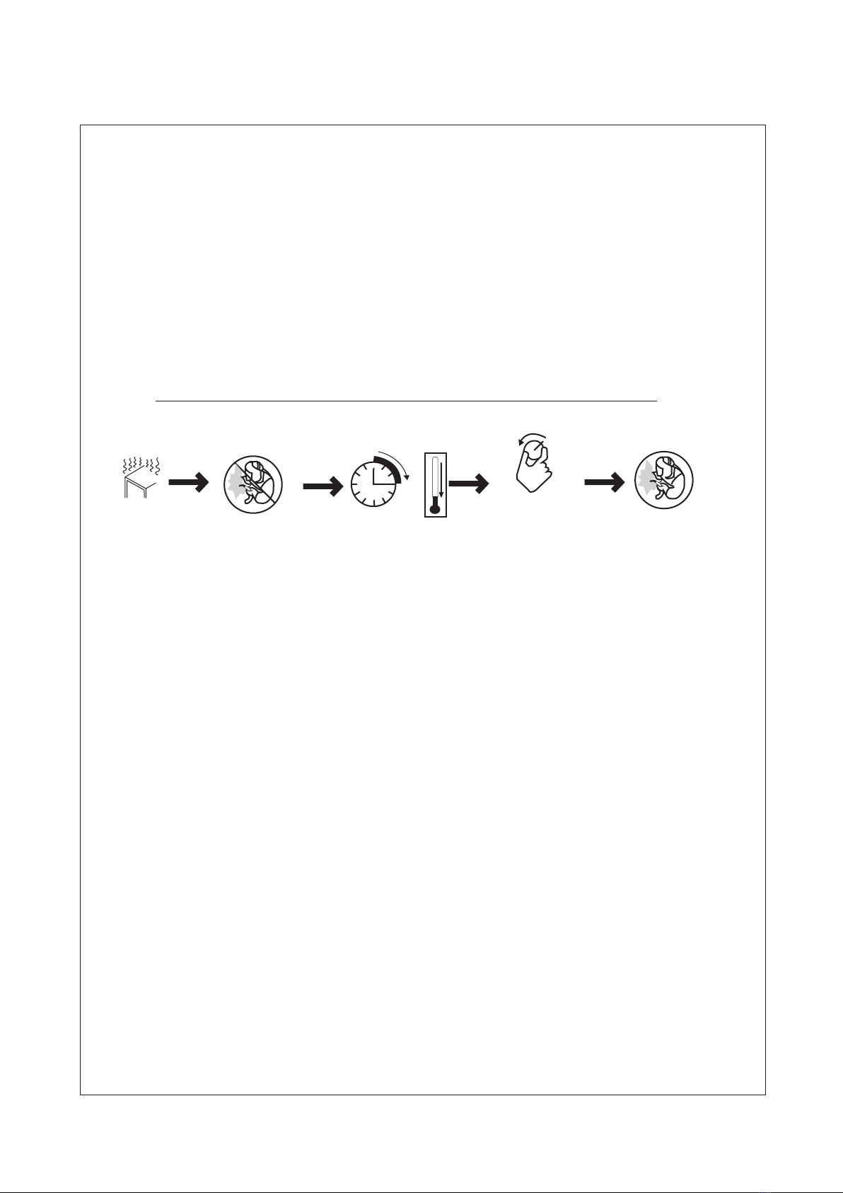
Ov e ru s e can c aus e o ver hea t in g
Al l ow c o oli ng pe r iod , fol l ow r a ted d uty c y cle
before starting to we ld ag a in.
El ect ri c sho ck c a n ki ll:
1、Do n ot to uc h liv e el e ct ric al p a rt s。
2、We ar dr y, hol e- f re e ins ul a ti ng gl ov e s an d
bo dy pr ot ect io n .
3、Do n ot wr ap e lec tr i ca l cab le a r ou nd yo ur
bo dy.
4、Gr oun d th e wor kp i ec e wit h a go o d el ect r-
ic al gr ou nd。
Ey e pro te cti on f o r we ldi ng :
Cu rre nt l eve l in a m pe rag e Mi n im um sh ad e
Nu mbe r
30-150A---------- - -- -- --- -- --- -- --- # 8
150-300A--------------------------- # 10
30 0-5 00 A-- -- ----------------------- #12
Nev er cut o n pres suri zed cy lind er.
Maintenance regularly!
Fa cto ry s afe ty!
Fi re or e xp los io n h az ard .
Do n ot lo ca te un it o n ,o ver ,o r n ea r com bu s ti be
su rfa ce s.D o no t i ns tal l un i t ne ar fl am m ab les .
Re mov e al l fla mm a bl es of t he w e ld ing a re a .
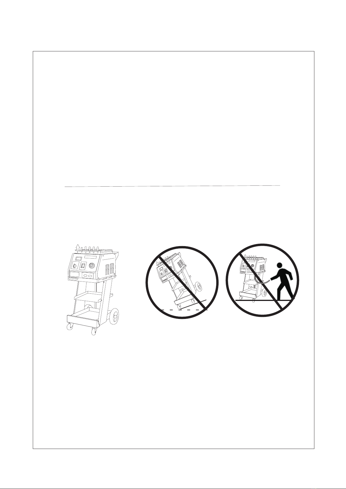
Fa lli ng u nit c an c a us e inj ur y .
Th e hea t fr om th e wo r kp iec e ca n c au se se ri o us
bu rns。
Fu mes a nd g ase s ca n b e ha zar do u s
we ldi ng p rod uc e s fu mes a nd g a se s. Breathing
th ese f um es an d ga s es c an be h az a rd ous
to y our h ea lth .
If inside,ventilate the area.
Do n ot we ld i n a con fi n ed s pac e on l y if i t
is w ell v en til at e d.
Pr ote ct y our se l f Warn others

Definitions
Symbols and Definitions
U1
U0
U2
I2
s1
HZ
A
V
Rated w e l d i n g
current
Prima r y v o l t a g e
Rated n o l o a d
volta g e ( A a v e r age)
Conve n t i o n a l
load vo l t a g e
Power rating,
product o f vo lta ge
and current(KVA)
Her tz
Amperes
Volts
IP
X
I1max
I1eff
~
1
Rated m a x i m u m
suppl y c u r r e n t
Maximum effective
supply current
De gre e of p rot ec t io n
Singl e p h a s e
Duty cycle
Direct current
Constant current
Temperature
V
S
I
O
Su ita bl e f or s om e
ha zar do u s lo ca t io ns
Volta g e i n p u t
Lo w air p re ssu re
li ght
On
Off
Protective earth
(Ground)
Input
+-
%
Adjust air/gas
pressure
Percent
Increase
Line co n n e c t i o n
Loose s h i e l d c u p
Autom a t i c
Manua l
Page.2
Do not d o this

Accessories And Spare parts
Accessories and Spare Parts List:
Waveform electrode tip
NO.F010
NO.F013
Co nt ro l tr an sf or me r
NO.F025
Pn eu m at ic v acu um c up u le
NO .F 0 01
Hook puller
NO.F004
Kriptol
NO.F007
St ud
NO.F016
Manual cupule
NO.F019
Back wheel
NO.F022
Sp ot we ld ing e le c tr ode
tip NO.F008
Washer adaptor
NO .F0 11
Fr ont p ar t of ho ok p u ll er
NO.F014
Washer
NO.F017
Welding gun
NO.F020
Pull hammer
NO.F002
Ho ok
NO.F005
Ve rti ca l spo t we l di ng
pu ll ha mm er NO .F 0 03
Waveform wire
NO.F006
Carbon rod adaptor
NO.F009
Electrode holder
NO.F012
Triangle wasler
NO.F015
Earth clamp
NO.F018
Fr ont w he el
NO.F021
Ci rcu it b oar d
NO.F028
Remark:
1)、Optionnal orders for above accessories and components are
available.
2)、Model and parts number required when ordering parts from
your local distributor.
Page.3
Trianger washer adaptor
Digitial dispiay NO. F 0 23 Time adjustment NO.F024
A.C.contactor N O .F0 2 6 Tools box NO . F0 27

Installation
Page.4
1、specifications
0-99ms
20KW
A.B.C
150kg
620*450*980
5200A
Continuity
0.8+1.0
78kg
51A
FY-7000
Single p hase
220V
50/60H z
AC6 V-10 V Carb on rod h eati ng
AC1 V-12 V Wash er fus ion
AC1 V-13 V Butt w eld
Input voltage
Output voltage
Input power
Input current
Operation way
Time regulation system
Currenf Regulafion
Vacuum cupule device
Dimension(mm)
Parameters
Instant max.current
One side welding
thickness(mm)
Weight
Model

2、Duty Cycle and Overheating
Duty cycle is percentage of 10 minutes that unit can weld at
rated load without overheating.
The welder is equipped with over-hert protection.On exceeding the
critical temperature,the welder will be stopped automaticlly.The
welder can be used again after cooling down.
Pag e .5
Overheating Sto p work ing Wai t fift een mi nute s
for u nit to c ool
Red uce am pera ge or
reduce duty cycle
Wel d a gain
0
15
A

3、Machine Installation
1)open the package and find out the owner's manual。
2)Check the supplied accessories according to packing list
that attached to this manual.
3)Properly install this equipment as following diagram.Inspect
the unit for any problems.If so,contact your local distributor
or service agency.To locate a distributor or service agency.
Page.6

Page.7
4、Selecting a Location
1)Select a correct location to place the unit.
2)Determine input power cord length according to its actual
operation requirement .Make sure that the supply cable is at
2
least 6mm indiameter
3)Do not move or operate unit where it could tip.
4)Use cart or unit handle to move unit .Do not pull the cords
to move unit.

5、Connecting Input Power
2
1、Inp ut pow er cor d(not le ss tha n 6mm
cop per co rd).
2、Ove r-cu rren t prot ecti on.
3、Dis conn ect de vice l ine te rmin als.
4、Gro und wi re L1/ L2 inp ut con duct ors.
Ins tall atio n must m eet al l Nati onal a nd
Local Codes---hav e o nly q u ali f ied p e rso n s
mak e this i nsta llat ion.
Dis conn ect an d lock out/ tago unt in put po wer
bef ore co nnec ting i nput c ondu ctor s from
unit.
Sel ect ty pe and s ize of o ver- curr ent
protection.
Clo se and s ecur e door o n disc onne ct dev ice .
Remove lockout/tagout device,and place
swi tch in t he "on" position.
4
Page.8
3
1
2
L1
L2
1

Operation
1、Controls
Page.9
1、Voltmeter
2、Current adjustment(A-Low,B-Mid,C-High)
3、Mod e
4、Tim e adju stme nt
5、Pow er switch
6、Neg ativ e outs ide wi re
7、Welding gun outp u t cab l e

2、Welding Gun and Adaptors
Page.10
1
2
1、Electrode holder
2、Trigger
Single-Sided applications
5、Tighten up the holder
4、Installed the
fixed shank
2、Put negative wire
into the welded washers
1、 Weld 2 washers
on metal
workpiece ,as close to
welding area as possible.
3、Located the holder
on the welded washers
Car bo Rod S hrin king
OT Wa sher W eldi ng
Was her We ldin g
Stud Welding
Sin gle- side d Weld ing
Wav e form W ire We ldin g
Pul ling S pot Ha mmer
Connection of negative wire

Set Mode switch
3、Operation
Con nect s pot we ldin g
electrode tip wi th wel ding
gun and tighten.
App roxi mate ly a 90°angle
to th e work epie ce sur face .
Put on pressure a nd pre ss tri gger .
F008+F020 Set c orre ct amp erag e.
Set correct time.
、
Remark:
1、Set ting a mper age to o high o r time t oo lon g can ca use wo rkpi ece su rfac e (veh icle body)damage .
Ple ase we ld oth er wor kpie ces fo r prac tice b efor e actu al ope rati ons.
2、Set ting c orre ct amp erag e and ti me acc ordi ng to th e work piec e thic knes s.
3、Con tinu ing an othe r oper atio n is app lica ble af ter th ese pr oced ures f inis hed .I f not, p leas e
shu t off th e main p ower s uppl y and sw itch o ff the unit .
Page.11
a、spot welding
ABC
Connect negative outside wire
to a clean,paint-free location
on metal workpiece,as close to
welding area as possible.
(Pos itio n C is rec omme nd).

Con nect w ashe r adap tor with
wel ding g un and t ight en,
Install washer.
Remark:
1、Set ting a mper age to o high o r time t oo lon g can ca use wo rkpi ece su rfac e (veh icle body)damage .
Ple ase we ld oth er wor kpie ces fo r prac tice b efor e actu al ope rati ons.
2、Set ting c orre ct amp erag e and ti me acc ordi ng to th e work piec e thic knes s.
3、Con tinu ing an othe r oper atio n is app lica ble af ter th ese pr oced ures f inis hed .i f not, p leas e
shu t off th e main p ower s uppl y and sw itch o ff the u nit.
F017+F011+F020
b、Washer Welding
Set c orre ct tim e.
Set c orre ct amp erag e.
3、Operation
Page.12
ABC
Set Mode switch
Connect negative outside wire
to a clean,paint-free location
on metal workpiece,as close to
welding area as possible.
App roxi mate ly a 90° angl e to the
dent.Put o n pres sure a nd pre ss
trigger.
Rem ove we ldin g gun.H ook th e wash er wit h
pul l hamm er.Sl ide th e hamm er to op posi te
dir ecti on to pu ll out t he den t .
(Pos itio n A orB is recommend) .

Con nect t rian gel wa sher
pul l hamm er wit h weld ing gu n.
Sli de the h amme r to opp osit e
direction to pul l the de nt
F003+F020
c、Triangle Washer Welding
Set c orre ct tim e.
Set correct amperage.
App roxi mate ly a 90° a ngle t o
the d ent, put on p ress ure
and p ress t rigg er.
3、Operation
Remark:
1、Set ting a mper age to o high o r time t oo lon g can ca use wo rkpi ece su rfac e (veh icle body)damage .
Ple ase we ld oth er wor kpie ces fo r prac tice b efor e actu al ope rati ons.
2、Set ting c orre ct amp erag e and ti me acc ordi ng to th e work piec e thic knes s
3.Tri angl e washer welding can r epla ce washer welding.It can draw out the concavity d ire c tly
after weld ed.
4、Con tinu ing an othe r oper atio n is app lica ble af ter th ese pr oced ures f inis hed .I f not, p leas e
shu t off th e main p ower s uppl y and sw itch o ff the u nit.
Page.13
ABC
Set Mode swit c h
Connect negative outside wire
to a clean,paint-free location
on metal workpiece,as close to
welding area as possible.
(Pos itio n A is rec omme nd).

F00 7+F0 09+F 020
d、Carbon rod Heating
3、Operation
Set c orre ct amp erag e.
Set c orre ct tim e
Remark:
1、Set ting a mper age to o high o r time t oo lon g can ca use wo rkpi ece su rfac e vehi cle body)damage .
Ple ase we ld oth er wor kpie ces fo r prac tice b efor e actu al ope rati ons.
2、Set ting c orre ct amp erag e and ti me acc ordi ng to th e work piec e thic knes s.
3、Con tinu ing an othe r oper atio n is app lica ble af ter th ese pr oced ures f inis hed .I f not, p leas e
shu t off th e main p ower s uppl y and sw itch o ff the u nit..
Page.14
ABC
Set Mode switch
Connect negative outside wire
to a clean,paint-free location
on metal workpiece,as close to
welding area as possible.
Con nect c arbo n rod an d
car bon ro d adap tor wi th
wel ding g un.
Tur n carb on rod c lock wise t o heat
up th e enti re con vexi ty sur face .
Coo l the su rfac e with a w et
rag o r comp ress ed air .
(Pos itio n A is rec omme nd).

Con nect w ave form wire ele c tro d e
tip w ith we ldin g gun.
F006+F010+020
e、
3、Operation
Set c orre ct amp erag e.
Set correct time.
Remark:
1、Set ting a mper age to o high o r time t oo lon g can ca use wo rkpi ece su rfac e (veh icle b ody) dama ge .
Ple ase we ld oth er wor kpie ces fo r prac tice b efor e actu al ope rati ons.
2、Set ting c orre ct amp erag e and ti me acc ordi ng to th e work piec e thic knes s.
3、Con tinu ing an othe r oper atio n is app lica ble af ter th ese pr oced ures f inis hed .I f not ,p leas e
shu t off th e main p ower s uppl y and sw itch o ff the u nit.
Wave Form Wire Welding
Page.15
ABC
Set Mode swit c h
Connect negative outside wire
to a clean,paint-free location
on metal workpiece,as close to
welding area as possible.
Connect hook puller with p ull hammer.
Hoo k wave form wire and slide the
hammer to pull out the dent.
Place a wave form wire
horizontally on the dent.
Approximately a 90°angle
to wave form wire.Put o n
pressure andpress trigger.
(Position A is recommend).

f、Cupules
3、Operation
Page.16
Manual operating cupule:
1、Connect manual cupule with
pull hammer.
2、Push manual cupule in to lock
the cupule on the dent.
3、Slide the hammer to opposite direction
to pull the dent out.
Pneumatic vacuum cupule:
1、Connect gas/air supply with the adaptor
of cupule.
2、Open the valve ,sticking cupule to the
dent.
3、Slide the hammer to opposite direction
pull the dent out.
4、Cupule falls off when close the valve.

Maintenance
1、Exploded view
Page.17
Voltmeter
Curre n t a d j u s t m ent switch
A.C.contactor Conti o l t r a n s f o rmer
Main tr a n s f o r m e r
Contr o l c i r c u i t b oard
Lef t s ide vie w
Rig h t side vi e w

2、Troubleshooting
Reason Remedy
No welding output
(1)Conne c t e d p o w e r supply
incorrectly.
(2)Power s w i t c h i n "off"
posit i o n
(1)Connect power supply according
to manufacturer’s instructions.
(2)Place power switch in “on”
position.
Trigger not working
(1)T r igger damaged.
(2)G u n control wire brok e n .
(3)C o ntrol wire plug loo s e n .
(4)Mode sw i t c h i n i n c o rrect
position.
(1)Replace trigger.
(2)Con nect again or repla c e i f n ec-
essar y .
(3)Co n n e ct control wire plu g a g a i n .
(4)Place Mod e s witc h i n c o r r e c t p os-
ition .
(1)Aamperage too low
(2)Weld time too short.
(3)Input power cord did not
meet the requirement.
(4)Ground clamp bad contact.
(1)In c r e a s e a m p erage setting
(2)In c r e a s e t i m e setting.
(3)Re p l a c e i n p u t power cord.
(4)Ch a n g e g r o u n d clamp location.
Piercing workpiece
(1)Outpu t a m p e r a g e t oo high.
(2)Weld ti m e t o o l o n g .
(3) Bad contact of elec t r o d e t i p o r
washe r w i t h w o r k p iece.
(1)Red u c e a m p e r a ge setting.
(2)Rr d u c e w e l d t i me.
(3)Re m o v e c o a t i ng from material
reduc e a d d e d p r e s sure.
Carbon rod working
unstable
(1)Car b o n r o d o r workpiece i s d i r t y
(2)Incor r e c t a m p e r age and time
setti n g .
(1)Polish carbon rod and
workpieces before welding
(2)Set amperage and time according to
workpiece thickness.
Welder stop working
while operation
(1)Tr i g g e r p l u g l oosen.
(2)Gu n c o n t r o l w i re broken.
(3)Ov e r h e a t i n g .
(1)Ch e c k gun c o n t r o l w i r e and
trigg e r p l u g .
(2)Wait fo r t e m p e r a t ure cool down.
Maintenance
Trouble
Poor weld
.
.
Page.18
Table of contents
Other Fytech Welding System manuals

Fytech
Fytech FY-4280/2E User manual

Fytech
Fytech FY-4220/2E User manual

Fytech
Fytech FY-4DM User manual

Fytech
Fytech FY-5000 User manual

Fytech
Fytech FY-9000 User manual

Fytech
Fytech FY-8000 User manual

Fytech
Fytech FY-9G User manual

Fytech
Fytech FYMIG306L User manual

Fytech
Fytech FYMIG306XL User manual

Fytech
Fytech FY-91G User manual

Fytech
Fytech FY-4250/2E User manual

Fytech
Fytech FY-2012S User manual

Fytech
Fytech FYMIG5260 User manual

Fytech
Fytech FYMIG305L User manual

Fytech
Fytech FY-5500/2E User manual

Fytech
Fytech FY-3180A User manual

Fytech
Fytech FY-8L User manual

Fytech
Fytech FYMIG5215X User manual

Fytech
Fytech FY-6000 User manual

Fytech
Fytech FYMIG180 User manual