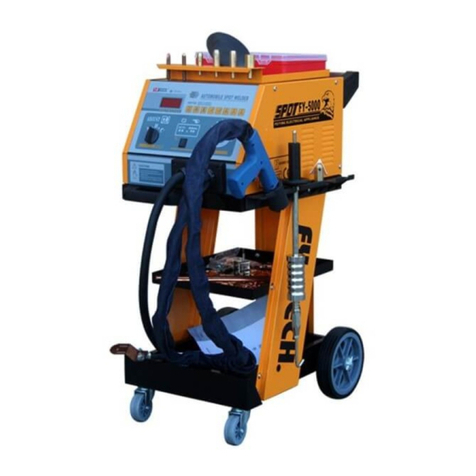
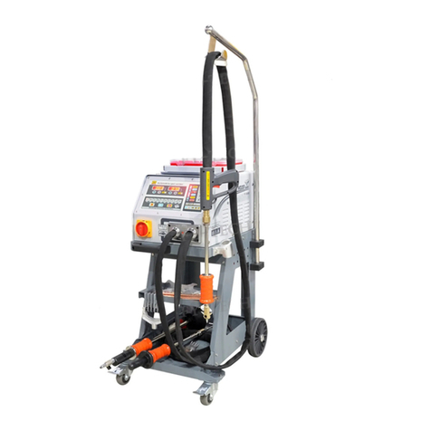
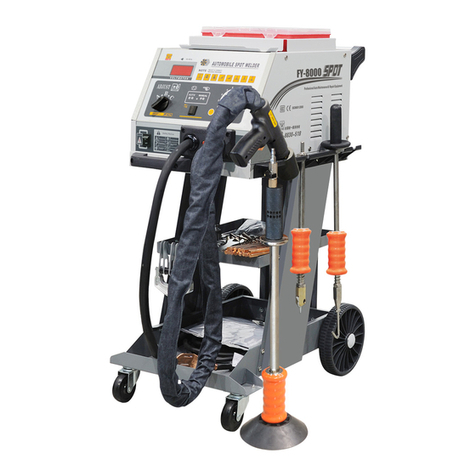
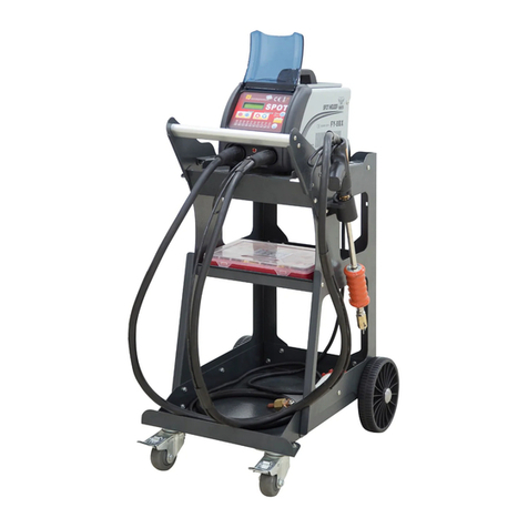
Fytech FY-92G User manual

Owner’s Manual
FY-92G
The equipment is approved by a number of car manufacturers(China)

1、Safety Precautions Symbols
2、Symbols and Definitions
3、Accessories and Spare Parts List
4、Installation
1)、Sp ecifications
2)、D uty Cycle and Overhea ting
3)、Machine Installation
4)、Se lecting a Location
5)、Co nnecting Input Power
5、Operation
1)、Con trols
2)、Welding Gun and Adaptors
3)、Various Oper ations
a、Washer Welding
b、Tr iangle Washer Welding
c、Ca rbon Rod Heating
d、Wave Form Wire Welding
e、Cupules
6、Ma intenance
1、Ex ploded View
2、Tr oubleshooting
7、El ectrical Diagra m
8、Pac king List
1
2
3
4
5
6
7
8
9
10
11
12
13
14
15
16
17
18
Contents

Page.1
Safety Precautions Symbols
Protect yourself and others f rom inj ury,
read and follow these precaut ions be fore
installation and operatio n.
Ex p lod ing p art s c an in jur e .Al w ays w ear a f a ce
sh i eld a nd lo ng sl e eve s。
St ati c ca n d am age P C bo ard s
1、Pu t on gr ou n de d wri st s tra p be f or e
ha ndi ng b o ar ds or p ar ts。
2、Us e pro pe r s ta tic -p roo f ba g s an d box es t o
st ore,move or s hi p P C bo ard s。
1、We ar ap pr o ve d fac e sh iel d or sa fe ty go gg l es
wi th si de s h ie lds。
2、We ar pr op e r bo dy pr ot ect ion t o pr ote ct s k in。
Do n ot we ld i n t he h eig ht!
Read instructions.
1、Read owner's Ma nua l be f or e usi ng o r ser vi c in g
un it。
2、Use only manufacturer’s supplied replacement。
Fl yin g me t al c an in ju re ey es。
1) Wea r sa f et y gla ss es wi th si de s hie ld s o r fa ce
sh iel d。
1、Ma gne ti c f ie lds c an a ffe ct pa ce mak er s .
Pa cem ak e r we are rs k eep a way .
2、We are rs s h ou ld co ns ult t hei r do cto r be f or e
go ing n ea r p la sma a rc c utt in g o pe rat io n s。
Ov e rus e can c aus e o ver hea t in g
Al l ow co oli ng pe r iod , fol l ow r a ted d uty c y cle
before starting to we l d aga in.
El ect ri c s ho ck ca n ki ll:
1、Do n ot to uc h l iv e ele ct ric al p a rt s。
2、We ar dr y, h ol e-f re e ins ul a ti ng gl ov e s an d
bo dy pr ot e ct ion .
3、Do n ot wr ap e l ec tri ca l cab le a r ou nd yo ur
bo dy.
4、Gr oun d th e w or kpi ec e wit h a go o d el ect r-
ic al gr ou n d。
Ey e pro te c ti on fo r we ldi ng :
Cu rre nt l e ve l in am pe rag e Mi n im um sh ad e
Nu mbe r
30-150A---------- --- -- -- - -- -- - -- -- - #8
150-300A--------------------------- # 10
30 0-5 00 A -- ------------------------- #12
Nev e r cut o n p res s uri z ed cyl inde r.
Maintenance regularly!
Fa cto ry s a fe ty!
Fi re or e xp l os ion h az ard .
Do n ot lo ca t e un it on ,o ver ,o r n ea r com bu s ti be
su rfa ce s .D o not i ns tal l un i t ne ar fl am m ab les .
Re mov e al l f la mma bl es of t he w e ld ing a re a .
Fa lli ng u n it c an ca us e inj ur y .
Th e hea t fr o m th e wor kp iec e ca n c au se se ri o us
bu rns。
Fu mes a nd g a se s can b e ha zar dou s
we ldi ng p r od uce s fu mes a nd g a se s. Breathing
th ese f um e s an d gas es c an be h az a rd ous
to y our h ea l th .
If inside,ventilate the area.
Do n ot we ld i n a c on fin ed s pac e onl y if i t
is w ell v en t il ate d.
Pr ote ct y o ur sel f Warn others
Definitions
Symbols and Definitions
U1
U0
U2
I2
s1
HZ
A
V
Rated w e l d i n g
current
Prima r y v o l t a ge
Rated n o l o a d
volta g e ( A a v erage)
Conve n t i o n a l
load vo l t a g e
Power rating,
product o f vo l ta ge
and current(KVA)
Her t z
Amperes
Volts
IP
X
I1max
I1eff
~
1
Rated m a x i m u m
suppl y c u r r e n t
Maximum effective
supply current
Degree of protection
Singl e p h a s e
Duty cycle
Direct current
Constant crrent
Temperature
V
S
I
O
Su ita bl e f or s ome
ha zar do u s lo cat io ns
Volta g e i n p u t
Lo w air p re s su re
li ght
On
Off
Protective earth
(Ground)
Input
+-
%
Adjust air/gas
pressure
Percent
Increase
Line co n n e c t i on
Loose s h i e l d c u p
Autom a t i c
Manua l
Page.2
Do n ot do t hi s

Accessories And Spare parts
Accessories and Spare Parts List:
Remark:
1)、Optionnal orders for above accessories and components are
available.
2)、Model and parts number required when ordering parts from
your local distributor.
Page.3
Waveform electrode tip
NO.F010
NO.F013
Control transformer
NO.F025
Pn eu m at ic v acu um c upu le
NO .F 0 01
Claw puller
NO.F004
Carbon Cod
NO.F007
St ud
NO.F016
Ma nua l cu p ul e
NO.F019
Back wheel
NO.F022
Spot welding electrode
tip NO.F008
Washer adaptor
NO .F0 11
Fr ont p ar t o f pu lle r
NO.F014
Washer
NO.F017
Welding gun
NO.F020
Pull hammer
NO.F002
Ho ok
NO.F005
Vertical spot welding
pull hammer NO.F003
Wriggle
NO.F006
Carbon rod adaptor
NO.F009
Electrode holder
NO.F012
Triangle wasler
NO.F015
Ground wire clamp
NO.F018
Front wheel
NO.F021
Circuit board
NO.F028
Trianger washer adaptor

10KW
0-9 9 ms
0.8+1.2(mm)
180kg
1、specifications
Output voltage
Input power
Input curr ent
Operation way
Time regu lati on sys tem
Operation place
Vacuum cupu le device
Dimension
Instant max.current
One side welding thickness
Weight
Installation
Input voltage
Page.4
Triangle washer welding
Washer welding
Stud welding
Sheet metal flattening
Carbon rod heating
Ima ge Description Time(s) P ow er co ns u mp tio n
(K VA)
welding thickness
Waveform wire welding
0.9-1.5
1.0-2.0
0.5-0.7
0.5-0.7
0.99
0.4-0.8
FFF
FFF
FFF
FFF
FFF
0.7-0.9
0.6-1.2
0.6-1.2
0.6-1.2
0.6-1.2
0.6-1.2
0.6-1.2
220 V 5 0/6 0 Hz
Ste p les s
620*450*980(mm)
540 0 A
55A
Con t inu i ty
80k g
AC1V-10V Carb on rod h eati ng AC6 V -12 V W ash e r fus i on AC1 V-13 V Butt w eld

2、Duty Cycle and Overheating
Duty cycle is percentage of 10 minutes that unit can weld at
rated load without overheating.
If unit overheat,output stops ,and cooling fan runs .Wait fif-
teen minutes for unit to cool.Reduce amperage or duty cycle be-
fore welding.
Page.5
Overheating Sto p w ork i ng Wai t f ift e en mi n ute s
for u n it to c o ol
Red u ce am p era g e or
reduce duty cycle
Wel d again
0
15
A

3、Machine Installation
1)Open the package and find out the owner's manual。
2)Check the supplied of accessories according to packing list
that attached to this manual.
3)Properly install this equipment as following diagram.Inspect
the unit for any problems.If so,contact your local distributor
or service agency.To locate a distributor or service agency.
Page.6

Page.7
4、Selecting a Location
1)Select a correct location to place the unit.
2)Determine input power cord length according to its actual
operation requirement .Make sure that the supply cable is at
2
least 6mm in diameter
3)Do not move or operate unit where it could tip.
4)Use cart or unit handle to move unit .Do not pull the cords
to move unit.

5、Connecting Input Power
2
1、Inp u t pow e r cor d(n ot le s s than 6 mm
cop p er co r d).
2、Ove r -cu r ren t p rot e ctio n.
3、Dis c onn e ct de v ice l i ne ter mina ls.
4、Gro u nd wi r e L1/ L 2 inp u t cond ucto rs.
Ins t all a tio n m ust m e et all N atio nal an d
Local Codes---hav e only q uali fied p e rso n s
mak e t his i n sta l lat i on.
Dis c onn e ct an d l ock o ut/t agou nt inp ut pow er
bef o re co n nec t ing i n put co nduc tors f rom
unit.
Sel e ct ty p e and s i ze of o v er-c urre nt
protection.
Clo s e and s e cur e d oor o n d isco nnec t devi ce .
Remove lockout/tagout device,and place
swi t ch in t h e "on" position.
4
Page.8
3
2
L1
L2
1
1
The power s u p p ly must have a ground conne c t i on.
The welde r m u s t also be connected to circ u i t b reaker.
Th e po wer sup pl y mu st have a g ro un d conne ct ion.
Th e we lder mu st a ls o be conn ec te d to circ ui t breaker .
Power c o n n e c t ion and install a t i o n m u s t meet all
Natio n a l a n d L o cal standards ( C i r c u i t breaker
must be i n s t a l l ed).Only qual i f i e d p e r sons are
allow e d t o m a k e t his installat i o n .
The machine must be grounded(earthed)
properly to prevent accidental
electrical shock.
If you need to open the machine
case(after work every day,make sure to
turn off the external power source and
turn off the power switch on the
machine.

Operation
Page.9
1、Controls
1.
2.
4.
5.
6.
7.
8.
9.
10
LCD Screen
Weld Power-- Down
Weld Power --Up
Weld Time---Down
Weld Time--Up
Weld Program Selection
Overheat Indicator
Manual Weld
Automatic Weld
.Manual/Automatic Selection
11.Earth Cable Output
12.Weld Gun Cable Output
13.Gun Cable Trigger
14.Gun Cable Socket
3.
1
3
10
4
6
8
9
7
5
2
REMARK:
The programs G,H,I,J cannot be used in Automatic Weld.
Weld Time cannot be set to FF(Full).In Automatic Weld,
welding automatically without triggering.
-Pressing the two buttons “Weld Time—Up” and “Weld
Program Selection” at the same to resume to default setting.
- P res s i ng the two but t ons “Weld P ow e r – U p ” a nd
“Manual/Automatic Selection” at the same time for switching
English and Chinese
Weld Program Selection:
Press quickly:Moving icon to the right
Press and hold:Moving icon to the left
11 12
14
13

Page.10
2、Welding Gun and Adaptors
1
Single-Sided applications
5、Tighten up the holder
4、Installed the
fixed shank
2、Put negative wire
into the welded washers
1、 Weld 2 washers
on metal
workpiece ,as close to
welding area as possible.
3、Located the holder
on the welded washers
1、Electrode holder
Car b o Rod S h rin k ing
OT Wa s her W e ldi n g
Was h er We l din g
Stud Welding
Sin g le- s ide d W eld i ng
Wav e f orm W i re We l din g
Pul l ing S p ot Ha m mer
Connection of negative wire
2、Trigger

Page.11
Con n ect w a she r a dap t or with
wel d ing g u n and t i ght e n,
Install washer.
Remark:
1、Set t ing a m per a ge to o h igh or t ime to o long c an cau se wor kpie ce sur f ace ( v ehi c le body)damage .
Ple a se we l d oth e r wor k piec es for p ract ice be fore a ctua l oper a tio n s.
2、Set t ing c o rre c t amp e rage a nd tim e acco rdin g to the w orkp iece t h ick n ess .
3、Con t inu i ng an o the r o pera tion i s avai labl e afte r this p roce d ure f i nis h ed .i f n ot, pl ease
shu t o ff th e m ain p o wer s u pply a nd swi tch of f the un it.
F017+F011+F020
a、Washer Welding
Set c o rre c t tim e .
Set c o rre c t amp e rag e .
App r oxi m ate l y a 90° a ngle t o the
dent.Put o n p res s ure a n d
pre s s tri g ger .
3、Operation
%
Connect negative outside wire
to a clean,paint-free location
on metal workpiece,as close to
welding area as possible.
Rem o ve we l din g g un.H o ok the
was h er wi t h pul l h amm e r.Slide
the h a mme r t o opp o sit e dire ctio n
to pu l l out t h e den t .

Page.12
Con n ect t r ian g el wa s her
pul l h amm e r wit h w eld i ng gun .
App r oxi m ate l y a 90° a n gle to
the d e nt, p ut on p r ess u re
and p r ess t r igg e r.
Sli d e the h a mme r t o opp o site
direction to pul l the de nt out .
F003+F020
b、Triangle Washer Welding
Set c o rre c t tim e .
Set c o rre c t amp e rag e .
3、Operation
Remark:
1、Set t ing a m per a ge to o h igh or t ime to o long c an cau se wor kpie ce sur f ace ( v ehi c le body)damage .
Ple a se we l d oth e r wor k piec es for p ract ice be fore a ctua l oper a tio n s.
2、Set t ing c o rre c t amp e rage a nd tim e acco rdin g to the w orkp iece t h ick n ess
3.Tri a ngl e washer welding can r e pla c e washer welding.It can pull out the dent directly
aft e r wel d ed.
4、Con t inu i ng an o the r o pera tion i s avai labl e afte r this p roce d ure f i nis h ed .I f n ot, pl ease
shu t o ff th e m ain p o wer s u pply a nd swi tch of f the un it.
%
Connect negative outside wire
to a clean,paint-free location
on metal workpiece,as close to
welding area as possible.

Page.13
Con n ect c a rbo n r od an d
carbon rod ad apto r with
welding gun.
Carbon rod turning in
clockwise to heat up
the stretched panel
Use c o ld wa t er or w e t rag
to co o l dow n t he he a ted a r ea
tha t m ake s t he st r etc h ed pan el
shrunken as normal status.
F00 7 +F0 0 9+F 0 20
c、Carbon rod Heating
3、Operation
Set c o rre c t amp e rag e .
Set c o rre c t tim e .
Remark:
1、Set t ing a m per a ge to o h igh or t ime to o long c an cau se wor kpie ce sur f ace ( v ehi c le body)damage .
Ple a se we l d oth e r wor k piec es for p ract ice be fore a ctua l oper a tio n s.
2、Set t ing c o rre c t amp e rage a nd tim e acco rdin g to the w orkp iece t h ick n ess .
3、Con t inu i ng an o the r o pera tion i s avai labl e afte r this p roce d ure f i nis h ed .I f n ot, pl ease
shu t o ff th e m ain p o wer s u pply a nd swi tch of f the un it..
%
Connect negative outside wire
to a clean,paint-free location
on metal workpiece,as close to
welding area as possible.

Page.14
Con n ect w r igg l e wir e electrode
tip w i th we l din g g un.
F006+F010+020
d、
3、Operation
Set c o rre c t amp e rag e .
Se t co rr ect time.
Remark:
1、Set t ing a m per a ge to o h igh or t ime to o long c an cau se wor kpie ce sur f ace ( v ehi c le bo d y)da mage .
Ple a se we l d oth e r wor k piec es for p ract ice be fore a ctua l oper a tio n s.
2、Set t ing c o rre c t amp e rage a nd tim e acco rdin g to the w orkp iece t h ick n ess .
3、Con t inu i ng an o the r o pera tion i s avai labl e afte r this p roce d ure f i nis h ed .I f n ot ,pl ease
shu t o ff th e m ain p o wer s u pply a nd swi tch of f the un it.
Wriggle Form Wire Welding
%
Connect negative outside wire
to a clean,paint-free location
on metal workpiece,as close to
welding area as possible.
Connect hook puller with pull hammer.
Hook wave form wire and slide the
hammer to pull out the dent.
Place a wave form wire horizontally
on the dent.Approximately a 90°angle
to wave form wire.Put on pressure and
press trigger.

3、Operation
Page.15
e、Cupules
Manual operating cupule:
1、Connect manual cupule with
pull hammer.
2、Push manual cupule in to lock
the cupule on the dent.
3、Slide the hammer to opposite direction
to pull the dent out.
Pneumatic vacuum cupule:
1、Connect gas/air supply with the adaptor
of cupule.
2、Open the valve ,sticking cupule to the
dent.
3、Slide the hammer to opposite direction
pull the dent out.
4、Cupule falls off when close the valve.

Maintenance
Page.16
1. Exploded view
Cir c uit b o ard
Control transformer
Control silicon
Main transformer
Lef t s ide v i ew
Control transformer
Control silicon
Mai n t ran s for m er
Cir c uit b o ard
Right side view

2、Troubleshooting
Maintenance
Page.17
Reason Remedy
No welding output
(1)Conne c t e d p o w er supply
incorrectly.
(2)Power s w i t c h i n o ff
posit i o n
(1)Connect power supply according
to manufacturer’s instructions.
(2)Place power switch in “on”
position.
Trigger not working
(1)Trigger damage d .
(2)Gu n c ontrol wire brok e n .
(3)Co n trol wire plug loo s e n .
(4)Mode sw i t c h i n i n correct
position.
(1)Replace trigger.
(2)Co n n e c t a gain or replace i f n e c -
essar y .
(3)Co n n e ct control wire p l u g a g a i n.
(4)Place Mod e s witc h i n c o r r e c t pos-
ition .
(1)Aamperage too low
(2)Weld time too short.
(3)Input power cord did not
meet the requirement.
(4)Ground clamp bad contact.
(1)In c r e a s e a mperage settin g
(2)In c r e a s e t ime setting.
(3)Re p l a c e i n put power cord.
(4)Cha n g e g r o u nd clamp locatio n .
Piercing workpiece
(1)output a m p e r a g e too high.
(2)Weld tim e t o o l o n g .
(3)Bad cont a c t o f e l e ctrode tip or
washe r w i t h w o r kpiece.
(1)Red u c e a m p e rage setting.
(2)Rr d u c e w e l d time.
(3)Re m o v e c o a ting from materi a l
reduc e a d d e d p r essure.
Carbon rod working
unstable
(1)Car b o n r o d o r w orkpiece is dirt y
(2)Incorr e c t a m p e rage and time
setti n g .
(1)Polish carbon rod and workpieces
(2)Set amperage and time according to
workpiece thickness.
Unit stop working
while operation
(1)Tr i g g e r p l ug loosen.
(2)Gu n c o n t r o l wire broken.
(3)Ov e r h e a t i ng.
(1)Check gun c o ntrol wire and
trigg e r p l u g .
(2)Wait fo r t e m p e r ature cool down.
Trouble
Poor weld
.
.
Table of contents
Other Fytech Welding System manuals

Fytech
Fytech FY-4200/2E User manual

Fytech
Fytech FY-4180/2E User manual

Fytech
Fytech FYMIG200L-2 User manual

Fytech
Fytech FYMIG5215X User manual

Fytech
Fytech FY-4250/2E User manual

Fytech
Fytech FY-91G User manual

Fytech
Fytech FY-2012S User manual

Fytech
Fytech FY-5015L User manual

Fytech
Fytech FY-9000 User manual

Fytech
Fytech FY-2270/2E User manual

Fytech
Fytech FY-4280/2E User manual

Fytech
Fytech FYMIG5260 User manual

Fytech
Fytech FYMIG180 User manual

Fytech
Fytech FY-4500 User manual

Fytech
Fytech FY-8L User manual

Fytech
Fytech FYMIG230L User manual

Fytech
Fytech FYMIG300 User manual

Fytech
Fytech FYMIG306L User manual

Fytech
Fytech FYMIG210X User manual

Fytech
Fytech FY-5500/2E User manual