Fytech FY-5015L User manual

Owner’s Manual
The equipment is approved by following car manufacturers(China)
FY-5015L

Contents
1. S afe ty Precaution Symbols
2. S ymb ols & Definitions
3. O pti onal Accessories & Spar e Par ts
4. I nst allation
1) spe cifications
2) D uty C ycle & Overheating
3) M ach ine Installation
4) S ele cting a location
5) C onn ecting Input Power
5. O per ation
1) Aluminium Dent Puller Controls
2) Steel Dent Pulle r Contr ols
3) Aluminium Welding Gun Application
4) Steel Welding Gu n Appli cation
5) Pulling Hammer Application
6) Glue Pulling Kit A pplic ation
7) Steel Dent Pulle r Appli cation
8) Cupules Application
6. Maintenance
7. Circuit Diagra m
..................................1
......................................2
..........................3
..........................................4
................................5
...................................6
....................................7
..................................8
..............................9
.. ... ................. ... .......10
.........................11
.............................12
...............................13
.............................14
.............................15
.....................................19
...............................................20
............................................21

Page.1
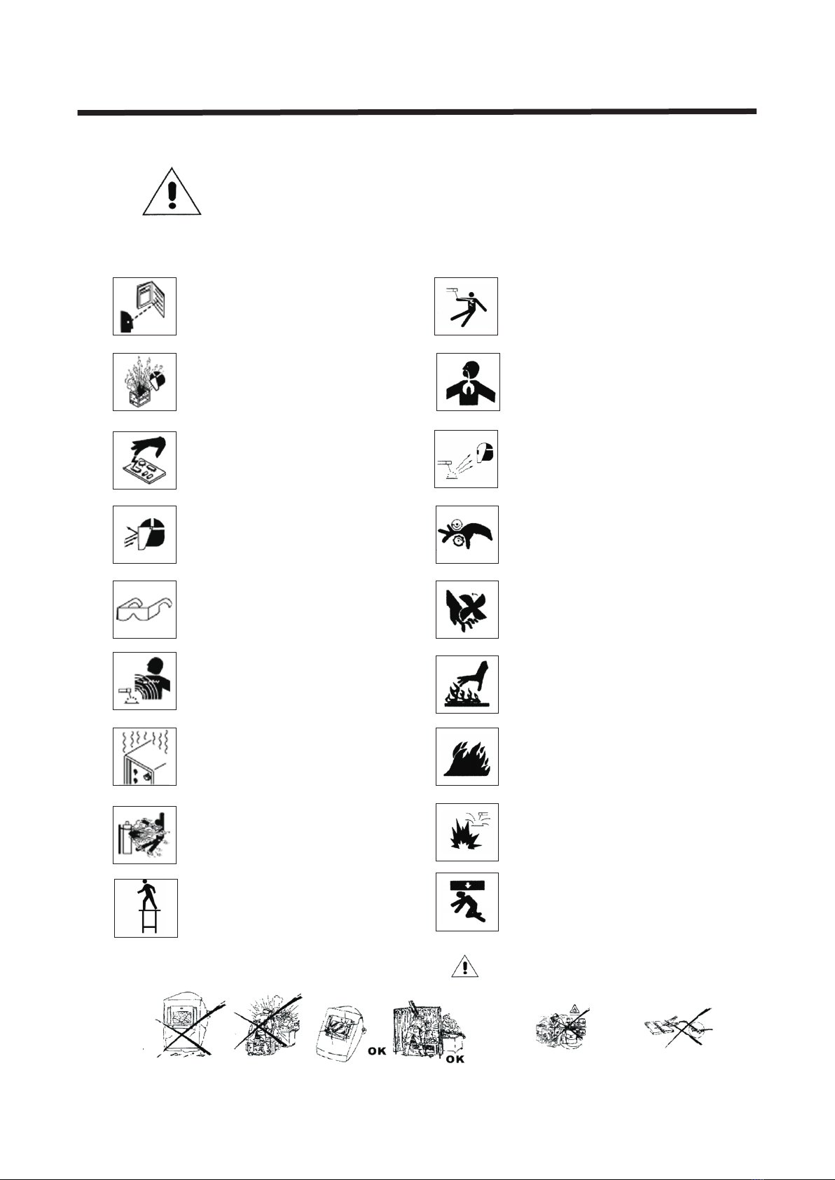
Pro tect you rself and others from injury,
rea d and foll ow these p recautions before
ins tallat ion and operation.
Exploding p a r t s c a n i n j u re.Always wear a face
shield and lo n g s l e e v e s。
Static can damage PC boards
1、Put on grounded wrist strap before
ha n d i n g b o a r d s o r p a rts。
2、Us e p r o p e r s t a t i c - proof bags and bo x e s t o
st o r e,move or s h i p P C b o a r d s。
1、We a r a p p r o v e d f a c e s h ield or safety go g g l e s
wi t h s i d e s h i e l d s。
2、We a r p r o p e r b o d y p r o t ection to prote c t s k i n。
Pa y a t t e n t i o n n o t t o b e crushed by the wh e e l o f
th e w i r e f e e d e r w h e n i nstalling wel d i n g w i r e s
an d c l e a n i n g t h e i n s ide of the machin e .
Pa y a t t e n t i o n n o t t o b e scratched by th e f a n
wh e n i n s t a l l i n g w e l ding wires and cl e a n i n g t h e
in s i d e o f t h e m a c h i n e.
Do n o t w e l d i n t h e h e i g h t!
Read instructions.
1、Read owner's M a n u al before using o r s e r v i c i n g
un i t。
2、Use only manufacturer’s supplied replacement。
Fl y i n g m e t a l c a n i n j u re eyes。
1) W e a r s a f e t y g l a s s es with side shie l d s o r f a c e
sh i e l d。
1、Ma g n e t i c f i e l d s c a n a ffect pacemak e r s .
Pa c e m a k e r w e a r e r s k eep away.
2、We a r e r s s h o u l d c o n s ult their docto r b e f o r e
go i n g n e a r p l a s m a a r c cutting opera t i o n s。
Overuse can c a u s e o v e r h e atin g
Allow cooli n g p e r i o d , f o llow r a t e d d u t y c y c le
before starting t o w e l d a g a i n.
Check the int e g r i t y o f t h e g as cyl i n d e r b e f o r e
use. Any dama g e i n t h e g a s c y l inde r c o u l d c a u s e
explosions.
El e c t r i c s h o c k c a n k ill:
1、Do n o t t o u c h l i v e e l e c trical parts。
2、We a r d r y , h o l e - f r ee insulating gl o v e s a n d
bo d y p r o t e c t i o n .
3、Do n o t w r a p e l e c t r i c al cable around y o u r
bo d y .
4、Gr o u n d t h e w o r k p i e ce with a good elec t r -
ic a l g r o u n d。
Ey e p r o t e c t i o n f o r w elding:
Cu r r e n t l e v e l i n a m p erage Minimum s h a d e
Nu m b e r
30-150A---------- - -- - -- - - -- - -- - --- - # 8
150-300A--------------------------- #1 0
30 0 - 5 0 0 A - - - - ----------------------- #12
Pr e v e n t f i r e o r e x p l osion hazard.
Do n o t l o c a t e u n i t o n , o ver or near combu s t i b l e
su r f a c e s . D o n o t i n s tall unit near fl a m m a b l e s .
Re m o v e a l l f l a m m a b les away from the w e l d i n g a r e a .
Fa l l i n g u n i t c a n c a u se injury.
Th e h e a t f r o m t h e w o r k piece can cause s e r i o u s
bu r n s .
Fu m e s a n d g a s e s c a n b e h azardous
we l d i n g p r o d u c e s f umes and gases. Breathing
th e s e f u m e s a n d g a s e s can be hazardous
to y o u r h e a l t h .
If inside,ventilate the area.
Do n o t w e l d i n a c o n f i n e d space only if it
is w e l l v e n t i l a t e d .
Maintenance regularly!
Fa c t o r y s a f e t y!
Pr o t e c t y o u r s e l f Warn others
Ne ver cut o n pr essur iz ed cyli nd er.
Safety Precaution Symbols

Definitions
U1
U0
U2
I2
s1
HZ
A
V
Rat ed w el di n g
current
Pri ma ry v ol t ag e
Rat ed n o lo ad
vol ta ge (A a ve ra ge )
Con ve nt io n al
loa d vo lt ag e
Power rating,
product of voltage
and current(KVA)
He rtz
Amperes
Volts
IP
X
I1max
I1eff
~
1
Rat ed m ax im u m
sup pl y cu rr e nt
Maximum effective
supply current
De g r e e o f p r o t e c t i on
Sin gl e ph as e
Duty cycle
Direct current
Constant current
Temperature
V
S
I
O
Su i t a b l e f o r s o m e
ha z a r d o u s l o c a t i o ns
Vol ta ge i np u t
Low air pressure
li g h t
On
Off
Protective earth
(Ground)
Input
Power
+-
%
Adjust air/gas
pressure
Percent
Increase
Lin e co nn ec t io n
Loo se s hi el d c up
Aut om at ic
Man ua l
Page.2
Do not d o this
Symbols & Definitions

Accessories and Spare Parts List:
Remark:
1)、Optionnal orde rs for above access ories and compone nts are
available.
2)、Model and parts nu mber required whe n order ing parts fr om
your local distri butor.
Page.3
Φ5mm pulling screw
Φ5 m m s t u d hook
Φ5mm aluminium stud Φ4mm aluminium stud
Φ5mm pulling ring Φ4 m m p u l l i n g r i n g
Φ5mm stud adapter
Φ4mm pulling screw
Φ4 m m s t u d adapter
Φ4 m m s t u d hook
Aluminium two-stand
crossbar lifter
Aluminium four-stand
crossbar lifter
Tools
Φ1 2 m m w a s h e r
To o l b o x
Polisher
10 A f u s e
Waveform electrode tip
NO.F010
NO . F 0 1 3
Control transformer
NO . F 0 2 5
Pneumatic vacuum cupule
NO.F001
Claw puller
NO.F004
Carbon Cod
NO.F007
St u d
NO.F016
Manual cupule
NO.F019
Sp o t w e l d i n g e l e c t r ode
tip NO.F008
Washer adaptor
NO . F 0 1 1
Fr o n t p a r t o f p u l l e r
NO.F014
Washer
NO.F017
Welding gun
NO.F020
Pull hammer
NO.F002
Ho o k
NO.F005
Vertical spot welding
pull hammer NO.F003
Wriggle
NO.F006
Ca r b o n r o d a d a p t o r
NO.F009
El e c t r o d e h o l d e r
NO.F012
Tr i a n g l e w a s l e r
NO.F015
Gr o u n d w i r e c l a m p
NO.F018
Ci r c u i t b o a r d
NO.F028
Trianger washer adaptor
Optional Accessories & Spare Parts

Page.4
1、specifications
Model
Input voltage
Phases
Frequency
Input current
Output current
Fuse
Insulation grade
Capacitance
Charging voltage
Stud diameter
Duty cycle
Model
Input voltage
Phases
Frequency
Output voltage
Input power
Max instantaneous current
Input current
Operation way
Time regulation system
One side welding thickness
AC 220V
Single phase
50/60Hz
2.0A
4A
H grade
66000 UF
50-150V
Ф3-Ф6mm
80%
Alu Dent Puller
600A
Steel Dent Puller
1-13V
18KVA
2200A
54A/18A
Electronic timer
continuously
0-99s
0.8+1.2
Single phase
AC 220V
50/60Hz
Installation

Duty cycle is perce ntage of 10 minutes t hat uni t can weld at
rated load withou t overheating.
If unit overheat, output stops ,and c ooling fan runs .Wait fif-
teen minutes f or unit t o cool.Red uce amp erage or dut y cycle b e-
fore welding.
Page.5
Overheating St op work in g Wa it fift ee n minut es
fo r unit to c oo l
Re duce am pe rage or
reduce duty cycle
Weld ag ain
0
15
A
2. Duty Cycle & Overheating

1)Open the packag e and fin d out the owne r's manu al。
2)Check the suppl ied acc essories a ccord ing to packi ng list
that attached to this manua l.
3)Properly inst all thi s equipmen t as foll owing diag ram.Inspect
the unit for any prob lems.If so,conta ct your l ocal distr ibuto r
or service agency .To loc ate a distri butor o r service ag ency.
Page.6
3. Machine Installation

Page.7
1)Select a correc t locat ion to place t he unit .
2)Determine inp ut powe r cord lengt h accor ding to its ac tual
operation requi remen t .Make sure t hat the s upply cabl e is at
2
least 6mm in diameter
3)Do not move or oper ate uni t where it cou ld tip.
4)Use cart or unit ha ndle to m ove unit .Do no t pull th e cords
to move unit.
4. Selecting a location

2
1、In put pow er c ord(not l es s than 6m m
co pper co rd).
2、Ov er-cu rr ent pro te ction .
3、Di sconn ec t devic e li ne term in als.
4、Gr ound wi re L 1/L2 in pu t condu ct ors.
In stall at ion mus t me et all Na ti onal an d
Local Codes---h av e only qu alified p erson s
ma ke this i ns talla ti on.
Di sconn ec t and loc ko ut/ta go unt inp ut p ower
be fore co nn ectin g in put con du ctors f ro m
unit.
Se lect ty pe a nd size o f ov er-cu rr ent
protection.
Cl ose and s ec ure doo r on d iscon ne ct devi ce .
Remove lockout/tagout device,and place
sw itch in t he "o n" position.
Page.8
4
3
1
2
L1
L2
1
5. Connecting Input Power

1. Aluminium Dent Puller Controls
Page.9
The diameter of studs is 3mm-6mm. The welder is based on stud welding
technology. It has advantages as high efficiency, low heat emission for workpiece
surface, quality weld appearance, firm welded joint and low energy consumption.
It could save your time and materials with excellent weld quality (great strength,
no distortion, no leakage),easy and simple operation without complicated
procedures such as drilling holes, riveting, welding and polishing…etc.The
resistance heat is extensively used in welding field, suitable for welding of
various metallic materials such as magnetism copper, stainless steel, copper,
aluminum, aluminum alloy, etc.
Please read this instruction manual before use .
It is easy and simple to operate the stud welder even though you have no relevant
experience. Firstly, you could turn the main power switch to the “on” position
and adjust the current according to relevant stud diameters. Put the chosen stud
into the gun, then the welding process could be started. The greases of the
workpiece surface should be cleared every time before welding to avoid poor
contact. It has a little welding spatter, please wear glasses and gloves.
You could get the best result by connecting H1 and H2 with both edges of the
workpiece surface for large area welding (you could choose either H1 or H2 for
small area welding).
Weld metallic stud or post form components in sheet metal.
A. Voltage display
B. Voltage indicator
C. Voltage selector
D. Power indicator
E. Overheat indicator
F. Gun trigger indicator
G. Over-voltage indicator
H1/H2. Earth cable
J/K. Gun cable
A
B
D
C
E
F
G
H1H2 J K
Operation

Page.10
2. Steel Dent Puller Controls
Operation
1
2
3
4
5
6
78
9
10
1. LCD display
2. Current decrease
3. Current increase
4. Time decrease
5. Time increase
6. Function selection
7. Earth cable
8. Gun cable
9. Gun testing button
10. Trigger control cable

1
2
%
3
Wrong
Right
(1) (2)
A. Aluminium welding gun
1、 Ferrule
2、 Trigger switch
3、Weld chuck
B. Aluminium welding gun setup
1.Insert a ferrule grip into the foot and tighten the frerule
2.Insert a stud into the weld chuck.A different chuck is required for each different stud
diameter(0.6mm chuck with 0.6mm stud,0.4mmchuck with 0.4mm stud)
3.Place the weld chuck into the chuck adapter.Make sure that the chuck is seated
properly in the adapter.
C. Aluminium welding gun application
Connect ground cable to
a clean,paintfree location
on metal workpiece,as
close to welding area as
possible.
Weld gun with
chuck and stud
Adjust current
(See page 9)
Place the weld gun perpendicular
to the dent area on the workpiece.
Apply pressure to the gun.Hold
gun steady and push trigger to
weld..
Remark:
1、Setting amperage too high or time too long can cause workpiece surface (vehicle body)damage .
Please weld other workpieces for practice before actual operations.
2、Setting correct amperage and time according to the workpiece thickness.
3、Continuing another operation is applicable after these procedures finished .If not, please
shut off the main power supply and switch off the unit.
Page.11
3. Aluminium Welding Gun Application

Page.12
1
Single-Sided applications
5、Tighten up the holder
4、Installed the
fixed shank
2、Put negative wire
into the welded washers
1、 Weld 2 washers
on metal
workpiece ,as close to
welding area as possible.
3、Located the holder
on the welded washers
1、Electrode holder
Ca rbo Rod S hr inkin g
OT W asher W el ding
Wa sher We ld ing
Stud Welding
Si ngle- si ded Wel di ng
Wa ve form W ir e Weldi ng
Pu lling S po t Hamme r
Connection of negative wire
2、Trigger
4. Steel Welding Gun Application

Remark:
1、Setting amperage too high or time too long can cause workpiece surface (vehicle body)damage .
Please weld other workpieces for practice before actual operations.
2、Setting correct amperage and time according to the workpiece thickness.
3、According to actual conditions to select a suitable puller for repairing
4、The nut of the puller is to adjust the up and down moving range of the main axle
5、Continuing another operation is available after this procedure finished .If not ,please
shut off the main power supply and switch off the unit.
Weld the studs to the dent area of
car body. Put the corresponding
pulling screw on the studs and
tighten up.
Choose crossbar lifter: Make sure the
crossbar lifter with pulling hook is fixed on
the car body. Connect the pulling hook to the
pulling screw. Adjust the adjusting screw of
the crossbar lifter. Squeeze the lever to pull
out the dent.
Choose crossbar lifter: Make sure the
crossbar lifter with pulling hook is fixed on
the car body. Connect the pulling hook to
the pulling screw. Adjust the adjusting
screw of the crossbar lifter. Rotate the
lever to pull out the dent.
Choose pulling hammer: Connect
corresponding pulling hook to the pulling
screw. Slide the hammer to opposite
direction to pull out the dent.
A variety of pulling hooks are available to fit crossbar lifter and pulling hammer.
Page.13
5. Pulling Hammer Application

Tighten the corresponding
pulling ring to the pulling plate.
Insert the glue stick to the
gun. Make sure the glue
stick is seated properly..
Connect power supply to the gun, and
point to the back side of pulling plate.
Push trigger switch (according to
operation, select power 60W or 100W)
to squeeze out the glue to the plate.
After pulling out the dent, use a hot air blow
gun pointing the hot air to pulling plate to
remove the glue from car body.
Clean the pulling plate for next use.
Remark:
1、Setting amperage too high or time too long can cause workpiece surface (vehicle body)damage .
Please weld other workpieces for practice before actual operations.
2、Setting correct amperage and time according to the workpiece thickness.
3、According to actual conditions to select a suitable puller for repairing
4、The nut of the puller is to adjust the up and down moving range of the main axle
5、Continuing another operation is available after this procedure finished .If not ,please
shut off the main power supply and switch off the unit.
Stick the glued pulling plate (the
back side must be full of glue) to
the dent area of car body which
should be polished and cleaned.
Insert a metal rod through the
pulling ring.
Choose crossbar lifter: Make sure the
crossbar lifter with pulling hook is fixed on
the car body. Connect the pulling hook to the
pulling plate. Adjust the adjusting screw of
the crossbar lifter. Squeeze the lever to pull
out the dent.
Choose crossbar lifter: Make sure the
crossbar lifter with pulling hook is fixed on
the car body. Connect the pulling hook to the
pulling plate. Adjust the adjusting screw of
the crossbar lifter. Roate the lever to pull
out the dent.
Choose pulling hammer: Connect
corresponding pulling hook to
the pulling plate. Slide the
hammer to opposite direction to
pull out the dent.
Page.14
6. Glue Pulling Kit Application

Page.15
Co nnect w as her ada pt or with
we lding g un a nd tigh te n,
Install washer.
Remark:
1、Se tting a mp erage t oo h igh or ti me t oo long c an c ause wo rkpiece s urfac e (v ehicl e body)damage .
Pl ease we ld o ther wo rk piece s fo r pract ic e befor e actual op erati on s.
2、Se tting c or rect am pe rage an d ti me acco rd ing to th e workpie ce thic kn ess.
3、Co ntinu in g anoth er o perat io n is avai la ble aft er this pro cedur e fi nishe d .i f not, pl ea se
sh ut off th e ma in powe r su pply an d sw itch of f th e unit.
F017+F011+F020
a、Washer Welding
Se t corre ct t ime.
Se t corre ct a mpera ge .
Ap proxi ma tely a 90 °a ngle to t he
dent.Pu t on pres su re and
pr ess tri gg er.
%
Connect negative outside wire
to a clean,paint-free location
on metal workpiece,as close to
welding area as possible.
Re move we ld ing gun .Ho ok the
wa sher wi th p ull ham me r.Slide
th e hamme r to o pposi te direc ti on
to p ull out t he d ent .
7. Steel Dent Puller Application

Page.16
Co nnect t ri angel w as her
pu ll hamm er w ith wel di ng gun.
Ap proxi ma tely a 90 ° an gle to
th e dent, pu t on pres su re
an d press t ri gger.
Sl ide the h am mer to op po site
direction t o pull th e de nt out.
F003+F020
Se t corre ct t ime.
Se t corre ct a mpera ge .
Remark:
1、Se tting a mp erage t oo h igh or ti me t oo long c an c ause wo rkpiece s urfac e (v ehicl e body)damage .
Pl ease we ld o ther wo rk piece s fo r pract ic e befor e actual op erati on s.
2、Se tting c or rect am pe rage an d ti me acco rd ing to th e workpie ce thic kn ess
3.Tr iangl e washer welding can r eplac e washer welding.It can pull out the dent directly
af ter wel de d.
4、Co ntinu in g anoth er o perat io n is avai la ble aft er this pro cedur e fi nishe d .I f not, pl ea se
sh ut off th e ma in powe r su pply an d sw itch of f th e unit.
%
Connect negative outside wire
to a clean,paint-free location
on metal workpiece,as close to
welding area as possible.
b、Triangle Washer W elding
7. Steel Dent Puller Application

Page.17
Co nnect c ar bon rod a nd
carbon r od adap to r with
welding gun.
Carbon rod turning in
clockwise to heat up
the stretched panel
Us e cold wa te r or wet ra g
to c ool dow n th e heate d ar ea
th at make s th e stret ch ed pane l
shrunken as normal status.
F0 07+F0 09 +F020 Se t corre ct a mpera ge .
Se t corre ct t ime.
Remark:
1、Se tting a mp erage t oo h igh or ti me t oo long c an c ause wo rkpiece s urfac e (v ehicl e body)damage .
Pl ease we ld o ther wo rk piece s fo r pract ic e befor e actual op erati on s.
2、Se tting c or rect am pe rage an d ti me acco rd ing to th e workpie ce thic kn ess.
3、Co ntinu in g anoth er o perat io n is avai la ble aft er this pro cedur e fi nishe d .I f not, pl ea se
sh ut off th e ma in powe r su pply an d sw itch of f th e unit..
%
Connect negative outside wire
to a clean,paint-free location
on metal workpiece,as close to
welding area as possible.
c、Carbon Rod Heatin g
7. Steel Dent Puller Application

Page.18
Co nnect w ri ggle wi re electrode
ti p with we ld ing gun .
F006+F010+020
Se t corre ct a mpera ge .
Set correc t tim e.
Remark:
1、Se tting a mp erage t oo h igh or ti me t oo long c an c ause wo rkpiece s urfac e (v ehicl e bo dy)da ma ge .
Pl ease we ld o ther wo rk piece s fo r pract ic e befor e actual op erati on s.
2、Se tting c or rect am pe rage an d ti me acco rd ing to th e workpie ce thic kn ess.
3、Co ntinu in g anoth er o perat io n is avai la ble aft er this pro cedur e fi nishe d .I f not ,pl ea se
sh ut off th e ma in powe r su pply an d sw itch of f th e unit.
%
Connect negative outside wire
to a clean,paint-free location
on metal workpiece,as close to
welding area as possible.
Connect hook puller with pull hammer.
Hook wave form wire and slide the
hammer to pull out the dent.
Place a wave form wire horizontally
on the dent.Approximately a 90°angle
to wave form wire.Put on pressure and
press trigger.
d、Wriggle Wire Weld ing
7. Steel Dent Puller Application
Table of contents
Other Fytech Welding System manuals

Fytech
Fytech FY-HI-1100W User manual

Fytech
Fytech FY-6G User manual

Fytech
Fytech FY-8000 User manual

Fytech
Fytech FY-9G User manual

Fytech
Fytech FY-4200/2E User manual

Fytech
Fytech FYMIG210X User manual

Fytech
Fytech FY-91G User manual

Fytech
Fytech FY-3180A User manual

Fytech
Fytech FY-9000 User manual

Fytech
Fytech FY-4250/2E User manual

Fytech
Fytech FYMIG300 User manual

Fytech
Fytech FY-7000 User manual

Fytech
Fytech FY-4220/2E User manual

Fytech
Fytech FY-9028 User manual

Fytech
Fytech FYMIG5260 User manual

Fytech
Fytech FYMIG306L User manual

Fytech
Fytech FY-2270/2E User manual

Fytech
Fytech FY-92G User manual

Fytech
Fytech FYMIG230L User manual

Fytech
Fytech FY-4180/2E User manual