G.R.A.S. 45CA User manual

Instruction Manual
Hearing-Protector Test Fixture Type 45CA
Skovlytoften 33, 2840 Holte, Denmark
SOUND & VIBRATION
G R A S
...
.

Revision 28 November 2013
LI0024

G.R.A.S. SOUND & VIBRATION
CONTENTS
1 Introduction . . . . . . . . . . . . . . . . . . . . . . . . . . . . . . . . . . . . . . . . . . . . . . . . . . . . . 4
1.1 Main Features . . . . . . . . . . . . . . . . . . . . . . . . . . . . . . . . . . . . . . . . . . . . . . . . . . . . . 4
1.2 WhichCongurationtoUse ..........................................5
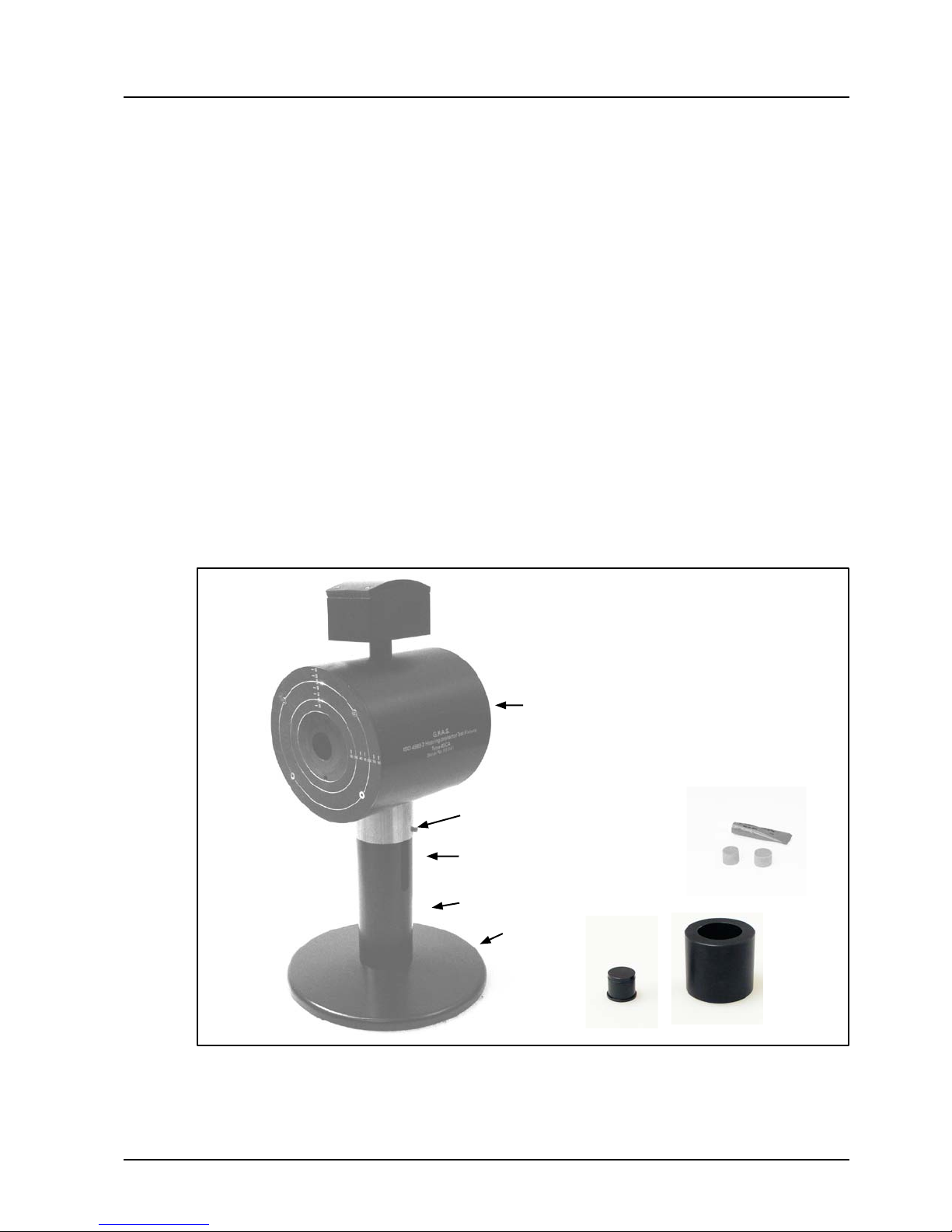
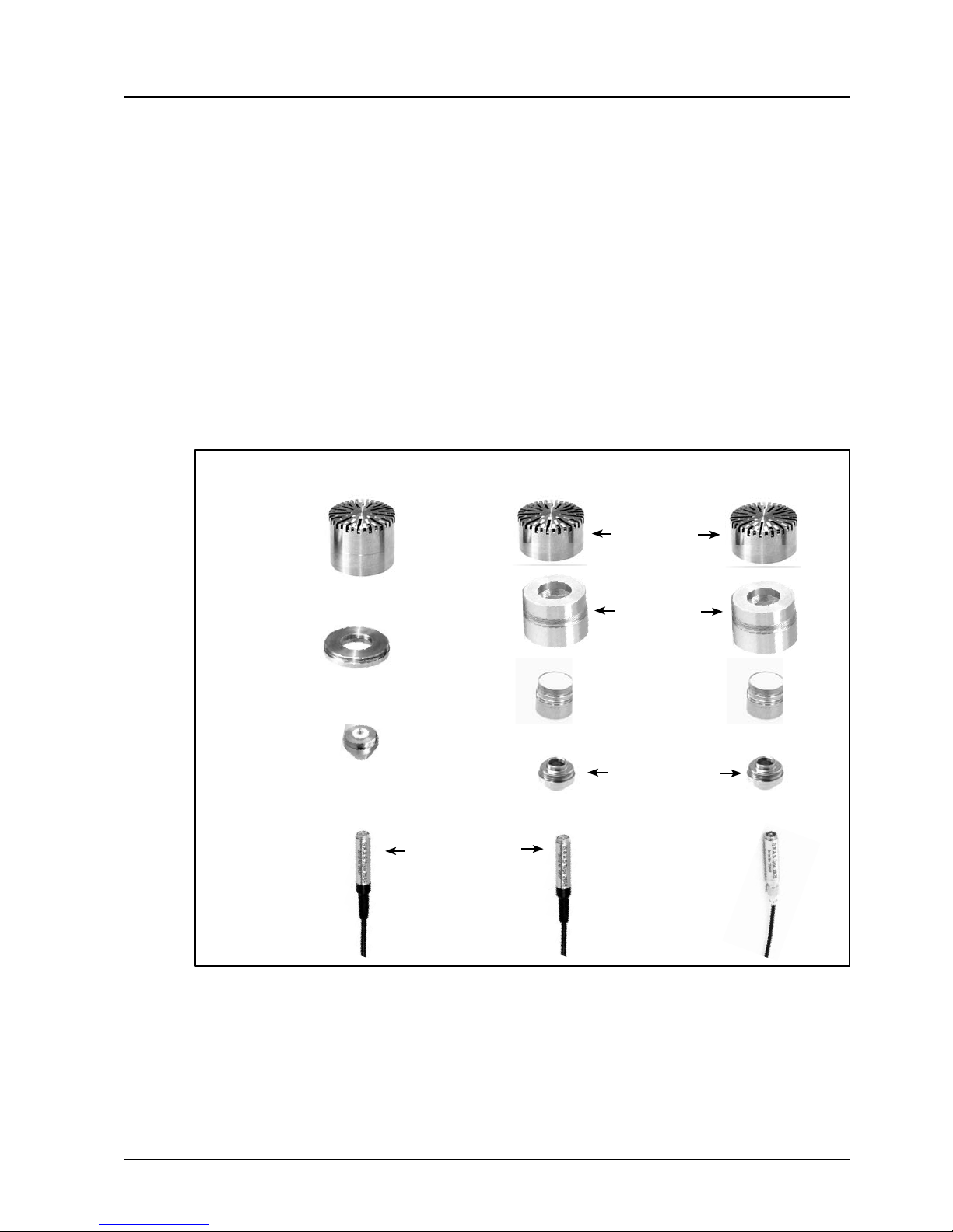
2 Delivered Components............................................6
3 IMPORTANT! Basic Assembly - Safety instructions ....................7
4 CongurationwithPressureMicrophone,
1"Type 40EN or ½"Type 40AP/40AD. . . . . . . . . . . . . . . . . . . . . . . . . . . . . . . . . 8
4.1 AssemblingMicrophoneandPreamplier ...............................8
4.2 Calibration. . . . . . . . . . . . . . . . . . . . . . . . . . . . . . . . . . . . . . . . . . . . . . . . . . . . . . . . 9
4.3 Mounting the Assembly into the Test Fixture ............................10
4.4 Acoustic Isolation Testing ...........................................14
4.5 Typical Application Setup ...........................................15
5 CongurationwithIEC60318EarSimulatorRA0039. . . . . . . . . . . . . . . . . . 16
5.1 EarSimulator/PreamplierAssembly .................................16
5.2 Calibration. . . . . . . . . . . . . . . . . . . . . . . . . . . . . . . . . . . . . . . . . . . . . . . . . . . . . . . 17
5.3 Completing the Assembly . . . . . . . . . . . . . . . . . . . . . . . . . . . . . . . . . . . . . . . . . . . 18
5.4 Mounting Assembly into Test Fixture ..................................19
5.5 Typical Application Setup ...........................................22
6 CongurationwithIEC60711EarSimulatorRA0045orRA0045-S1 . . . . . . 23
6.1 AssemblingEarSimulatorandPreamplier .............................23
6.2 Mounting the Assembly into the Test Fixture ............................24
6.3 Calibrating IEC 60711 Ear Simulator Coupler RA0045.....................27
6.4 Mounting the KEMAR Pinna .........................................28
6.5 Typical Application Setup ...........................................29
7 TechnicalSpecications .........................................30
8 WhattoOrder ..................................................31

G.R.A.S. SOUND & VIBRATION Page 4
Hearing-Protector Test Fixture Type 45CA
Blind Plug
GR1079
Resilient base
Neck
Fig. 1.1 Assembled test xture Type 45CA including Acoustic Plug and Acoustic Cup.
1 Introduction
The G.R.A.S. Hearing-Protector Test Fixture Type 45CA (Fig. 1.1) is for testing
• Hearing protection devices such as ear muffs and earplugs
• Sound sources such as headphones (supra-aural, circum-aural) and earphones.
Thetestxturecanbeusedwithoneofthefollowingmicrophonesorearsimulators:
• 1"or ½"pressure microphones. If used with 1"microphones,thetestcongurationconforms
with ISO 4869-3.
• IEC 60711 (IEC 60318-4) Ear Simulator RA0045.
• IEC 60318 (IEC 60318-1) Ear Simulator RA0039.
1.1 Main Features
The Test Fixture Type 45CA provides for reliable and exact measurements and was designed
withthefollowingfeatures:
• Thetestxture,mountedonaresilientbase(Fig.1.1)thatreducesthenoiseoortoamini-
mum in a typical test situation. Foam plugs and grease (Fig. 1.1) are supplied to avoid sound
leakage along the cable.
• Thetestxturehead,madeforoptimizingtheacousticisolation.
• An acoustic cup and plug for testing the acoustic isolation (Fig. 1.1).
• Arangeofmoulded-rubberKEMARpinnae,e.g.fortestingearplugs,canbetted.
Head
Pedestal (neck + resilient base)
Two 1.5 mm Allen grub screws - must
ALWAYS be tightened when pedestal
and head are assembled
Cup
GR0974
Tube of
Sealing Grease
MI0016
2 x Foam Plug
GR1281

G.R.A.S. SOUND & VIBRATION Page 5
Hearing-Protector Test Fixture Type 45CA
1.2 WhichCongurationtoUse
Table1showswhateachofthethreecongurationscanbeusedfor:
ISO4869-3Congurationwith1"(or½"*)Microphone*
Pressuremicrophones,bothexternallyandpolarizedtypesavailable.
Thecongurationisapplicablefortestingoutside-the-eardevices;i.e.
• For measuring the insertion loss of ear muffs
• For testing the sound quality of earphones
IEC60318CongurationwithEarSimulatorRA0039
RA0039 simulates an ear and is used for measuring the sound pressure at the ear entrance
point (EEP).
RA0039mustbeconguredwitha½"microphone,externallypolarizedorprepolarized.
IEC60711CongurationwithEarSimulatorRA0045
Theseearsimulatorsareforusewithapinnasimulator(articalear)formeasuringthesound
pressure at the eardrum (DRP), thus also applicable for ear inserts. RA0045 available both in
externallypolarizedorprepolarizedversions.
Standard ISO 4869-3 * IEC 60318 IEC 60711
Test Setup
(G.R.A.S.equip-
menttouse)
Pressure Microphone
– 1"40EN or
– ½"40AP/40AD
Ear Simulator RA0039
with ½"microphone:
– 40AG (ext. pol.) or
– 40AO (pre-pol.)
Ear Simulator
– RA0045 (ext. pol.) or
– RA0045-S1 (pre-pol.)
Device to test
Ear muffs
+ + +
Earplugs
- - +
Headphones
+ + +
Earphones
- - +
Hearing-aids
- - +
080016
*ThecongurationwillbeinconformitywithISO4869-3onlyif1"Microphone Type 40EN is used.
Table 1 Providing an overview: Which conguration to use

G.R.A.S. SOUND & VIBRATION Page 6
Hearing-Protector Test Fixture Type 45CA
1 x Acoustic plug
GR1079
1 x Acoustic cup
GR0974
1 x Resilient base
GR0986
1 x Test
xtureneck
Allenkeys:
1 x 6.0 mm YY0019
1 x 2.5 mm YY0016
1 x 2.0 mm YY0018
1 x 1.5 mm YY0012
2 Delivered Components
2 x Cover plate
GR1085
1xTestxturehead
1 x Allen
screw 6 mm
SK1544
Fig. 2.1 Parts delivered in the Type 45CA box.
2 x Insert
GR0970
Tube of
Sealing Grease
MI0016
2 x Foam Plug
GR1281

G.R.A.S. SOUND & VIBRATION Page 7
Hearing-Protector Test Fixture Type 45CA
3 IMPORTANT! Basic Assembly - Safety instructions
Beforeproceedingtooneofthethreecongurationoptionsinsections4,5,or6,dothebasic
assemblyofthetestxtureaccordingtostep1-4:
1. Placethetestxtureneckontoasolidtable,andndthesuppliedscrewand6mmAllenkey
(Fig. 3.1).
2. Place the screw into the bottom of the resilient base, and screw the base onto the neck with
the Allen key (Fig. 3.2).
Fig. 3.1 Fig. 3.2
Testxture
neck
Resilient base
3. After making sure both of the 1.5 mm Allen grub screws in the head’s steel tube are
loosened to their extreme positions, place the head onto the pedestal and carefully slide the
steel tube onto the top of the pedestal’s neck (Fig. 3.3).
4. Tighten both of the 1.5 mm Allen grub screws on the steel tube (Fig. 3.4).
IMPORTANT!
Tighten both of
these 1.5-mm
Allen grub screws
Fig. 3.3 Fig. 3.4
Testxture
head
Pedestal
Steel tube
1.5 mm Allen grub
screws loosened to their
extreme positions
Testxtureneck
Screw
6 mm
SK1544 Allen key
6 mm
YY0019
Allen key
1.5 mm
YY0012
ATTENTION!
When assembling head and pedestal, always make sure to tighten both of the 1.5 mm Allen
grub screws in the steel tube as indicated in Fig. 1.1.
Screw
6 mm
SK1544

1"Pressure
Microphone
Type 40EN
1"to ½"Adapter
RA0017
½"to ¼"
Adapter
RA0003,
NOT Included
with the
¼"Preamplier
Type 26AS
¼"Preamplier,Short
Type 26AS *
1"to ½"
Microphone
Adapter
RA0058
1"Microphone
Protection
Grid
RA0177
½"to ¼"Adapter
GR0010
(included with the
¼"Preamplier)
½"Pressure
Microphone
Type 40AP,
protection
grid removed
½"Pressure
Microphone
Type 40AD,
protection
grid removed
¼"Preamplier,Short
Type 26CS *
Cable AA0018
G.R.A.S. SOUND & VIBRATION Page 8
Hearing-Protector Test Fixture Type 45CA
Fig. 4.1 Assembly options (exploded view)
4 CongurationwithPressureMicrophone,
1"Type 40EN or ½"Type 40AP/40AD
Applications
Insertion Loss of Ear Muffs. If Microphone 1"Type40ENisused,thecongurationisinconform-
ity with ISO 4869-3.
RequiredAccessories
• The parts shown in Fig. 4.1 (choose one of the three assembly options)
• Pistonphone Type 42AP (recommended) or Type 42AA
• Test instruments such as those shown in Fig. 4.14
4.1 AssemblingMicrophoneandPreamplier
Fig.4.1displaysthreeoptionsforthemicrophone/preamplierassemblyrequiredforthemeas-
urements.
1"Type 40EN OR ½"Type 40AP OR ½"Type 40AD
_____________
* For space limitations, the super-short ¼"PreamplierType26AS/Type26CS(shown)isrequiredforbinauralmeasure-
ments. For monaural measurements, replaceType 26AS with Type 26AC and Type 26CS with Type 26CB.

4.2 Calibration
Beforemountingthemicrophone/preamplierassemblyintothetestxture,youmustcalibrate
the assembly using Pistonphone Type 42AP or Type 42AA (with optional 1"coupler adapter)
• Forinstructionsoncalibratingthemicrophone-preamplierassembly,refertothepiston-
phone’s instruction manual.
• The Pistonphone Type 42AP is delivered with an adapter for calibrating 1"microphones.
Fig. 4.2 Assembly of 1"microphone and ¼" preamplier to be calibrated
G.R.A.S. SOUND & VIBRATION Page 9
Hearing-Protector Test Fixture Type 45CA

4.3 MountingtheAssemblyintotheTestFixture
1. SeeFig.4.3:
– Mount the Cover Plate GR1085.
– Mount the Insert GR0970.
(Both items are already mounted at delivery).
G.R.A.S. SOUND & VIBRATION Page 10
Hearing-Protector Test Fixture Type 45CA
Fig. 4.3 Cover plate and insert to be mounted
2.UsingAllenkey1.5mm,loosenthetwo1.5mmgrubscrews(Fig.4.3),andseparate
the head from the pedestal.
Up
Insert
GR0970
Allen grub screws,
1.5 mm
Right
Cover plate
GR1085
Screws,
2.0 mm
Hole for
screw,
1.5 mm

G.R.A.S. SOUND & VIBRATION Page 11
Hearing-Protector Test Fixture Type 45CA
3.Passtheamplier’sLEMOplugendthroughthesideofthehead(g.4.4)untilitdrops
through the tube (Fig. 4.5).
Fig. 4.4 Fig. 4.5
4. Pull the cable through until there is just a manageable amount sticking out of the side of the
head (Fig. 4.6).
5. On top of the neck, slide the cable into the inner slot hole of the rubber pad on top (Fig. 4.7).
Fig. 4.6 Fig. 4.7
6. Push the two Foam Plugs GR1281 into the cable guide right underneath the rubber pad,
one plug on top of the other, while keeping the cable behind the plugs (Fig 4.8).
7. If required for meeting your requirements for acoustic isolation, apply Grease MI0016
to seal leakage points (Fig. 4.9).
Fig. 4.8 Fig. 4.9
2 x Foam Plugs
(GR1281) in their
uppermost positions
Cable in inner
slot hole of the
rubber pad
Apply Grease
MI0016
Cable behind Foam Plugs

G.R.A.S. SOUND & VIBRATION Page 12
Hearing-Protector Test Fixture Type 45CA
8. Replace the head onto the pedestal (Fig. 4.10)
Note: Do not forget to tighten both of the 1.5 mm Allen grub screws.
To Power module
Head
Microphone/preamplier
assembly
Pedestal
Tube
Split hole
Slides on
and off the
pedestal
Fig. 4.10 Cabeling for the microphone-preamplier assembly
Always tighten
both of the
1.5-mm screws

1.89 mm
Insert
GR0970
Grub screws for holding the
microphone in position.
UseAllenkey,2.5mm,YY0016
G.R.A.S. SOUND & VIBRATION Page 13
Hearing-Protector Test Fixture Type 45CA
Fig. 4.11 Correct position of the Microphone Type 40EN relative to the slanting plane of
the head
9.Thelaststepistoensurecorrectmicrophonepositioning:
Figure 4. of ISO 4869-3 shows that the center of the microphone’s diaphragm must be
level in the vertical plane with the slanting surface of the head.
For Microphone Type 40EN, this will be the case when the center of the protection grids
sticks out by 1.89 mm in the vertical plane with the slanting surface of the head.
Usethegrubscrewstopinchthemicrophoneslightly to hold them in position.
Note: If you cannot get the microphone positioned to the correct depth, loosen the four
screws on the face and the single screw on the inlay. Then, gently maneuver the
microphone into place, taking care not to push it completely into the cavity.

G.R.A.S. SOUND & VIBRATION Page 14
Hearing-Protector Test Fixture Type 45CA
4.4 Acoustic Isolation Testing
ISO4869-3section5.1.4speciesaminimumacousticisolationforthetestxture.
Cup GR0974 and Plug GR1079 (Fig. 2.1) are provided to check this.
1.StartwithType45CAttedwithamicrophoneasdescribedintheprevioussection.
2. Remove the Insert GR0970 surrounding the microphone (Fig. 4.12).
3. Push the Cup GR0974 with its hollow facing the microphone into the recess surrounding the
microphone until it makes contact with the base of the recess (Fig. 4.13).
4. Fig.4.14:Ontheopposite side of the Type 45CA, push Plug GR1079 into the hole as far
as it will go. For sound leakage sealing, apply Silicon Grease MI0016 to the plug.
5. Type 45CA is now ready to be tested for acoustic isolation (Fig. 4.15).
Fig. 4.12 Fig. 4.13
Fig. 4.14 Fig. 4.15
Acoustic Cup
GR0974
Vacate
recess
Insert
GR0970
1.5 mm
screw
Push until
cup makes
contact
with base
of recess
Inner edge
Acoustic
Plug
GR1079
Acoustic
Cup
GR1079
Push plug until
its inner edge
makes contact
with base of
recess
Plug
GR1079

4.5 Typical Application Setup
Fig. 4.16 shows a block diagram of an application setup for testing the insertion loss of a pair of
ear-protection muffs.
Fig. 4.16 Block diagram of a setup for testing a pair of ear-protection muffs.
For binaural measurements, you can replace the single-channel Power
Module Type 12AK with the dual-channel Power Module Type 12AA.
Analyzerwithhardwareandsoftware
forsimulating:
a signal generator capable of gen-
erating the required test signals
an audio frequency analyser capa-
bleof⅓-octavebandanalyses
Loudspeaker
Toanalyzer
Poweramplier
Ear muffs under test
Power Module
Type 12AK
From
preamplier
Test Fixture Type 45CA
G.R.A.S.
Power Module
Type 12AK
Gain
+20
+10 +30+40
+50
0
HP Dir
Lin AW
Filter
Overload
Inst. Latch
SysCh.
Adjust
Power
On
Ovl.
Reset
Low
Batt.
SignatureSeries
Output
Input
080012
G.R.A.S.
ISO 4869-3 Hearing-protector Test Fixture
Type 45CA
Serial No. XXXXX
G.R.A.S. SOUND & VIBRATION Page 15
Hearing-Protector Test Fixture Type 45CA
080001

Fig. 5.1 Both assembly options for tests using the IEC 60318 Ear Simulator RA0039
½"to ¼"Adapter
GR0010
(supplied with the
¼"preampliers)
¼"Preamplier
Type 26AC *
Adapter
RA0176
½"Externally
Polarized
Microphone
Type 40AG
5 CongurationwithIEC60318EarSimulatorRA0039
This ear simulator can be used with
• ½"ExternallyPolarizedPressureMicrophoneType40AG
• ½"PrepolarizedPressureMicrophoneType40AO.
Applications
Monaural or binaural measurements of
• Hearingprotectiondevices:Ear muffs (supra-aural, circum-aural)
• Soundsources:Headphones (supra-aural, circum-aural).
Note: As the coupler is not for use with a pinna simulator, it cannot be used for testing
ear-inserts (earphones and earplugs).
RequiredAccessories
• The items of one of the two assembly options shown in Fig. 5.1
• Pistonphone Type 42AP (recommended) or Type 42AA
• Test equipment such as the instruments shown in Fig. 5.15
5.1 EarSimulator/PreamplierAssembly
Fig.5.1displaysthetwooptionsforcongurationwithEarSimulatorRA0039.
Note: Do not assemble the parts yet - proceed to Section 5.2 Calibration.
ExternallyPolarizedMicrophone PrepolarizedMicrophone
¼"CCP
Preamplier
Type 26CB *
½"Prepolarized
Microphone
Type 40AO
IEC 60318
Ear Simulator
RA0039
_____________
* For space limitations, ¼"PreamplierType26AC/Type26CB(shown)canbeusedformonauralmeasurementsonly.
For binaural measurements, replace Type 26AC with Type 26AS and Type 26CB with Type 26CS.
G.R.A.S. SOUND & VIBRATION Page 16
Hearing-Protector Test Fixture Type 45CA

5.2 Calibration
Tocalibratethisconguration,usePistonphoneType42APorType42AA.Bothofthemare
deliveredwithanadapterforcalibrating½″microphones.
1.Assemble the parts shown in Fig. 5.2
ExternallyPolarizedMicrophone PrepolarizedMicrophone
2. Perform the calibration.
Forinstructionsoncalibratingthemicrophone-preamplierassembly(Fig.5.3),seethe
Pistonphone Type 42AP or Type 42AA instruction manual.
Fig. 5.3 ½″ microphone and ¼″ preamplier to be calibrated
½″to¼″Adapter
GR0010
(included with the
¼″preampliers)
½″Externally
Polarized
Microphone
Type 40AG
¼″CCP
Preamplier
Type 26CB
½″Prepolarized
Microphone
Type 40AO
Fig. 5.2 Assembling the parts required for the calibration
Cable AA0018
¼″Preamplier
Type 26AC
G.R.A.S. SOUND & VIBRATION Page 17
Hearing-Protector Test Fixture Type 45CA

5.3 CompletingtheAssembly
1. Unscrewthemicrophone
Fig. 5.4
2. Place the adapter RA0176.
Fig. 5.5
3. Remount the microphone
Fig. 5.6
4. Screw Ear Simulator RA0039
onto the assembly
Fig. 5.7 Complete assembly
NB! Threaded side must face
upwards.
G.R.A.S. SOUND & VIBRATION Page 18
Hearing-Protector Test Fixture Type 45CA

G.R.A.S. SOUND & VIBRATION Page 19
Hearing-Protector Test Fixture Type 45CA
5.4 Mounting Assembly into Test Fixture
1.SeeFig.5.8:
•MountCover Plate GR1085 (already mounted at delivery).
•Remove Insert GR0970.
Fig. 5.8 Test-xture Type 45CA prepared for the RA0039 assembly
Up
Recess for screw,
1.5 mm
Cover plate
GR1085
Insert
GR0970
Right
Screws,
2.0 mm
2.UsingAllenkey1.5mm,loosenthegrubscrew(Fig.5.8),andseparatetheheadfromthe
pedestal.
Allen grub screws,
1.5 mm

G.R.A.S. SOUND & VIBRATION Page 20
Hearing-Protector Test Fixture Type 45CA
3.Passtheamplier’sLEMOplugendthroughthesideofthehead(g.5.9)untilitdrops
through the tube (Fig. 5.10).
Fig. 5.9 Fig. 5.10
4. Pull the cable through until there is just a manageable amount sticking out of the side of the
head (Fig. 5.11).
5. On top of the neck, slide the cable into the inner slot hole of the rubber pad on top
(Fig. 5.12).
Fig. 5.11 Fig. 5.12
6. Push the two Foam Plugs GR1281 into the cable guide right underneath the rubber pad,
one plug on top of the other, while keeping the cable behind the plugs (Fig. 5.13).
7. If required for meeting your requirements for acoustic isolation, apply Grease MI0016 to
seal leakage points (Fig. 5.14).
Fig. 5.13 Fig. 5.14
2 x Foam Plugs
(GR1281) in their
uppermost positions
Apply Grease
MI0016
Cable behind Foam Plugs
Cable in inner
slot hole of the
rubber pad
Table of contents