NOTICE DE POSE / INSTALLATION INSTRUCTIONS
CS50016 -79270 ST-SYMPHORIEN
S15-2023 / DI001142
3 ///
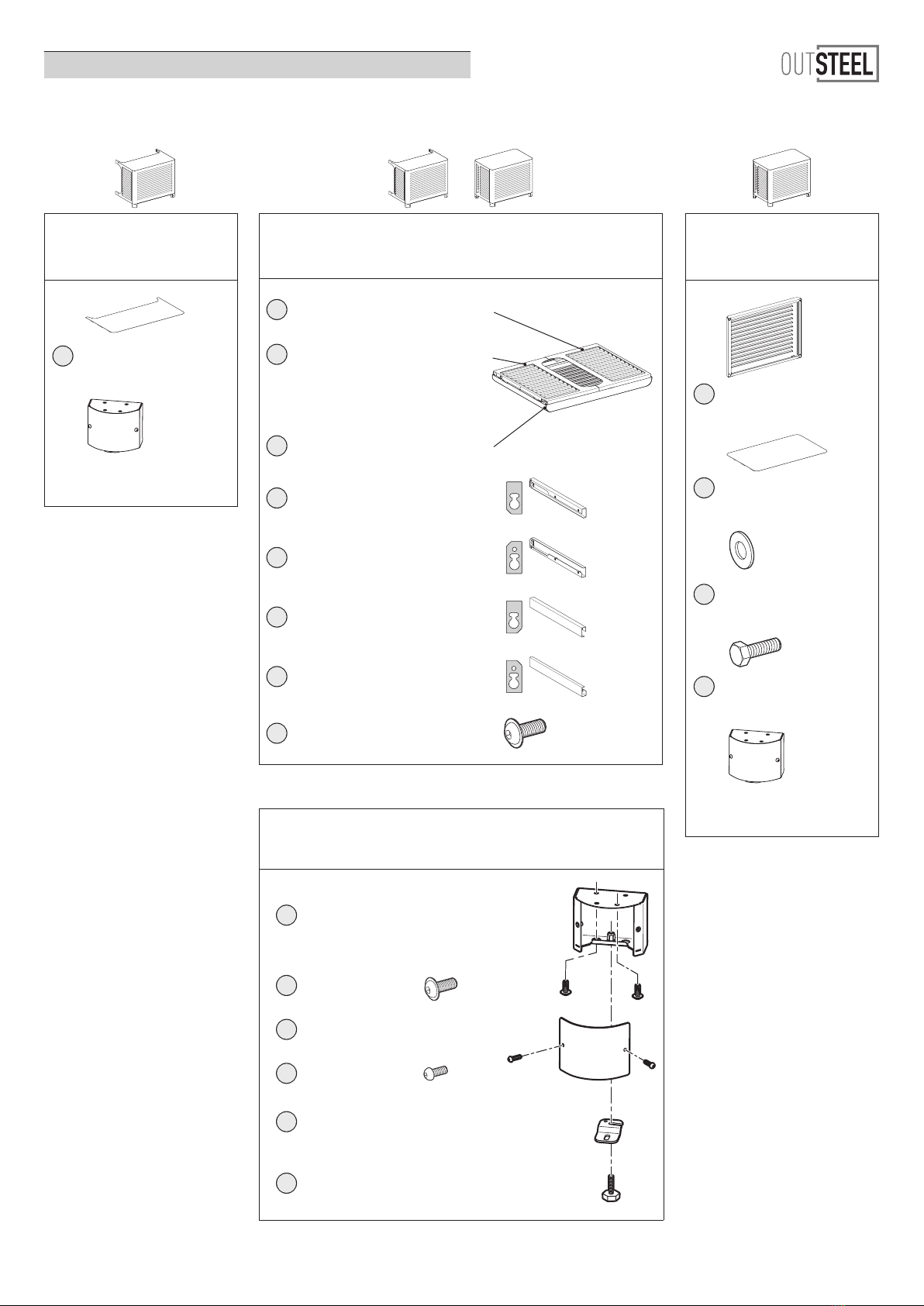
VENITIAN
PRODUIT / PRODUCT
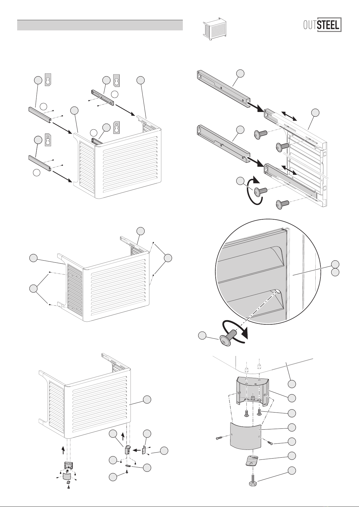
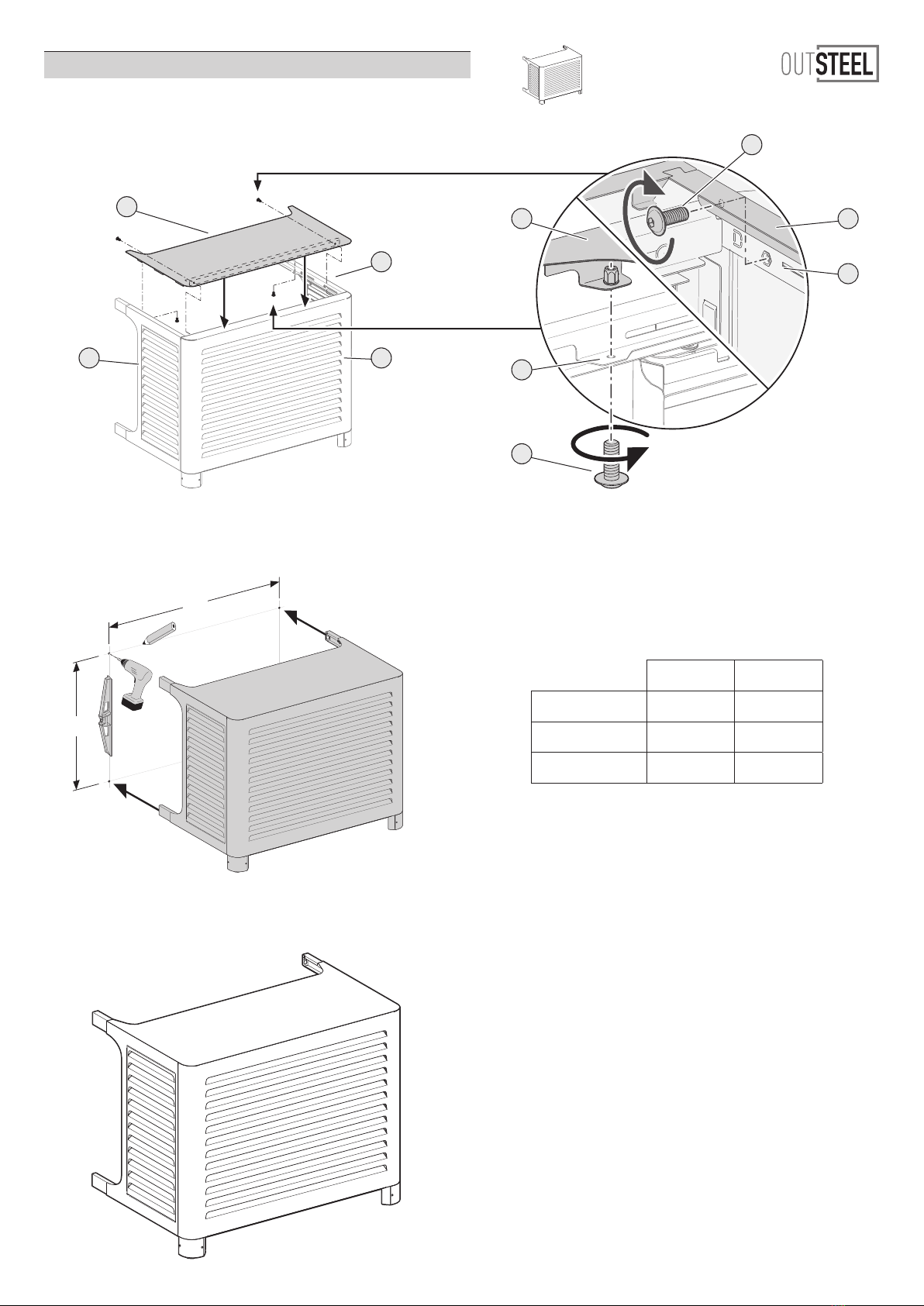
VENITIAN : MONTAGE AU SOL LE LONG D’UN MUR
VENITIAN : FLOOR MOUNTING ALONG A WALL
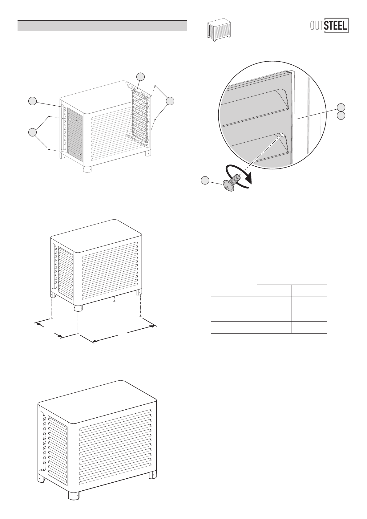
VENITIAN : LORSQUE L’APPAREIL EST ISOLÉ
VENITIAN : WHEN THE DEVICE IS ISOLATED
FR
A lire attentivement. Conserver ces informations pour un usage ultérieur.
!
AVERTISSEMENT
Malgré les précautions de protection, il peut y avoir un risque de
coupure au montage. Pour éviter cela, nous conseillons le port de
gants de sécurité EPI (Equipement de Protection Individuelle).
Les fixations ne sont pas incluses car leur choix dépend du matériau
du mur sur lequel est fixé le cache. Utilisez des fixations adaptées au
matériau du mur et du sol.
Visserie de fixation à prévoir : M6.
Nous vous conseillons des visseries de fixation traitées anti-corrosion.
Prévoir une surface au sol solide et plane, de dimensions suffisantes(*)
pour accueillir l’habillage de votre équipement.
Pour obtenir des conseils sur les fixations à utiliser, adressez-vous à un
revendeur spécialisé.
Nous recommandons la présence de 2 personnes pour le montage.
Ne pas monter sur le produit. Modèle conçu pour supporter une
charge de 15kg maximum.
(*) voir configurateur - dimensions minimales (largeur et profondeur en mm)
variables selon la taille et le modèle retenus.
Règlementation d’installation d’une pompe à chaleur
L’installation d’une pompe à chaleur ou d’une climatisation doit être
réalisée conformément aux recommandations du fabricant et dans le
respect des réglementations en vigueur dans le pays d’installation.
Pour favoriser une circulation d’air optimale, nous conseillons de
laisser le minimum d’espace entre la face avant du cache et l’appareil.
INFORMATION IMPORTANTE / IMPORTANT INFORMATION
GB
Read carefully. Keep this information for further reference.
!
WARNING
Despite the protective precautions, there may be a risk of cuts during
assembly. To avoid this, we recommend wearing PPE (Personal
Protective Equipment) safety gloves.
Fixing devices are not included as their choice depends on the
material of the wall to which the cover is attached. Use fixing devices
suitable for the walls and floor in your home.
Screwing elements (not provided) : M6.
We would recommand you using screwing parts protected against
corrosion
Make sure to have a strong and levelled floor surface, of correct
dimensions(*) for installing the covering on your equipment.
For advice on which fixing devices to use, contact a specialist dealer.
We recommend the presence of 2 people for the mounting.
Do not climb onto the product. Model designed to support a
maximum load of 15kg.
(*) see configurator - minimum dimensions (width and depth in mm) linked to
the size and selected model.
Installation regulations for a heat pump
The installation of a heat pump or air conditioning should be carried
out in accordance with the manufacturer’s recommendations and in
compliance with local codes and standards.
To promote optimal air circulation, we recommend leaving the mini-
mum space between the front of the cover and the device.
OUTILS / TOOLS
Vous munir de / Tools required - not provided :
Clé Allen de 2.5 et 4
2.5mm & 4mm Allen keys
Clé mixte de 10
10mm combination wrench
Niveau à bulle
Spirit level
Perceuse
Drill
Page 6 Page 8