G-U OTS 735 BG User manual

DIN
18040
EN
1154
SPEC 1104
Gleitschienen-Türschließer
Montageanleitung......................................................................... SEITE |
Door closer with slide rail
Assembly instructions ................................................................... PAGE |
Ferme-porte à glissière
Notice de montage ........................................................................ PAGE |
Cierrapuertas con riel de deslizamiento
Instrucciones de montaje........................................................... PÁGINA |
EN
FR
ES
0-45979-PH-0-0
03 | B | 06.2016 | G32381 | Designed in Germany
TÜRTECHNIK | DOOR TECHNOLOGY
OTS BG | OTS BG
DE

2DE EN FR ES
Gleitschienen-Türschließer
Montageanleitung
OTS BG | OTS BG
06.2016 | G32381 | Designed in Germany
. Technische Daten
Technische Daten
Türschließer OTS BG OTS BG
Abmessungen (mit Abdeckhaube) L x H x T in mm 268 x 63 x 44 268 x 63 x 44
Schließkraftgrößen nach EN 1154 2-5 3-6
Anwendung
Flügelbreite 1-flügelig (min. – max.) 600 mm – 1250 mm 600 mm – 1400 mm
Flügelbreite 2-flügelig (min. – max.) 1475 mm – 2500 mm 1475 mm – 2800 mm
DIN links / rechts
Kopfmontage Bandseite
Normalmontage Bandgegenseite (BG)
Zulassung für Feuer- und Rauchschutztüren
Geeignet für barrierefreies Bauen DIN
18040 SPEC 1104 DIN
18040 SPEC 1104
Einstellfunktionen
Schließgeschwindigkeit
Endgeschwindigkeit
Öffnungsdämpfung (ÖD/BC)
Montage / Funktionen
Schließkraft, stufenlos einstellbar
max. Türöffnungswinkel (BS/BG) 2) 180° / 120° 180° / 120°
max. Türöffnungs- und Schließwinkel 180° 180°
Öffnungsbegrenzung ÖB 1) 3) optional optional
Feststellmöglichkeiten
mechanische Feststellung FM, 4)
mit integrierter Öffnungsbegrenzung, überfahrbar
Feststellwinkel, einstellbar optional
stufenlos 80°-140° optional
stufenlos 80°-140°
elektromechanische Feststellung FE, überfahrbar
Feststellwinkel, einstellbar optional
stufenlos 85°-140° optional
stufenlos 85°-140°
1) kein Ersatz für Türpuffer, 2) abhängig von Einbausituation, BS = Bandseite / BG = Bandgegenseite,
3) Nicht in Kombination mit elektromechanischer Feststellung FE, 4) Nicht geeignet für Feuer- und Rauchschutztüren
OTS BG / OTS BG
Inhaltsverzeichnis
. Technische Daten........................................................................Seite
. Leistungserklärungen (DoP) ......................................................Seite
. Komponenten und Zubehör .......................................................Seite
. Montieren und Einstellen...........................................................Seite
4.1 Kopfmontage Bandseite, DIN links ............................................................................Seite 12
4.2 Kopfmontage Bandseite, DIN rechts .........................................................................Seite 14
4.3 Normalmontage Bandgegenseite, DIN links ............................................................Seite 16
4.4 Normalmontage Bandgegenseite, DIN rechts .........................................................Seite 18

3
Begrisdefinitionen / - abkürzungen
Bei der Normalmontage des Türschließers an Feuer- und Rauchschutztüren muss die
Montageplatte verwendet werden!
HINWEIS
Bei Einsatz an Feuer- und Rauchschutztüren sind die Einbauanleitungen des Herstellers sowie
die EN zu beachten!
VORSICHT
AD Abdeckhaube/Abdeckung
AV Achsverlängerung
BG Bandgegenseite
BS Bandseite
Fgeprüft nach EN 1154 und einsetzbar an Feuer- und Rauchschutztür
FE Feststellung, elektromechanisch
FM Feststellung, mechanisch
GS Gleitschiene
MP Montageplatte
ÖB Öffnungsbegrenzung
ÖD/BC Öffnungsdämpfung / Backcheck
OTS Obentürschließer
RSM Rauchschaltmodul
SRI Schließfolgeregler, integriert
SW Schlüsselweite
. Leistungserklärungen (DoP)
Originalanleitung
Bitte geben Sie das Dokument an den Benutzer weiter!
Leistungserklärungen finden Sie auf der GU-Homepage "www.g-u.com" unter dem Punkt
"Service" im Register "Bauproduktenverordnung / CPR":
www.g-u.com/de/service/bauproduktenverordnung.html
HINWEIS
Für das Produkt gelten die nachfolgend aufgeführten Leistungserklärungen:
0017-CPR-GU-BKS-Ferco
0026-CPR-GU-BKS-Ferco
Beachten Sie auch die "Produktinformation Türschließer OTS | UTS | VTS" (Art.-Nr. --P--).
Sie finden das Dokument auf der GU-Homepage "www.g-u.com" unter dem Punkt "SERVICE" im
Register "Downloads" (www.g-u.com/de/service/downloads.html).
HINWEIS

4DE EN FR ES
Door closer with slide rail
Assembly instructions
OTS BG | OTS BG
06.2016 | G32381 | Designed in Germany
. Technical data
Table of contents
. Technical data ............................................................................. Page
. Declarations of performance (DoP)........................................... Page
. Components and accessories..................................................... Page
. Installing and adjusting .............................................................. Page
4.1 Standard installation on hinge side, DIN left............................................................Page 12
4.2 Standard installation on hinge side, DIN right .........................................................Page 14
4.3 Transom installation on side opposite to hinges, DIN left .....................................Page 16
4.4 Transom installation on side opposite to hinges, DIN right...................................Page 18
Technical data
Door closer OTS BG OTS BG
Dimensions (with cover) L x H x D in mm 268 x 63 x 44 268 x 63 x 44
Closing force sizes according to EN 1154 2-5 3-6
Application range
Door leaf width, 1-leaf (min. – max.) 600 mm – 1250 mm 600 mm – 1400 mm
Door leaf width, 2-leaf (min. – max.) 1475 mm – 2500 mm 1475 mm – 2800 mm
DIN left/right
Transom installation on hinge side
Standard installation on side opposite to hinges (BG)
Approval for fire and smoke protection doors
Suitable for barrier-free construction DIN
18040 SPEC 1104 DIN
18040 SPEC 1104
Adjustment functions
Closing speed
Latching speed
Backcheck (ÖD/BC)
Installation/functions
Steplessly adjustable closing force
Maximum door opening angle (BS/BG) 2) 180° / 120° 180° / 120°
Maximum door opening and closing angle 180° 180°
Opening restriction ÖB 1) 3) optional optional
Hold-open options
mechanical hold-open device FM 4)
with integrated opening restrictor,
opening beyond hold-open angle possible, adjustable hold-open angle optional
stepless 80°-140° optional
stepless 80°-140°
electromechanical hold-open device (FE),
opening beyond hold-open angle possible, adjustable hold-open angle optional
stepless 85°-140° optional
stepless 85°-140°
1) no substitute for door stop, 2) Depends on installation situation, BS = hinge side / BG = side opposite to hinges,
3) Not in conjunction with electromechanical hold-open device FE, 4) Not suitable for fire and smoke protection doors
OTS BG / OTS BG

5
Translation of the original instructions
Please pass the document on to the user
. Declarations of performance (DoP)
Definitions of terms/abbreviations
For standard installation of the door closer on fire and smoke protection doors, the mounting
plate must be used!
NOTE
When using the door closer on fire and smoke protection doors, the installation instructions of
the manufacturer and EN must be observed!
CAUTION
AD ("Abdeckhaube/Abdeckung") cover
AV ("Achsverlängerung") axle extension
BG ("Bandgegenseite") side opposite to hinges
BS ("Bandseite") hinge side
FTested to EN 1154 and used for fire and smoke
protectiondoors
FE ("Feststellung, elektromechanisch") hold-open, electromechanical
FM ("Feststellung, mechanisch") hold-open, mechanical
GS ("Gleitschiene") slide rail
MP ("Montageplatte") mounting plate
ÖB ("Öffnungsbegrenzung") opening restriction
ÖD/BC ("Öffnungsdämpfung / Backcheck") backcheck
OTS ("Obentürschließer") overhead door closer
RSM ("Rauchschaltmodul") smoke switch module
SRI ("Schließfolgeregler, integriert") door leaf coordinator, integrated
SW ("Schlüsselweite") size
The following Declarations of Permormance apply to this product:
0017-CPR-GU-BKS-Ferco
0026-CPR-GU-BKS-Ferco
Declarations of Performance can be found at the GU website "www.g-u.com" in the menu item
"Construction Products Regulation / CPR" under "Services":
www.g-u.com/en/services/construction-products-regulation.html
NOTE
Also observe the product information --P-- "OTS | UTS | VTS – Door closer".
You will find the document at www.g-u.com under "SERVICES" in the menu item "Downloads".
NOTE

6DE EN FR ES
Ferme-porte à glissière
Notice de montage
OTS BG | OTS BG
06.2016 | G32381 | Designed in Germany
. Caractéristiques techniques
Table des matières
. Caractéristiques techniques ...................................................... Page
. Déclarations des performances (DoP)....................................... Page
. Composants et accessoires ........................................................ Page
. Montage et réglage .................................................................... Page
4.1 Montage normal côté paumelles, DIN gauche.........................................................Page 12
4.2 Montage normal côté paumelles, DIN droite...........................................................Page 14
4.3 Montage inversé côté opposé aux paumelles, DIN gauche ...................................Page 16
4.4 Montage inversé côté opposé aux paumelles, DIN droite .....................................Page 18
Caractéristiques techniques
Ferme-portes OTS BG OTS BG
Dimensions (avec capot) l x H x P en mm 268 x 63 x 44 268 x 63 x 44
Force de fermeture selon EN 1154 2-5 3-6
Application
Largeur du vantail pour 1 vantail (min. – max.) 600 mm – 1250 mm 600 mm – 1400 mm
Largeur du vantail pour 2 vantaux (min. – max.) 1475 mm – 2500 mm 1475 mm – 2800 mm
DIN droite / à gauche
Montage inversé côté paumelles
Montage normal côté opposé aux paumelles (BG)
Homologation pour portes coupe-feu et pare-fumée
Conformité aux règles d’accessibilité dans la construction DIN
18040 SPEC 1104 DIN
18040 SPEC 1104
Fonctions réglables
Vitesse de fermeture
Vitesse terminale
Freinage à l‘ouverture (ÖD/BC)
Montage / Fonctions
Force de fermeture, réglable en continu
Angle max. d‘ouverture de porte (BS/BG) 2) 180° / 120° 180° / 120°
Angle max. d‘ouverture et de fermeture de porte 180° 180°
Limitation d‘ouverture ÖB 1) 3) en option en option
Possibilités d‘arrêt
Arrêt mécanique FM, 4)
avec limiteur d’ouverture integer, surmontable
Angle d‘arrêt réglable en option
en continu 80°-140° en option
en continu 80°-140°
Arrêt électromécanique FE, surmontable
Angle d‘arrêt réglable en option
en continu 85°-140° en option
en continu 85°-140°
1) ne remplace pas le butoir de porte, 2) en fonction de la situation de montage, BS = côté paumelles / BG = côté opposé aux paumelles,
3) pas en liaison avec un arrêt électromécanique FE, 4) ne convient pas aux portes coupe-feu et pare-fumée
OTS BG / OTS BG

7
Originalanleitung
Bitte geben Sie das Dokument an den Benutzer weiter!
. Déclarations des performances (DoP)
Traduction de la notice d‘origine
Veuillez transmettre ce document à l‘utilisateur!
Définitions des termes et abréviations
En cas de montage normal du ferme-porte sur des portes coupe-feu et pare-fumée, il faut
utiliser la plaque de montage!
REMARQUE
En cas d‘utilisation sur portes coupe-feu et pare-fumée, les instructions de montage du fabricant
ainsi que la norme EN doivent être respectées!
PRUDENCE
AD Capot/Revêtement
AV Rallonge d‘axe
BG Côté opposé aux paumelles
BS Côté paumelles
FCertifié selon EN 1154 et utilisable sur portes coupe-feu et pare-fumée
FE Arrêt électromécanique
FM Arrêt mécanique
GS Glissière
MP Plaque de montage
ÖB Limitation d‘ouverture
ÖD/BC Freinage à l‘ouverture / Backcheck
OTS Ferme-porte
RSM Détecteur de fumée
SRI Sélecteur de fermeture intégré
SW Ouverture de clé, surplat
Pour le produit, les déclarations de performance suivantes s'appliquent :
0017-CPR-GU-BKS-Ferco
0026-CPR-GU-BKS-Ferco
Vous trouverez des déclarations de performance sur le site web de GU"www.g-u.com" au point
"Service" sous l'option "Règlement produits de construction / RPC" :
www.g-u.com/fr/services/reglement-produits-de-construction.html
REMARQUE
Tenez également compte des informations produits --P-- "OTS | UTS | VTS – Ferme-
porte". Yous trouverez le document sur www.g-u.com sous le menu "SERVICES" et le sous-menu
"Téléchargements".
REMARQUE

8DE EN FR ES
Cierrapuertas con riel de deslizamiento
Instrucciones de montaje
OTS BG | OTS BG
06.2016 | G32381 | Designed in Germany
. Datos técnicos
Índice de contenido
. Datos técnicos.......................................................................... Página
. Declaraciones de rendimiento (DoP)...................................... Página
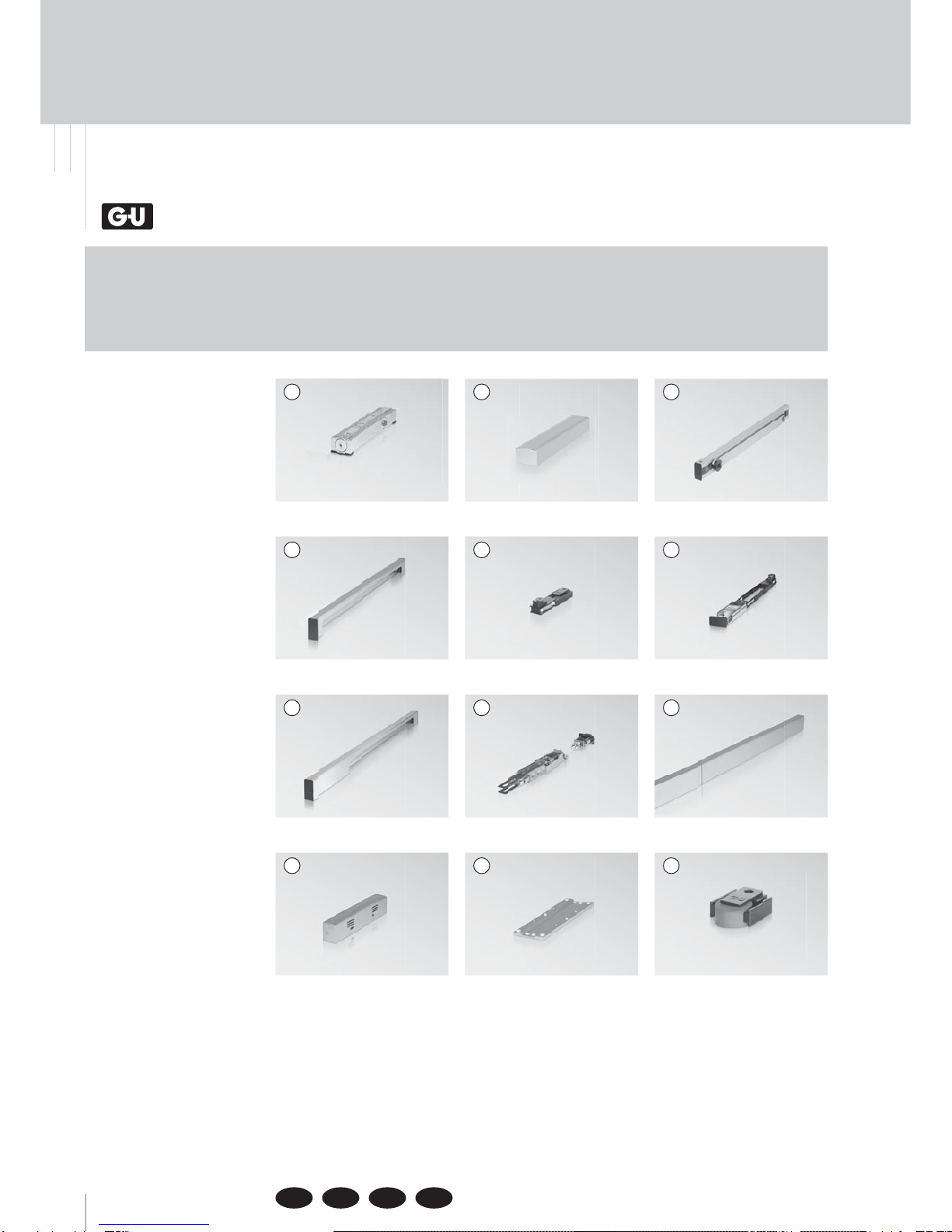
. Componentes yaccesorios...................................................... Página
. Montaje y ajuste ......................................................................Página
4.1 Montaje normal en el lado de las bisagras, DIN izquierda ..................................Página 12
4.2 Montaje normal en el lado de las bisagras, DIN derecha.....................................Página 14
4.3 Montaje invertido en el lado contrario al de las bisagras, DIN izquierda .........Página 16
4.4 Montaje invertido en el lado contrario al de las bisagras, DIN derecha............Página 18
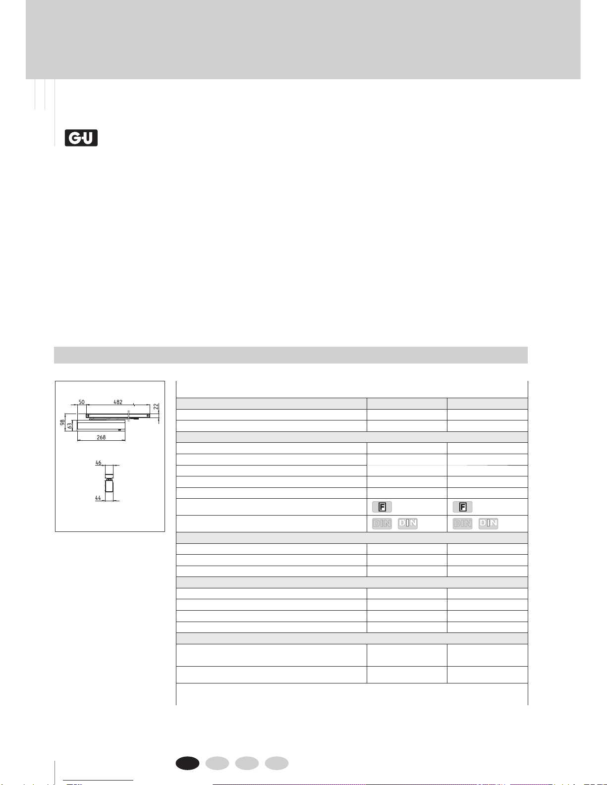
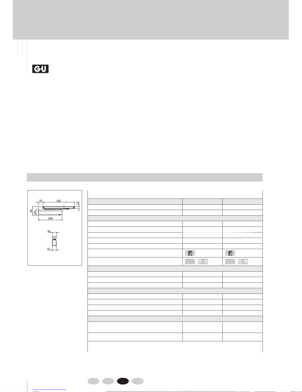
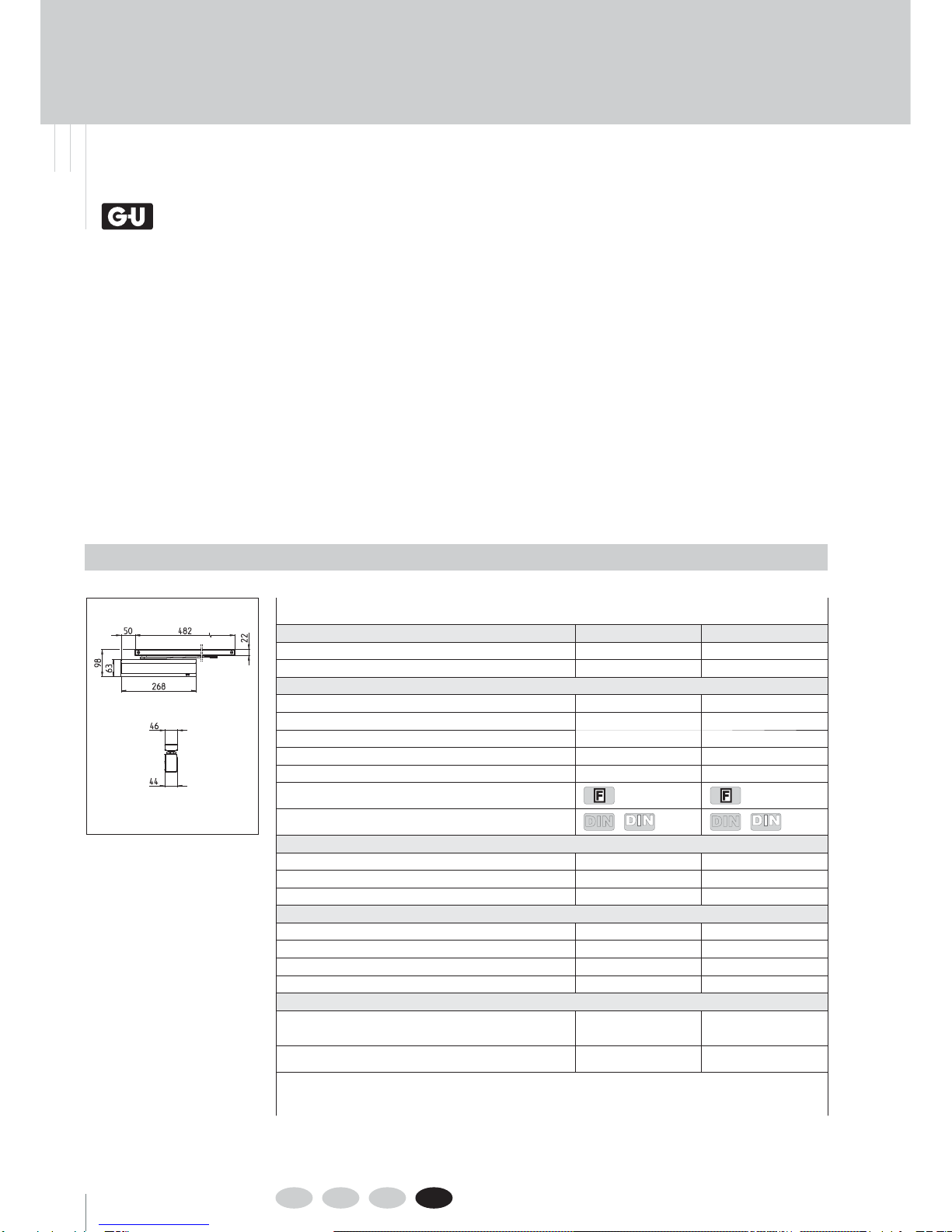
Datos técnicos
Cierrapuertas OTS BG OTS BG
Dimensiones (con cubierta) largo x alto x profundidad en mm 268 x 63 x 44 268 x 63 x 44
Magnitudes de la fuerza de cierre según EN 1154 2-5 3-6
Aplicación
Anchura de hoja en puertas de una hoja (mín. – máx.) 600 mm – 1250 mm 600 mm – 1400 mm
Anchura de hoja en puertas de 2 hojas (mín. – máx.) 1475 mm – 2500 mm 1475 mm – 2800 mm
DIN izquierda / derecha
Montaje invertido en el lado de las bisagras
Montaje normal en el lado contrario al de las bisagras (BG)
Autorización para puertas cortafuegos ycortahumos
Indicado para construcciones sin barreras arquitectónicas DIN
18040 SPEC 1104 DIN
18040 SPEC 1104
Funciones de ajuste
Velocidad de cierre
Velocidad final
Frenado a la apertura (ÖD/BC)
Montaje / funciones
Fuerza de cierre, posibilidad de ajuste continuo
Ángulo máx. de apertura de la puerta (BS/BG) 2) 180° / 120° 180° / 120°
Ángulo máx. de apertura ycierre de la puerta 180° 180°
Limitación de apertura (ÖB) 1) 3) Opcional Opcional
Posibilidades de retención
Mecanismo mecánico de retención (FM), 4)
con limitador de apertura integrado, puenteable
Ángulo de retención, ajustable Opcional
Continuo 80°-140° Opcional
Continuo 80°-140°
Mecanismo electromecánico de retención (FE), puenteable
Ángulo de retención, ajustable Opcional
Continuo 85°-140° Opcional
Continuo 85°-140°
1) No reemplaza los topes para puertas,
2) En función de la posición de montaje, BS = lado de las bisagras / BG = lado contrario al de las bisagras,
3) No en combinación con un mecanismo electromecánico de retención (FE), 4) No apto para puertas cortafuegos ycortahumos
OTS BG / OTS BG

9
Traducción de las instrucciones originales
¡Entregue este documento al usuario!
. Declaraciones de rendimiento (DoP)
Definiciones/abreviaturas de los términos
¡En el montaje normal del cierrapuertas en puertas cortafuegos ycortahumos se debe utilizar la
placa de montaje!
NOTA
¡En caso de aplicación en puertas cortafuegos ycortahumos se deberán observar las
instrucciones de montaje del fabricante así como la EN !
PRECAUCIÓN
AD Cubierta/recubrimiento
AV Prolongación del eje
BG Lado contrario al de las bisagras
BS Lado de las bisagras
FProbado conforme aEN 1154 yaplicable en puertas cortafuegos ycortahumos
FE Mecanismo electromecánico de retención
FM Mecanismo mecánico de retención
GS Riel de deslizamiento
MP Placa de montaje
ÖB Limitación de apertura
ÖD/BC Frenado ala apertura/backcheck
OTS Cierrapuertas aéreo
RSM Módulo de conmutación en caso de humo
SRI Regulador coordinador de cierre integrado
SW Tamaño
Las siguientes declaraciones de rendimiento se aplican al producto:
0017-CPR-GU-BKS-Ferco
0026-CPR-GU-BKS-Ferco
Declaraciones de rendimiento se pueden encontrar en la página web de GU "www.g-u.com" bajo
"Servicios" en el elemento de menú "Reglamento de Productos de Construcción / RPC":
www.g-u.com/es/servicios/reglamento-de-productos-de-construccion.html
NOTA
Tenga también en cuenta las informaciones de producto --P-- "OTS | UTS | VTS –
Cierrapuertas".
Encontrará el documento en www.g-u.com en "SERVICIOS" en el punto de menú "Descargas".
NOTA

10 DE EN FR ES
OTS BG | OTS BG
06.2016 | G32381 | Designed in Germany
. Komponenten und Zubehör
. Components and accessories
. Componentes yaccesorios
. Composants et accessoires
OTS 736 BG K-18346-00-0
OTS 735 BG K-18344-00-0
K-18369-00-0K-18364-00-0
K-18351-00-0K-18338-00-0
K-18368-00-0
K-18916-00-0K-18280-00-0K-19058-00-0
K-18367-00-0K-18835-00-0K-18365-00-0
OTS x AD-OTS x
FE
AD-SRI
GS
AD-GS-FE
RSM
AD-GS
SRI-BG
MP
FM
ÖB
a b

11
AD-GS
GS
OTS X
FM/ÖB
MP
OTS X MP
OTS X OTS X
MP MP
x Set OTS x: Set OTS BG (OTS 736 BG + AD-OTS 73x) K-18501-00-0
Set OTS BG (OTS 735 BG + AD-OTS 73x) K-18499-00-0
Set OTS BG (OTS 733 BG + AD-OTS 73x) K-18497-00-0
Set GS SRI-OTS x BG (2xGS + 2xAD-GS + SRI-BG + AD-SRI) K-18357-00-0
Set GS FE-SRI-OTS x BG
(2xGS + 2xFE + 2xAD-GS-FE + SRI-BG + AD-SRI)
K-18358-00-0
Set GS FER-SRI-OTS x BG
(2xGS
+
2xFE
+
2xAD-GS-FE
+
SRI-BG
+
AD-SRI
+
RSM)
K-18359-00-0
Set OTS BG
(OTS 736 BG
+
AD-OTS 73x
+
GS)
K-18363-00-0
Set OTS BG
(OTS 735 BG
+
AD-OTS 73x
+
GS)
K-18361-00-0
Option: AD-GS K-18364-00-0
FM K-18369-00-0
ÖB K-18916-00-0
MP K-18280-00-0
Set OTS BG
(OTS 736 BG + AD-OTS 73x)
K-18501-00-0
Set OTS BG
(OTS 735 BG + AD-OTS 73x)
K-18499-00-0
Option: MP K-18280-00-0
Set GS FE-OTS x K-18352-00-0
(FE + GS + AD-GS-FE)
Set GS FER-OTS x K-18353-00-0
(FE + GS + AD-GS-FE + RSM)
R
S
M
A
D
-GS-F
E
G
S
F
E
AD-GS-FE
GS
FE
RSM
AD-GS-FE
GS
FE
Set
OTS+GS
Set OTS
Set OTS
Set GS
Set GS
R
S
M
AD-GS-FE
GS
FE GS FE
AD-SRI SRI AD-GS-FE
RSM
SRI
SRI-BG
AD-GS-FE
GS
FE GS FE
AD-SRI
SRI
AD-GS-FE
SRI-BG
AD-GS AD-SRI
GS SRI
AD-GS
GS
FM FM
//
ÖB ÖB
SRI-BG
A
D
-
GS
A
D-
S
R
I
G
S
S
R
I
A
D
-
GS
G
S
-BG
MP
MP
OTS
X
OTS
X
MP MP
MP MP
MP MP
O
T
S
X
OTS
X
OTS
X
O
T
S
X
OTS
X
OTS
X
Option: 2x MP 2x K-18280-00-0
Option: 2x FM 2x K-18369-00-0
2x ÖB 2x K-18916-00-0

12 DE EN FR ES
OTS BG | OTS BG
06.2016 | G32381 | Designed in Germany
( )
( )
a b
Bohrlehre (optional)
Drilling jig (optional)
Gabarit de perçage (en option)
Plantilla de taladro (opcional)
Anschlagschablone
Mounting template
Gabarit de pose
Plantilla de montaje
K-189389-47509-02-0
K-18280
. Montieren und Einstellen
. Installing and adjusting
. Montage et réglage
. Montaje y ajuste
14
4
48
83-6
2-5 1
11
14
4
Dangerous substances: None
Gretsch-Unitas GmbH
Baubeschläge
Johann-Maus-Str. 3
D-71254 Ditzingen
EN 1154:1996
+A1:2002
0432-CPR-
00184-01
. Kopfmontage Bandseite, DIN links
. Transom installation on hinge side, DIN left
. Montage inversé côté paumelles, DIN gauche
. Montaje invertido en el lado de las bisagras, DIN izquierda
Mit
With
Avec
Con
MP
DIN links
DIN left
OTS 73x BG DIN rechts
DIN right
OTS 73x BG
max. 10 max. 26
!
OTS
BG
EN
www.g-u.com
---L
2
1
3
ÖD
BC
1
3
EN -
°
°
°
°
DIN
EN
SW
Size
6 Pans
Tamaño
6 Nm
4
!

13
OTS
BG
EN
www.g-u.com
---L
2
1
3
ÖD
BC
1
3
EN -
°
°
°
°
DIN
EN
1
2
3
max. 180°
1
2
3
OTS
BG
EN
www.g-u.com
---L
2
1
3
ÖD
BC
1
3
EN-
°
°
°
°
DIN
EN
a b Mit
With
Avec
Con
K-18280
SW
Size
6 Pans
Tamaño
4 Nm
OTS
BG
EN
www.g-u.com
---L
2
1
3
ÖD
BC
1
3
EN-
°
°
°
°
DIN
EN
OTS
BG
EN
www.g-u.com
---L
2
1
3
ÖD
BC
1
3
EN-
°
°
°
°
DIN
EN
DIN
EN
OTS BG
SW
Size
6 Pans
Tamaño
SW
Size
6 Pans
Tamaño
5
5
DIN
EN
OTS BG
OTS
BG
www.g-u.com
---L
1
3
DIN
EN
Schließkraft
Closing force
Force de fermeture
Fuerza de cierre
EN B
2 ≤ 850 mm
3 ≤ 950 mm
4 ≤ 1100 mm
5 ≤ 1250 mm
6 ≤ 1400 mm
min. EN 3
DIN
18040 max. EN 4,5
MP
4
!
!
!

14 DE EN FR ES
OTS BG | OTS BG
06.2016 | G32381 | Designed in Germany
. Kopfmontage Bandseite, DIN rechts
. Transom installation on hinge side, DIN right
. Montage inversé côté paumelles, DIN droite
. Montaje invertido en el lado de las bisagras, DIN derecha
( )
( )
Bohrlehre (optional)
Drilling jig (optional)
Gabarit de perçage (en option)
Plantilla de taladro (opcional)
Anschlagschablone
Mounting template
Gabarit de pose
Plantilla de montaje
9-47509-02-0
14
4
48
83-6
2-5 1
11
14
4
Dangerous substances: None
Gretsch-Unitas GmbH
Baubeschläge
Johann-Maus-Str. 3
D-71254 Ditzingen
EN 1154:1996
+A1:2002
0432-CPR-
00184-01
a b K-18280
Mit
With
Avec
Con
MP
DIN links
DIN left
OTS 73x BG DIN rechts
DIN right
OTS 73x BG
K-18938
OTS
BG
EN
www.g-u.com
---L
2
1
3
ÖD
BC
1
3
EN -
°
°
°
°
DIN
EN
6 Nm
SW
Size
6 Pans
Tamaño
4
max. 10
max. 10
max. 26
max. 26
!
!

15
OTS
BG
EN
www.g-u.com
---L
2
1
3
ÖD
BC
1
3
EN-
°
°
°
°
DIN
EN
4 Nm
OTS
BG
EN
www.g-u.com
---L
2
1
3
ÖD
BC
1
3
EN-
°
°
°
°
DIN
EN
OTS
BG
EN
www.g-u.com
---L
2
1
3
ÖD
BC
1
3
EN-
°
°
°
°
DIN
EN
OTS
BG
EN
www.g-u.com
---L
2
1
3
ÖD
BC
1
3
EN -
°
°
°
°
DIN
EN
1
2
3max. 180°
1
2
3
DIN
EN
DIN
EN
OTS
BG
www.g-u.com
---L
1
3
DIN
EN
OTS BG
OTS BG
Schließkraft
Closing force
Force de fermeture
Fuerza de cierre
EN B
2 ≤ 850 mm
3 ≤ 950 mm
4 ≤ 1100 mm
5 ≤ 1250 mm
6 ≤ 1400 mm
min. EN 3
DIN
18040 max. EN 4,5
a b Mit
With
Avec
Con
K-18280
SW
Size
6 Pans
Tamaño
MP
4
SW
Size
6 Pans
Tamaño
SW
Size
6 Pans
Tamaño
5
5
!
!
!

16 DE EN FR ES
OTS BG | OTS BG
06.2016 | G32381 | Designed in Germany
. Normalmontage Bandgegenseite, DIN links
. Standard installation on side opposite to hinges, DIN left
. Montage normal côté opposé aux paumelles, DIN gauche
. Montaje normal en el lado contrario al de las bisagras, DIN izquierda
Bohrlehre (optional)
Drilling jig (optional)
Gabarit de perçage (en option)
Plantilla de taladro (opcional)
K-18937
Anschlagschablone
Mounting template
Gabarit de pose
Plantilla de montaje
9-47509-01-0
14
3
38
83-6
2-5 1
11
14
4
Dangerous substances: None
Gretsch-Unitas GmbH
Baubeschläge
Johann-Maus-Str. 3
D-71254 Ditzingen
EN 1154:1996
+A1:2002
0432-CPR-
00184-01
( )
( )
a b K-18280
Mit
With
Avec
Con
MP
DIN links
DIN left
OTS 73x BG
DIN rechts
DIN right
OTS 73x BG
OTS
BG
EN
www.g-u.com
---L
2
1
3
ÖD
BC
1
3
EN -
°
°
°
°
DIN
EN
6 Nm
SW
Size
6 Pans
Tamaño
4
max. 10
max. 10
max. 26
max. 26
!
!

17
OTS
BG
EN
www.g-u.com
---L
2
1
3
ÖD
BC
1
3
EN-
°
°
°
°
DIN
EN
OTS
BG
EN
www.g-u.com
---L
2
1
3
ÖD
BC
1
3
EN-
°
°
°
°
DIN
EN
OTS
BG
EN
www.g-u.com
---L
2
1
3
ÖD
BC
1
3
EN-
°
°
°
°
DIN
EN
4 Nm
a b Mit
With
Avec
Con
K-18280
SW
Size
6 Pans
Tamaño
MP
4
DIN
EN
DIN
EN
OTS
BG
www.g-u.com
---L
1
3
DIN
EN
OTS BG
OTS BG
Schließkraft
Closing force
Force de fermeture
Fuerza de cierre
EN B
2 ≤ 850 mm
3 ≤ 950 mm
4 ≤ 1100 mm
5 ≤ 1250 mm
6 ≤ 1400 mm
min. EN 3
DIN
18040 max. EN 4,5
SW
Size
6 Pans
Tamaño
SW
Size
6 Pans
Tamaño
5
5
OTS
BG
EN
www.g-u.com
---L
2
1
3
ÖD
BC
1
3
EN -
°
°
°
°
DIN
EN
1
2
3
Türstopper
Doorstop
Butoir de porte
Tope de puerta
B
Į
1
2α
3
XOTS
max. α *
OTS + FM
max. α *
70 mm 125° 113°
80 mm 121° 110°
90 mm 117° 108°
100 mm 113° 106°
110 mm 110° 103°
*bei glattschlagenden Türen.
Bei nicht glattschlagenden Türen ist max. α geringfügig kleiner.
*with flush doors
Max. α is slightly smaller with overlapping doors.
*pour portes affleurantes
En cas de portes avec recouvrement, max α est légèrement
inférieur.
*para puertas enrasadas
En caso de portas con solapa, máx. α estará ligeramente inferior.
!!
!

18 DE EN FR ES
OTS BG | OTS BG
06.2016 | G32381 | Designed in Germany
. Normalmontage Bandgegenseite, DIN rechts
. Standard installation on side opposite to hinges, DIN right
. Montage normal côté opposé aux paumelles, DIN droite
. Montaje normal en el lado contrario al de las bisagras, DIN derecha
( )
( )
Bohrlehre (optional)
Drilling jig (optional)
Gabarit de perçage (en option)
Plantilla de taladro (opcional)
Anschlagschablone
Mounting template
Gabarit de pose
Plantilla de montaje
9-47509-01-0
14
3
38
83-6
2-5 1
11
14
4
Dangerous substances: None
Gretsch-Unitas GmbH
Baubeschläge
Johann-Maus-Str. 3
D-71254 Ditzingen
EN 1154:1996
+A1:2002
0432-CPR-
00184-01
a b K-18280
Mit
With
Avec
Con
MP
DIN links
DIN left
OTS 73x BG
DIN rechts
DIN right
OTS 73x BG
K-18937
OTS
BG
EN
www.g-u.com
---L
2
1
3
ÖD
BC
1
3
EN -
°
°
°
°
DIN
EN
6 Nm
SW
Size
6 Pans
Tamaño
4
max. 10 max. 26
!
!

19
OTS
BG
EN
www.g-u.com
---L
2
1
3
ÖD
BC
1
3
EN-
°
°
°
°
DIN
EN
4 Nm
OTS
BG
EN
www.g-u.com
---L
2
1
3
ÖD
BC
1
3
EN-
°
°
°
°
DIN
EN
OTS
BG
EN
www.g-u.com
---L
2
1
3
ÖD
BC
1
3
EN-
°
°
°
°
DIN
EN
a b Mit
With
Avec
Con
K-18280
SW
Size
6 Pans
Tamaño
MP
4
DIN
EN
DIN
EN
OTS
BG
www.g-u.com
---L
1
3
DIN
EN
OTS BG
OTS BG
Schließkraft
Closing force
Force de fermeture
Fuerza de cierre
EN B
2 ≤ 850 mm
3 ≤ 950 mm
4 ≤ 1100 mm
5 ≤ 1250 mm
6 ≤ 1400 mm
min. EN 3
DIN
18040 max. EN 4,5
SW
Size
6 Pans
Tamaño
SW
Size
6 Pans
Tamaño
5
5
OTS
BG
EN
www.g-u.com
---L
2
1
3
ÖD
BC
1
3
EN -
°
°
°
°
DIN
EN
1
2
3
Türstopper
Doorstop
Butoir de porte
Tope de puerta
B
Į
1
2
α
3
XOTS
max. α *
OTS + FM
max. α *
70 mm 125° 113°
80 mm 121° 110°
90 mm 117° 108°
100 mm 113° 106°
110 mm 110° 103°
*bei glattschlagenden Türen.
Bei nicht glattschlagenden Türen ist max. α geringfügig kleiner.
*with flush doors
Max. α is slightly smaller with overlapping doors.
*pour portes affleurantes
En cas de portes avec recouvrement, max α est légèrement
inférieur.
*para puertas enrasadas
En caso de portas con solapa, máx. α estará ligeramente inferior.
!!
!

Herausgeber | Editor:
Gretsch-Unitas GmbH
Baubeschläge
Johann-Maus-Str. 3
D-71254 Ditzingen
Tel. +49(0)7156 301-0
Fax +49(0)7156 301-
293
www.g-u.com
Fehler, Irrtümer und technische Änderungen vorbehalten.
Errors and omissions reserved. Subject to technical modifications.
Sous réserve d‘erreurs et de modifications techniques.
Reservado el derecho a realizar modificaciones técnicas. Salvo error u omission.
OTS BG / OTS BG
This manual suits for next models
5
Table of contents
Languages:
Other G-U Door Opening System manuals
Popular Door Opening System manuals by other brands

Beninca
Beninca VN.45EL Operating instructions and spare parts catalogue

GEZE
GEZE Slimdrive EMD Replacement instructions

Assa Abloy
Assa Abloy Sargent 2409 Series Wiring instructions

Dynasty
Dynasty DYN-2000 installation instructions

Lock
Lock L5241AL installation instructions

Eco
Eco TS-41 Assembly instruction