gagalight RGB4000 User manual

第1页
User Manual
RGB4000 laser light
Introduction
Thank you for purchasing our product.
To ensure proper operation, please read this manual carefully before using the
product.
After reading it, keep it in a safe place for future reference.

第2页
*The following chapters explain important information about lasers in general,
basic laser safety and some tips about how to use this device correctly.
Please spend some time reading these information as some of them are critical for
safe and efficient operation of this laser display system.
General Information

第3页
!This laser entertainment system is rated as a Class IV laser product and manufactured
in accordance to EN 60825-1:2007. Avoid eye or skin exposure to direct or scattered
radiation. Wear protective goggles of suitable optical density if necessary.
!If the laser is operated in a situation where health or property injury may occur the
operation must be stopped immediately.
!The manufacturer and its distributors cannot be held responsible for any damages
caused by improper use or misuse of this laser system. The owner/user is fully
responsible for using this product in accordance to laser safety regulations of the
country or state where the system is being used.
Caution
Please note that some other optical devices such as cameras, camcorders, video projector etc.
can be damaged if exposed to excessive laser radiation.
Handling precautions
This laser system is a precision device that contains some sensitive opto-electronics components.
DO NOT drop it or subject it to physical shock.
This laser system is not waterproof or dust-proof. Make sure to use an appropriate cover or
enclosure if it is used in the rain, snow or similar severe environment conditions.
Do not leave the laser system in excessive heat such as in a car whilst in direct sunlight. High
temperatures could cause some serious damage to the system.
The laser system contains precision electronic circuitry. Never attempt to disassemble the laser
yourself.
If the laser is suddenly brought in from the cold into a warm room, condensation may form on
the laser and internal parts. If condensation forms on the laser body, do not use the laser as this
may damage the laser system. If there is condensation, wait until it has evaporated before using
it.

第4页
What is a laser and how does it work?
What is a LASER?
The laser is a bunch of energy waves (streams of photons called radiation) with the same
amplitude and faze that are flowing in the same direction; meaning they are coherent –they
stick together and form a laser beam.
The width of a single wave is measured in nano-meters and defines the colour and visibility of the
laser beam. The visible spectrum of the human eye is roughly between 400nm and 700nm, going
from violet to a dark red colour. A human eye is most sensitive to a green light of around 555nm,
meaning that a 1W of green laser will always appear more visible than 1W of any other colour
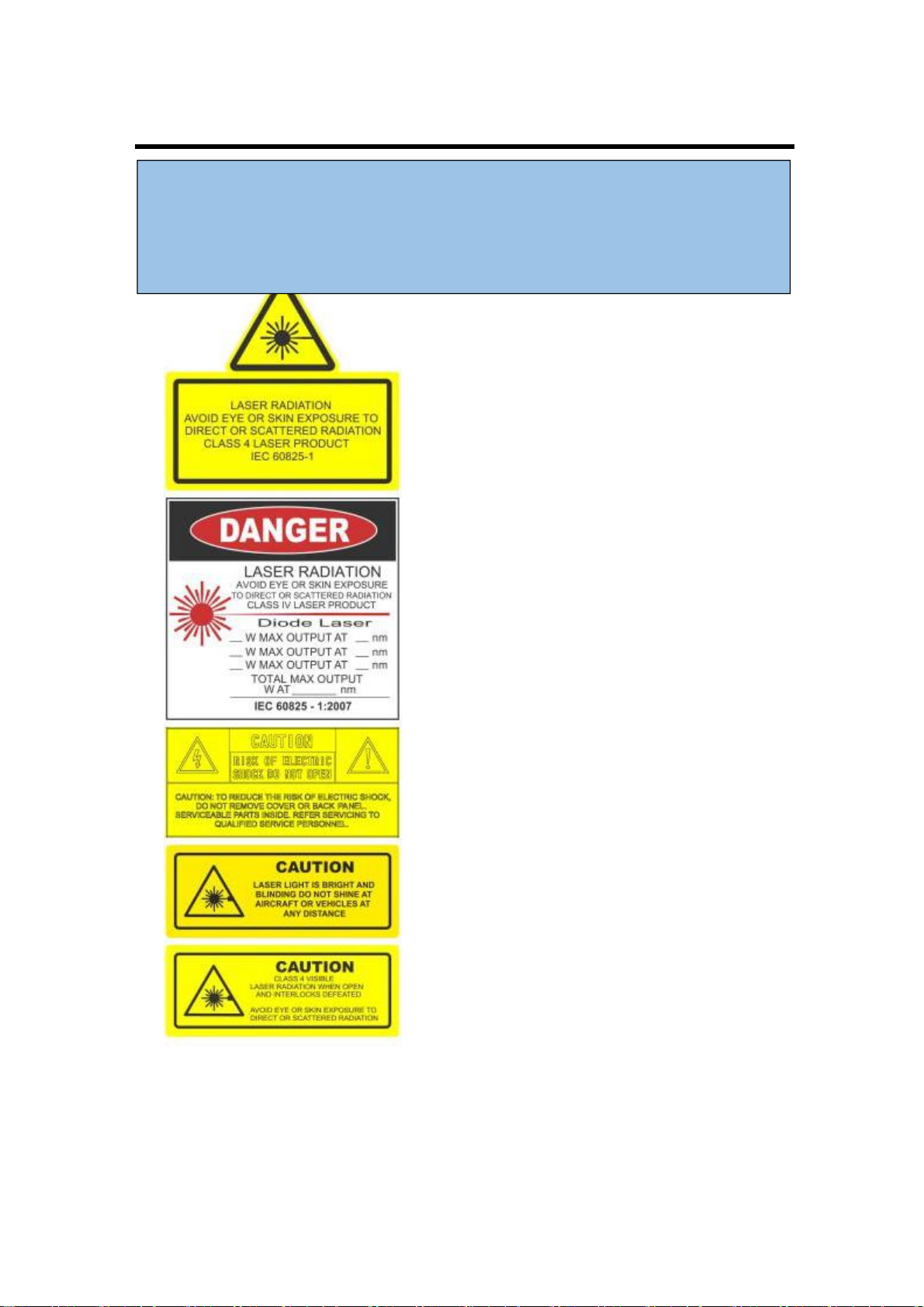
laser. 1W of quality laser light is very powerful and although it doesn’t sound like much it can
burn eye retinas, skin and clothes or even start a fire!
What makes the laser visible?
Mainly it is the particles of dust in the air that the laser beam hits on its path. That’s why we
“laserists” use haze or smoke machines to make lasers more visible. Too much of the haze or
smoke will kill it, but the right amount will make all the difference between no show and a
great show.When outdoors, lasers mainly reflect off dust and mist in the air but due to
unpredictable wind conditions we can never make sure the hazers or smoke machines will be
effective enough. And that ’s why we use high power lasers for outdoor shows –to
substitute for the lack of dust, haze and smoke.
How far does it go?
Depending on the power output of the system and weather conditions, the laser can be visible
for miles –that is why we need to be cautious about aircrafts when performing outdoor shows.
And if you get a system that is powerful enough then yes, it can reach the Moon.
Colours
Standard full colour analogue lasers use three primary colours: Red, Green and Blue. By
mixing those together you can pretty much get any secondary colour:
Of course the number and precision of the colours is determined by the modulation, stability and
linearity of the system. If the system is not stable enough, it will produce different colours every
time it is used,making it virtually impossible to match the colours of two systems at any one time.
This is very often the case with systems from far east manufacturers and with re-branded lasers
that are being presented as European makes.
Scanning System
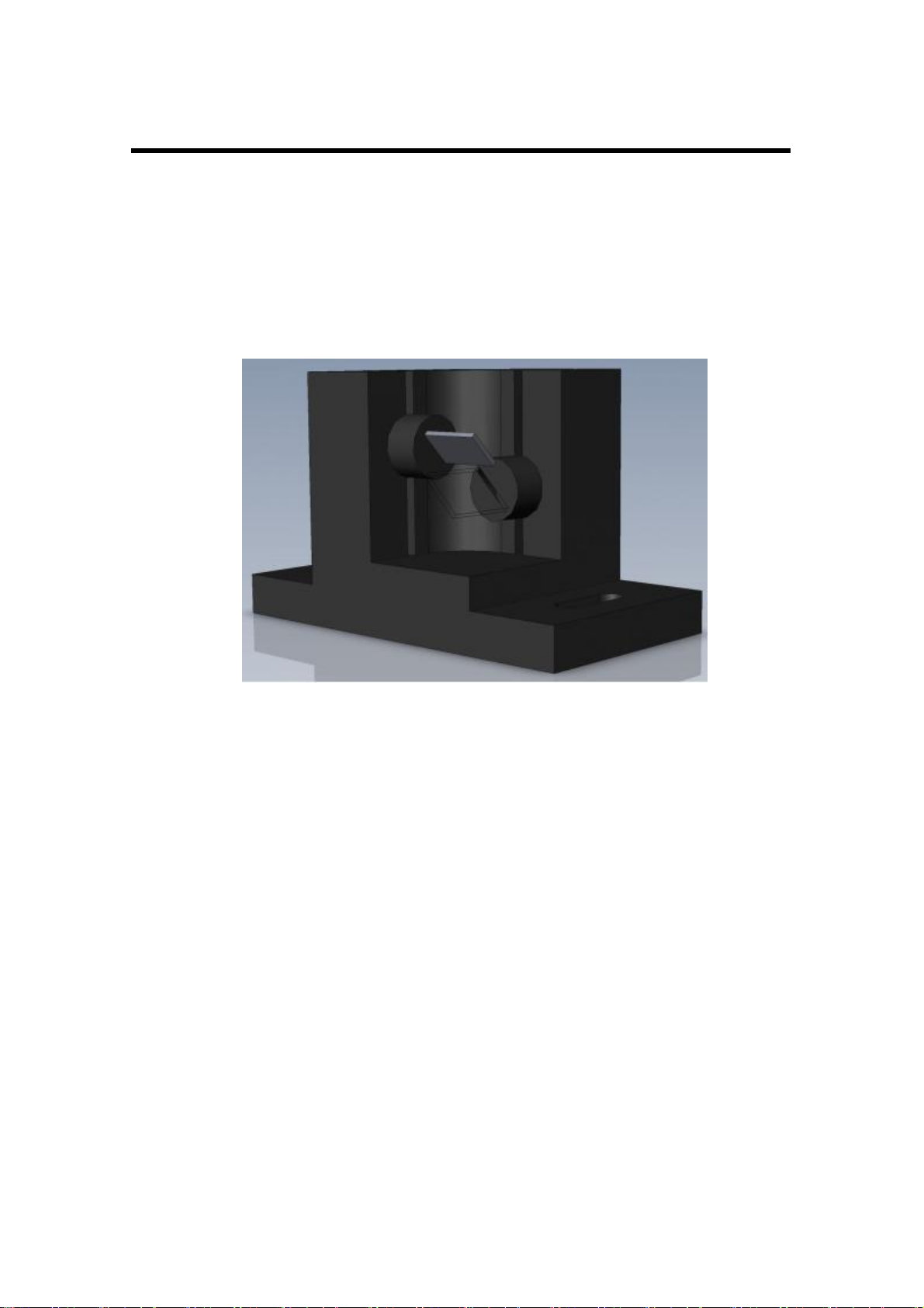
A scanning system is essentially two tiny mirrors, each moving on X or Y axis. By working
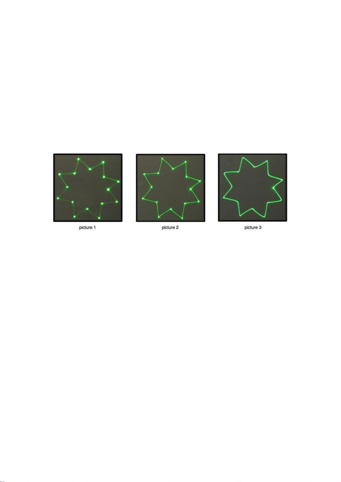
together they can “scan” the laser beam in all directions. Once a shape is scanned more than
20 times per second, it appears static to the human eye. So any shape drawn by a laser is
actually produced by one single laser beam running around like crazy. Every scanning system
has a mechanical limit of how fast it can move its mirrors and therefore how many points it
can display at any one second and that is usually represented in Points Per Second at a certain
scanning angle, i.e. 8 degrees.

第5页
!Any laser system classified as a Class 4 laser must be used with caution. If you are not
an experienced laser operator we would strongly recommend that you attend a laser
display safety course as soon as possible, and ideally before this laser system is used in
pubic areas. There are various places in Europe where you can attend quality training
and even a one day course will give you a good amount of valuable information to safely
start with.
!Before proceeding any further, please read the following safety page very carefully. It
could help you avoid dangerous and hazardous situations which could lead to serious
injury or property damage.
Laser Safety First!
Unless you are very competent with the use of lasers and about the laser safety, make sure
you follow these basic laser safety rules:
1: Never look directly into a laser beam.
2: Never look directly into laser aperture if the laser system is switched on.
3: Be aware that lasers can burn the eye retina, skin or cause fires if not used correctly.
4: Never perform Audience Scanning – that’s when laser beams and effects hit an audience
directly. Always project with the laser above audience head level – at least 3m above floor
level.
5: When performing outdoors, avoid pointing the laser at aircrafts, buses, trains, etc.
6: Never leave the laser system unattended when it’s switched on.
7: Always check for reflective surfaces within the laser range – these can be very dangerous
(i.e. mirror behind the bar in a club could bounce the beam into bar attendant’s eye).
8: Never hesitate to use the Emergency STOP if you think there’s a fault within the laser
system or a potential danger to a person/object caused by the laser performance.

第6页
Installation of the System
Please follow these rules during the installation:
1: Do not connect the device to power supply during the installation.
2: Mount the system only to mounting point that is strong, secure and away from places
where non-authorised person could get an access to.
3:Always make sure the system is properly tighten down and that it cannot get loose and
move as a result of sound vibrations, cable pull or similar.
4: Always use a safety rope.
5: Ensure that all the cables have enough leverage just in case they get caught.
6: Ensure that the system is placed at least 20cm away from walls or any other objects
including drapes etc.
7: Ensure that the system is placed well away from any heat sources including spotlights,
moving heads, radiators, etc. Make sure there is a sufficient air-flow around the laser system.
8: It is essential that the fan openings are never covered during the laser operation.
9: Always follow the Laser Safety Regulations of respective country where the laser is being
used.
Control System
The overall performance of any our laser system is also dependent on the control system that
you use for operating the laser as well as the correct device configuration in the laser control
software.There are many laser control options on the market but we mainly recommend
control systems from these two manufacturers:
Pangolin Laser Systems
Showtacle
!The manufacturer is not liable for damages or a injury caused by improper installation
of the system.
The installation should be carried by a qualified installer who should follow the Laser
Safety Regulations of respective country.

第7页
Scanning System
The product warranty does not cover the damages to the scanning system caused by improper
use of the scanning system or by incorrect programming. Therefore it is essential to
understand how the scanning works and where are the limits of it. In this manual we will
explain only the basics of it but it is the responsibility of every user to educate themselves so
they can avoid damage being caused to the scanning system and costly repairs.
A laser beam comes from a laser module and hits the two moving mirrors of the scanning
system. These mirrors are mounted on the scanner shafts and are moved by the scanner rotors,
one on X and one on Y axis.
An effect such as tunnel (circle) is displayed by a repetitive mechanical movement of the scanners.
For each scanning system and effect, there’s a maximal scan rate that is defined by mechanical
load, scanner mirror size and weight, complexity of displayed picture and size of the projection
(an angle under the laser beam is being projected). A different scanning systems have different
scan- rate limits. It is essential to operate the scanning system at scan-rates within its maximal
limit at all times to prevent it from overload damage.
How to establish correct Scan-rate and maximal number of points in an effect
Each effect (picture) contains a different number of graphical points which defines the actual
shape of the effect. The more points an effect contains, the lower the maximum scan rate will be
in relation to the scanning angle.
As an example we ’ll work with the star effect shown below and with the parameters of
quality scanning system:
Let ’s say the star effect is made of 300 graphical points (including non-visible blanking
points) and we know that the maximal scan-rate of our scanning system is 35kpps @ 8
degrees (= 35.000 points per second at 8 degrees projection angle). We also know that we
display the star 35 times per second which is a default frame rate of the control software we
are using.

第8页
So we need to display 300 points 35 times per second = 10.500 pps. This means that we could
display 3of these stars beside each other within one single laser effect and that it would be
quite close to the scanner limit (3 ×10.500 = 31.500pps). This however applies than 8
degrees on both axes! If we start to increase the size of the projection (scanning angle) it is
necessary to either lower the number of points within the effect or drop down the scan-rate in
the control software (FPS) to a safe level –which may result in flicker.
From the example above we can also determine how many points this scanning system is able
to project if the scanning angle is not more than 8 degrees:
35.000 points / 35 Frames Per Second = 1.000 pps. This is the absolute maximum of how
many points we should be using when programming an effect if the scanning angle is not
more than 8 degrees.
In the following pictures you see the same star effect scanned at different scan rates at full
scanning angle (60 degrees).
Picture 1: the scan rate and/or number of points is too low. The corner points are more visible
than the lines between them and the whole effect flickers. The scan-rate and/or number of
points needs to be increased.
Picture 2: the scan-rate and/or number of points is about right. The whole effect has more or less
the same intensity and does not flicker.
Picture 3: further increasing of the scan-rate and/or number of points results in the effect
starting to distort, firstly around corners only. This indicates that you are exceeding the maximal
scan rate of the scanning system! If you operate the scanning system at scan-rates higher than
the maximum scan-rate of the scanning system the scanners will get damaged irreversibly due to
overheated coils damaging rotor magnets.

第9页
!USA ONLY : Interlock Connector must be inserted in the E-order to
disable the interlock.
.
*Both E-STOP Remote safety key and laser system safety key must be inserted
and switched to ON position in order to disable the interlock.
Connection Diagram
Please check that all the signal and power leads are correctly installed and that the safety keys
are inserted in all necessary positions.
Basic connection diagram

第10 页
Power Connections Method
Please connect power as following :
L(live wire )=brown wire
E
(earth wire)
=yellow/green double color wire N
(null line )=blue wire
When connecting,ensure that the voltage and frequency of power supply match the
power requirement of the product.
This product is Class 1 protection equipment.The yellow-green double colors wire
must be earthed by qualified personnel. Before installation,ensure that the voltage and
frequency of power supply match the power requirements of product.In power supply
and voltage fluctuation large areas,we suggest you to use 110V or 220V or use
voltage regulator to supply power.After electrical connection,this product will have a
few seconds self-check action, self-check finished can be used.
Important:It is essential that Yellow/green double color wire is correctly earthed
and that electrical installation conforms to all relevant standards
DMX Connection method
DMX control signal connection must be made with a two core-screened cable,with
each core having at least a 0.5mm diameter.Please use the product's signal cable OUT
and IN as connection.The signal OUT and IN cables connection shown as above
picture.
Note:Please do not connect the signal cable OUT and IN in other way except above
shown.

第11 页
This product accepts digital control signals in protocol DMX512(1990).The
amount of lighting fixtures connected in parallel is no more than 32.Connect the
DMX controller's Output to the first lighting fixture's Input cable with a 2 core XLR
signal cable(Shown as above ),connect the first lighting fixture's Output cable to the
second lighting fixture's Input cable and connect the rest light fixtures in the same
way.Eventually,connect the last lighting fixture's Output cable to a DMXterminator
Under DMX-512 signal control mode,the last lighting fixture's DMX Output must be
connected with a DMX terminator.This prevents electrical noise from disturbing and
corrupting the DMX control signals.The DMX terminator is simply an XLR
connector with a 120Ω(ohm) resistor connected across pins 2 and 3,which is then
plugged into the output socket on the last projector in the chain.Then connections are
illustrated above.
ILDA control signal connection method:
Connection built through product male/female DB 25 degree socket.Like above
picture. In addition to the above connections, ILDA signal cannot be connected in any
other way

第12 页
LCD Menu and function introduction
*Main panel displays:
Version: Software version;
DMX Address: DMX address code;
Mode: Current working mode;
File: The current working file;
1. In the main panel, click the button to enter the menu.
2. In the main panel, ILD and PRG mode, double-click the button to change the folder.
3. After entering the menu, you can double-click the button to exit.
*LCD setting of menu:
NO.
First-grade menu
Menu
description
Setting item
Setting
instructions
Note
1
DMX Address
DMX address
setting
1-512
DMX address
value
2
Show Mode
Play mode
ILD
ILD program
single loop
playback
Automatically switch to
DMX mode when
connected to DMX
PRG
Play according
to PRG list
order
Auto
Self-propelled
mode
Sound
Voice control
mode
3
Program
Select a self-
propelled
program
progr0
Program 0
Programs 1 to 3 need to
be edited with the
console and imported
progr1
Program 1
progr2
Show 2
progr3
Program 3
progr4
Program 4
4
SD FILE
Folder inside SD
card
Folder name
The currently
selected folder
name
Only valid when
playing SD card
5
Size
Graphic size
10-100
Percentage of
the currently set
graphic size
6
Phasic
Direction of
built-in shows
X+ Y+
Built-in
program phase
Only valid for built-in
graphics
7
Speed
Play speed
8-40
Speed of built-
in shows
Set according to the
galvanometer

第13 页
8
DMX State
State without
DMX signal
Show
Set playback
according to
Show Mode
Black
No light
9
Slave Mode
Master-slave
status
Slave
Slave
Set to Slave state when
not connected
Master
Host
10
Y Phasic
Y direction
Positive
positive
Valid for signals from
this unit and ILDA
Reverse
anti-
11
X Phasic
X direction
Positive
positive
Reverse
anti-
12
Color Mode
Color mode
RGB
color
White
monochrome
13
Laser Lock
Laser light lock
ON
open
Closed laser protection
when the laser angle is
too small
OFF
turn off
14
Sound sense
Voice control
sensitivity
0-100
Voice control
sensitivity
percentage
15
SD Sound
Animation
content voice
control switch
ON
open
OFF
turn off
16
Highlight
Brightness
setting
0-100
Highlight
setting
percentage
Set as a highlight at the
color junction
17
ILDA Lock
ILDA mode
lock
ON
Locked as input
signal from
ILDA
Select lock to switch to
ILDA input when using
RJ45 interface
OFF
Not locked
18
Load Flash
Load FLASH
ON
Import ILD
programs from
SD card
Import programs from
the SD card's <LOAD>
folder
OFF
19
Update Prog
Update built-in
shows
OFF
Don't update
Import shows from
show1.yuq-show4.yuq
progr1
Update show 1
progr2
Update 2
progr3
Update 3
progr4
Update 4
all
Update
Program 1-
Program 4

第14 页
*DMX-512 Channel function
Channel
Function
Value
Description
CH1
Mode selection
0-5
Closed light
6-49
Automatic mode
50-99
Voice control mode
100-149
PRG file sequential playback
150-199
ILD file loop playback
200-255
Manual mode
CH2
Graphics /
folder selection
0-255
Manual mode
PRG and ILD modes
Graphic selection, one
graphic for every three
values
Folder selection
CH3
Strobe / Play
file
0-10
No strobe
Play file selection
11-199
Automatic strobe speed
from slow to fast
200-255
Voice-activated strobe
CH4
Selection of
color
0-16
white
0-10
ILD file
primary
colors
11-16
white
17-33
red
34-50
green
51-67
blue
68-84
yellow
85-101
purple
102-118
blue
119-135
White, red, green, and blue color segments
136-152
Blue, yellow, purple and cyan color segments
153-169
White red green blue yellow purple green color
segmentation
170-186
White, red, green, blue colors flowing
187-203
Blue, yellow, purple, and cyan colors flow
204-220
White red green blue yellow purple cyan color
flow
221-237
Color breaks based on graphic breakpoints
238-255
Voice-controlled color change
CH5
Display mode
0-63
normal display
64-127
Highlight display
128-191
Segmented display
192-255
Point display
0-63
normal display
CH6
X move
0-125
Adjust the position manually
126-185
Automatic left and right circular motion
186-225
Automatic jump left and right circular movement

第15 页
226-245
Automatic irregular jumping
246-255
Voice-controlled irregular jump
CH7
Y move
0-125
Adjust the position manually
126-185
Automatic up and down cycle movement
186-225
Auto jump up and down cyclic movement
226-245
Automatic irregular jumping
246-255
Voice-controlled irregular jump
CH8
Zoom
0-10
No scaling
11-87
Resize manually
88-150
amplification
151-200
Zoom out
201-255
Loop zoom
CH9
X rotation
0
No rotation
1-128
Manual adjustment
129-255
Automatic rotation
CH10
Y rotation
0
No rotation
1-128
Manual adjustment
129-255
Automatic rotation
CH11
Center rotation
0
No rotation
1-128
Manual adjustment
129-192
Automatic clockwise rotation
193-255
Automatic counterclockwise rotation
CH12
Gradual
painting
0-10
No fade
10-74
Adjust the fader manually
75-104
Auto-grading (increase)
105-144
Automatic fade (minus)
145-184
Automatic loop fade
185-224
End-to-end loop drawing gradually (increase)
225-255
End-to-end loop gradual drawing (minus)
CH13
X wave
0-9
No waves
10-69
Small amplitude wave
70-129
Medium amplitude wave
130-189
Large wave
190-255
Maximum amplitude wave
CH14
Y wave
0-9
No waves
10-69
Small amplitude wave
70-129
Medium amplitude wave
130-189
Large wave
190-255
Maximum amplitude wave
CH15
Red modulation
0-255
Red light from brightest to dark
CH16
Green
modulation
0-255
Green light from brightest to dark
CH17
Blue
modulation
0-255
Blue light from brightest to dark

第16 页
Product technical parameters
1.Voltage:AC90~240V 50~60HZ±10%
2.Power consumption:120W
3.Laser source: diode.
4.Laser power /wavelength:
1x1000mW Red(638nm)
1x1000mW Green (520nm )
1 x 2000mW Blue (445nm )
5.Beam size: 4mm at aperture
6.Divergence: <1.0mrad-full angle
7.Colors:RGB full color
8.External Modulation:Analog
9.DMX Channel:17CH
10.Scanner system: 30kpps
11.Control signal:DMX-512 international standard signal
12.Control mode:Music,auto,master-slave and DMX-512,ILDA Control
13.Cooling system:fan
14.Operation environment :Indoor
15.Operation temperature:-10°C~40°C
16.Net Weight :3.5kg
17.Dimension Size : 27(L)*15(W)*13(H)cm

第17 页
Maintenance
To prolong the life of the product, it is very important to do maintenance work.
The environment is hash outdoors, or if the product is idle for a long time, damp,
smoke or particularly dirty surroundings can cause greater accumulation of dirt
on its cover and housing. So it should be cleaned to maintain an optimum light
output and at the same time to prevent it from corrupted by acid gas.
Cleaning frequency depends on the environment in which the fixture
operates. Soft cloth and typical glass cleaning products should be used for
cleaning. It is recommended to clean product at least once every 20 days.
Friendly notice: Do not use any organic solvent, e.g. alcohol to clean housing
of the apparatus.
Troubleshooting
Problems
Action
Power connection is not correct. Re-connect the power.
The product doesn't
Power supply is damaged or abnormal. Call a qualified personnel to fix it.
switch on
Connection of control board is not correct. Call a qualified personnel to
fix it.
The product can turn
Control mode is wrongly setting up. Resetting it according to instruction
book
on, but no light coming
Control section is damaged. Call a qualified personnel to fix it.
out.
The beam appears dim
The product is too hot. Take ventilation measures to make it cool.
Note:This product is under warranty for 1 year(From the date of delivery), 1
years after can provide paid maintenance services. But if it is because of natural
disasters or user's operation not according to manual. We won't provide
warranty.
This manual suits for next models
1
Table of contents
Other gagalight Lighting Equipment manuals
Popular Lighting Equipment manuals by other brands

MELINERA
MELINERA 304960 Operation and safety notes

Vision & Control
Vision & Control DL30x30-B470/UDC/-a Instructions for use

KSIX
KSIX HALO BXPLAFLED02 user manual

thomann
thomann STARVILLE PAR56 10MM UV LED-PAR user manual

Festive Lights
Festive Lights SL066 quick start guide

Haushalt International
Haushalt International 70282 Directions for Use and Care