SECTION ONE
Important
Information
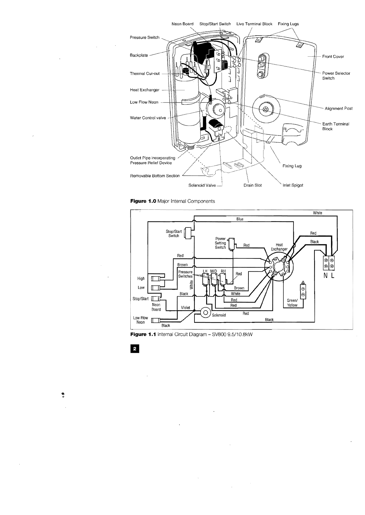
Your shower
is
designed and tested to the
very highest standards and complies fully
with
all
of
the
relevant national/intemational
standards for safety and reliability.
The shower
is
manufactured
in
a
BS
EN
ISO 9002-registered factory your
assurance
of
a quality product.
To
ensure correct use and maintenance
of
the shower, please read and adhere
to
the
following warnings and guidelines.
For
Installers:
1.1
Do not attempt any of the electrical
or
plumbing
work
necessary to install this
product unless you have
good
practical
experience and adequate understanding
of
the lEE Wiring Regulations and Water Bye-
Laws.
1.2
WARNING: THIS APPLIANCE
MUST
BE EARTHED.
1.3
Before removing your shower heater
cover always ensure your shower heater is
isolated from the electrical mains.
1.4
This product is splash-proof, and is
approved for use
in
shower cubicles and
over baths. However,
do
not install the
shower heater
in
a position where
the
handset,
in
its normally-parked position, will
consistently direct spray over it.
1.Sa
We strongly recommend that you fit
an
isolating valve
in
the pipework
to
the
shower,
in
an
accessible place. This will
be
of great benefit if any maintenance work,
or
complete replacement
of
the shower, is
required later on.
1.Sb This shower
is
designed for domestic
use and
is
not vandal-resistant.
If
it
is
installed
in
an
institutional
or
commercial situation,
frequent inspection may
be
necessary, and
our guarantee may
be
affected.
a
For
Users:
1.5
If water emerges from anywhere other
than the spray head outlets,
do
not use your
shower, and refer to the fault-finding section.
1.6
IT
IS
IMPORTANT TO CLEAN
THE
HANDSET SPRAY PLATE
REGULARLY, particularly
in
hard water
areas, where this may
be
necessary as
often as
once
a week. Failure to
do
so will
affect the performance
of
the shower, and
in
extreme cases may cause the pressure
relief device
to
operate.
Refer
to
Section
6.
1.7
The
shower
heater
outlet,
hose
and
handset
act
as
a
vent.
They
must
not
be
blocked, obstructed,
or
have
connected
to
them
any
fitting
not
approved by us. The use
of
unapproved accessories may invalidate the
guarantee and affect the performance and
safety
of
the unit.
1.8
WARNING: DO NOT USE the shower
if the HOSE
IS
DAMAGED
in
any way; for
instance if the outer covering has parted to
reveal the inner tube. A damaged hose can
suddenly restrict the flow and result
in
extremely hot water from the spray head.
A damaged hose could completely block
the outlet
of
the
shower; the resulting
increase
in
pressure could burst a
weakened
or
damaged hose.
1.9
Do not install the shower
in
a situation
where the water
in
it could freeze. Any
damage caused
by
freezing will
not
be
covered
by
the guarantee.
If
you
suspect
your
shower
is
frozen, SWITCH OFF IMMEDIATELY.
Refer
to
Fault-Finding, Section Five.
1.10
Do not leave young children, the infirm
or the disabled unattended
in
the shower.
1.11
Before stepping into the shower,
always test the temperature of
the
spray
with your hand.
1.12
Switch off at the isolating switch
after use. This is a safety procedure
recommended with
ALL
electric appliances.