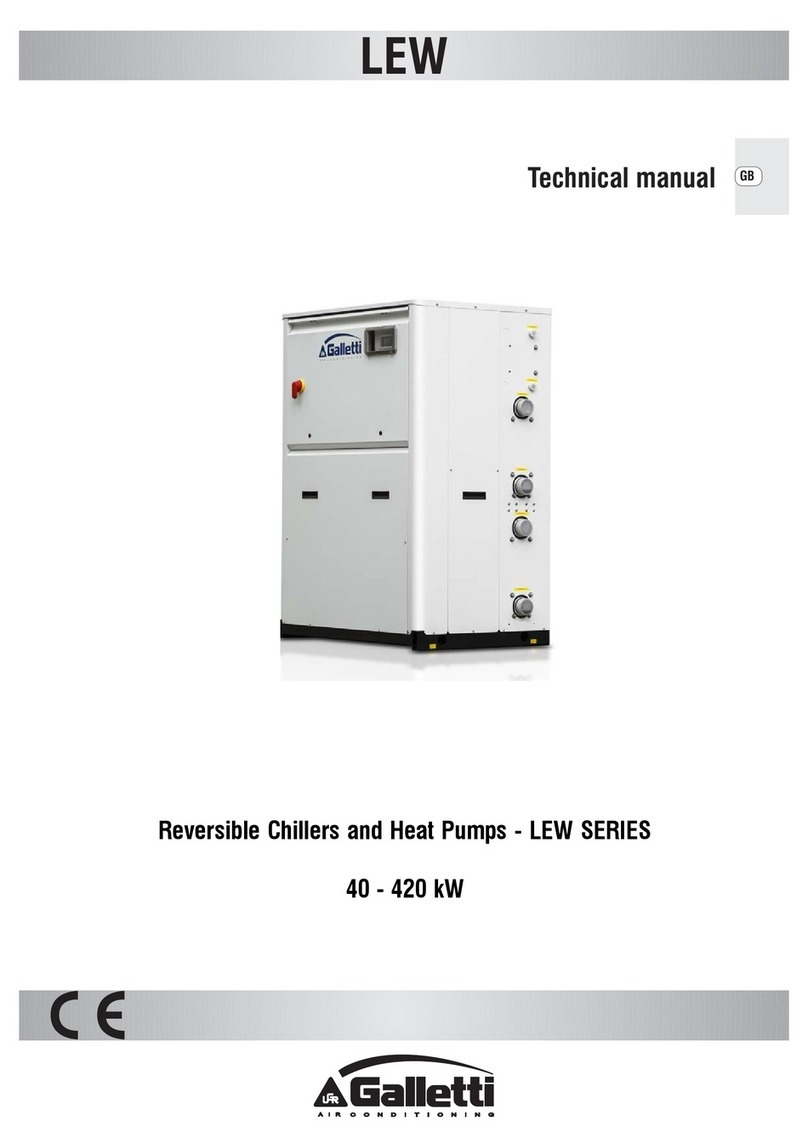
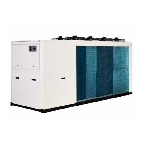
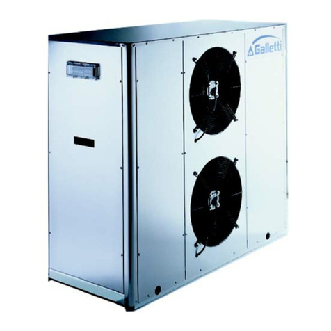
Galletti LCA Series Quick start guide

GB
Installation, use and maintenance

LCA
RG66000986 – Rev.00 2
TABLE OF CONTENTS
TECHNICAL DATA Ref. Rating Plate
THE SERIES
FIELD OF APPLICATION
GENERALITIES
INSPECTION, CONVEYANCE, SITING
Inspection
Lifting and conveyance
Unpacking
Siting
INSTALLATION
Installation clearance requirements
General guidelines for plumbing connections
Water connection to the evaporator
Safety valve drain pipes
Electrical connections
Generalities
Electrical connections of differential pressure switch/flow switch
Electrical connections of circulation pump
Remote controls
STARTING UP
Preliminary checks
Starting operation
Checks during operation
Checking the refrigerant level
Stopping the unit

LCA
RG66000986 – Rev.00
3
TABLE OF CONTENTS
OPERATING LIMITS
Water flow to evaporator
Chilled water temperatures
Outdoor air temperature
Operation with water at low temperatures
CONTROL DEVICE SETTINGS
Generalities
Maximum pressure switch
Minimum pressure switch
Service thermostat
Anti-freeze thermostat
Anti-recycle timer
Oil differential pressure switch
ROUTINE MAINTENANCE AND CHECKS
Warnings
Generalities
Repairing the cooling circuit
Tightness test
Hard vacuum and drying of cooling circuit
Charging with R407C refrigerant
Environmental protection
RETIRING THE UNIT
TROUBLESHOOTING
DRAWINGS SHOWING OVERALL DIMENSIONS
WATER PRESSURE DROPS

LCA
RG66000986 – Rev.00 4

LCA
RG66000986 – Rev.00
5
THE SERIES
The LCA series of chillers with fluid heat pumps covers a power range from 44.8 to 234 kW.
FIELD OF APPLICATION
These machines are designed to cool-heat water and solutions containing up to 30% glycol (percentage
by weight) in civil, industrial and technological air-conditioning systems.
They must be used in observance of the operating limits specified in this manual; failure to comply with
said limits will invalidate the warranties provided in the contract of sale.
GENERALITIES
- When installing or servicing the chiller, you must strictly follow the rules provided in this manual,
comply with the directions on the units and take all such precautions as are necessary.
- The fluids under pressure in the cooling circuit and the presence of electrical components may cause
hazardous situations during installation and maintenance work.
Therefore, only qualified personnel may perform any kind of work on the unit.
- Failure to comply with the rules provided in this manual or any modification made to the unit without
prior authorisation will result in the immediate invalidation of the warranty.
Warning: Before performing any kind of work on the unit, make sure it has
been disconnected from the power supply.
Declaration of conformity
Galletti S.p.A., whose main office is at n°12/a Via Romagnoli, 40010 Bentivoglio (BO) - Italy, hereb
y
declares, under its sole responsibility, that the LCA water chillers, devices for air conditioning systems,
conform to the specifications of EEC Directives 73/23, 89/392, 91/368, 93/44, 93/68, 97/23, 89/336.
Bologna, 22/01/2002 Luigi Galletti
President

LCA
RG66000986 – Rev.00 6
INSPECTION, CONVEYANCE, SITING
INSPECTION
On receiving the unit, check that it is perfectly intact: the machine left the factory in perfect conditions;
immediately report any signs of damage to the carrier and note them on the Delivery Slip before signing
it.
Galletti S.p.A. or its Agent must be promptly notified of the entity of the damage.
The Customer must submit a written report describing every significant sign of damage.
LIFTING AND CONVEYANCE
While the unit is being unloaded and positioned, utmost care must be taken to avoid abrupt or violent
manoeuvres. The unit must be handled carefully and gently: avoid using machine components as
anchorages when lifting or moving it.
The unit must be lifted using steel pipes inserted through the eyebolts provided on the base frame.
Prior to being lifted, the unit should be harnessed as shown in the figure below: use ropes or belts of
adequate length and spacer bars to avoid damaging the sides and top of the unit.
Warning: In all lifting operations make sure that the unit is securely anchored
in order to prevent accidental falls or overturning.
UNPACKING
The packing must be carefully removed to avoid the risk of damaging the unit. Different packing
materials are used: wood, cardboard, nylon etc.
It is recommended to keep them separately and deliver them to suitable waste disposal or recycling
facilities in order to minimise their environmental impact.
SITING
You should bear in mind the following aspects when choosing the best site for installing the unit and the
relative connections:
- size and origin of water pipes;
- location of power supply;
- accessibility for maintenance or repairs;
- solidity of the supporting surface;
- ventilation of the air-cooled condenser and necessary clearance;
- direction of prevalent winds: avoid positioning the unit in such a way that the prevalent winds favour
the backflow of air to the condenser coils; a speed of 8 m/s (28.8 km/h) already generates a sufficient
stagnation pressure to guarantee 60% of the nominal air flow rate.[In situations where the action of air
currents is inevitable and there is a simultaneous presence of temperatures below – 5°C, the control of
condensation for low outdoor temperatures must be of the flooding type or with a device for choking
the condensing exchanger -contact the technical department for further details]
- possible reverberation of sound waves.
All models belonging to the LCA series are designed and built for outdoor installation: avoid covering
them with roof structures or positioning them near plants (even if they only partly cover the unit) which
may interfere with the regular ventilation of the unit condenser.
It is a good idea to create a base of adequate dimensions to support the unit. This precaution becomes
essential when the unit is to be sited on unstable ground (various types of soil, gardens, etc.).
LCA
RG66000986 – Rev.00
7
It is advisable to place a rigid rubber strip between the base frame and the supporting surface.
Whenever more effective insulation is required, it is recommended to use vibrating-damping spring
supports.
In the case of installation on roofs or intermediate storeys, the unit and pipes must be insulated from
walls and ceilings by placing rigid rubber joints in between and using supports that are not rigidly
anchored to the walls.
If the unit is to be installed in proximity to private offices, bedrooms or areas where noise levels must be
kept down, it is advisable to conduct a thorough analysis of the sound field generated and verify its
compatibility with the local laws in force.

LCA
RG66000986 – Rev.00 8
INSTALLATION
INSTALLATION CLEARANCE REQUIREMENTS
It is of fundamental importance to ensure an adequate volume of air both on the intake and outlet sides
of the condenser coils; it is highly important to prevent the air delivered from being re-aspirated as this
may impair the performance of the unit or even cause an interruption in normal operation. For this
reason it is necessary to guarantee the following clearances (see figure on this page):
- rear side/plumbing connections: min. 1.5 metres to guarantee access to plumbing connections and/or
for any necessary maintenance on the pumps, reservoir, expansion tank and flow switch.
- electric control board side: min. 1.5 metres to guarantee access for inspection and/or maintenance of
cooling components
- coil side: min. 1.5 metres to ensure proper air circulation and access to the compressor compartment,
also from the side.
- top side: there must be no obstacle to expulsion.
1.5 m
1.5 m 1.5 m
1.5 m

LCA
RG66000986 – Rev.00
9
GENERAL GUIDELINES FOR PLUMBING CONNECTIONS
When you are getting ready to set up the water circuit for the evaporator you should follow the
directions below and in any case make sure you comply with national or local regulations (use the
diagrams included in this manual as your reference).
- Connect the pipes to the chiller using flexible couplings to prevent the transmission of vibrations and
to compensate thermal expansions.
- It is recommended to install the following components on the pipes:
•temperature and pressure indicators for routine maintenance and monitoring of the unit. Checking
the pressure on the water side will enable you to verify whether the expansion tank is working
efficiently and to promptly detect any water leaks within the equipment.
•traps on incoming and outgoing pipes for temperature measurements, which can provide a direct
reading of the operating temperatures. Temperature readings can in any case be obtained from the
microprocessor installed on the unit.
•regulating valves (gate valves) for isolating the unit from the water circuit.
•metal mesh filter (incoming pipes), with a mesh not to exceed 1 mm, to protect the exchanger from
scale or impurities present in the pipes.
•air vent valves, to be placed at the highest points of the water circuit for the purpose of bleeding
air. [The internal pipes of the unit are fitted with small air vent valves for bleeding the unit itself:
this operation may only be carried out when the unit is disconnected from the power
supply]
•drainage valve and, where necessary, a drainage tank for emptying out the equipment for
maintenance purposes or when the unit is taken out of service at the end of the season. [A 1”
drainage valve is provided on the optional water storage reservoir: this operation may only be
carried out when the unit is disconnected from the power supply]
WATER CONNECTION TO THE EVAPORATOR
It is of fundamental importance that the incoming water supply is hooked up to the
connection marked “Water Inlet”
Otherwise the evaporator would be exposed to the risk of freezing since the antifreeze thermostat would
not be able to perform its function; moreover the reverse cycle would not be respected in the cooling
mode, resulting in additional risks of malfunctioning
The dimensions and position of plumbing connections are shown in the dimension tables at the back of
the manual.
The water circuit must be set up in such a way as to guarantee that the nominal flow
rate of the water supplied to the evaporator remains constant (+/- 15%) in all operating
conditions.

LCA
RG66000986 – Rev.00 10
The compressors often work intermittently, since the chilling requirements of the user generally do not
coincide with the compressor output. In systems containing little water, where the thermal inertia of the
water itself is lower, it is a good idea to check that the water content in the section delivering to users
satisfies the condition below:
V = water content in user section [m3]
Sh = specific heat of the fluid [J/(kg/°C)]
ρ= fluid density [kg/m3]
Dτ= minimum time lapse between 2 compressor restarts [s]
DT = allowed water T differential [°C]
Cc = Cooling capacity [W]
Ns = N° of choking steps
Tank
Ts
Q; TW in Q; TW out

LCA
RG66000986 – Rev.00
11
A standard feature of LCA units is a device for controlling the flow rate (flow switch or
differential pressure switch) in the water circuit in the immediate vicinity of the
evaporator. Frame 3, 4, 5 units include a blade-type flow switch positioned in the
ventilation compartment.
Any tampering with said device will immediately invalidate the warranty.
It is advisable to install a metal mesh filter on the inlet water pipe.
It is strongly recommended to install a safety valve in the water circuit. In the event of
serious equipment faults (e.g. fire) it will enable water to be drained from the system,
thereby preventing possible bursts. Always connect the drain outlet to a pipe with a
diameter at least as large as that of the valve opening and direct it toward an area
where the discharge of water cannot harm people. This is a standard feature of units
equipped with the optional storage reservoir.
Warning: When making the plumbing connections, make sure there are no open flames
in proximity to or inside the unit.
SAFETY VALVE DRAIN PIPES
Safety valves are fitted in each refrigerant circuit: some regulations provide that the refrigerant drained
from the valves be conveyed to the outside by means of a suitable pipe with a diameter at least
matching that of the valve drainage outlet; the valve must not be made to bear the weight of the pipe.
The valves positioned on the compressor outlet only discharge hot saturated gas; those on the liquid
receivers, despite being positioned in the top part of the latter, may discharge saturated liquid and pose a
greater hazard of burns due to the strong dehydrating effect caused by the sudden evaporation of
refrigerant fluid in contact with bodies having a T > -41 °C.
Warning: Always direct the drain pipe toward an area where the discharge cannot harm
people.

LCA
RG66000986 – Rev.00 12
ELECTRICAL CONNECTIONS
GENERALITIES
Before carrying out any job on electrical parts, make sure the power supply is
disconnected.
Check that the mains electricity supply is compatible with the specifications (voltage, number of phases,
frequency) shown on the unit rating plate.
The connection to the power supply should be made with a three-pole + neutral cable and earthing wire.
The size of the cable and line protections must conform to the specifications provided in
the wiring diagram.
The supply voltage may not undergo fluctuations exceeding ±5% and the unbalance between phases
must always be below 2%.
The above operating conditions must always be complied with: failure to ensure said
conditions will result in the immediate invalidation of the warranty.
The electrical connections must be made in accordance with the information shown in the wiring diagram
provided with the unit and current regulations.
An earth connection is required by law. The installer must connect the earthing wire using the earthing
terminal situated on the electric control board (yellow and green wire).
The power supply to the control circuit is shunted from the power line through an insulating transformer
situated on the electric control board.
The control circuit is protected by suitable fuses.

LCA
RG66000986 – Rev.00
13
ELECTRIC CONNECTIONS OF FLOW SWITCH OR DIFFERENTIAL WATER PRESSURE SWITCH
It is pre-wired in all LCA units. Frame 1, 2, 3 units feature a differential pressure switch that detects
pressure drops upstream and downstream from the evaporator (outgoing – returning water in the case
of units equipped with a pump system) ; Frame 4, 5 units have a blade-type flow switch installed in
series with water circuit.
ELECTRIC CONNECTIONS OF THE CIRCULATION PUMP
If selected on ordering, it/they is/are supplied pre-wired with all LCA units.
The pump must be started before the chiller and stopped after the latter (minimum
recommended delay: 60 seconds). If included as an option, this function is already
performed by the electric control board on the unit.
REMOTE CONTROLS
If you wish to include a remote control for switching the unit on and off, you must remove the bridge
between the contacts indicated in the wiring diagram and connect the remote ON/OFF control to the
terminals themselves [see annexed wiring diagram].
All remote controls work with a very low voltage (24 Vac) supplied by the insulating
transformer on the electric control board.
REMOTE SUMMER-WINTER SWITCHING
If you wish to include a remote control for switching the unit between the summer and winter operating
modes, you must remove the bridge between the contacts indicated in the wiring diagram and connect
the remote switching control to the terminals themselves [see annexed wiring diagram].
STARTING UP
PRELIMINARY CHECKS
- Check that all the valves in the cooling circuit are open (liquid line).
- Check that the electrical connections have been made properly and that all the terminals are
securely tightened. This check should also be included in a periodic six-month inspection.
- Check that the voltage at the RST terminals is 400 V ± 5% and make sure the yellow indicator light
of the phase sequence relay is on. The phase sequence relay is positioned in the middle right part of
the electric control board; if the sequence is not duly observed, it will not enable the machine to
start.
- Make sure there are no refrigerant leaks that may have been caused by accidental impacts during
transport and/or installation.

LCA
RG66000986 – Rev.00 14
- Check that the crankcase heating elements are properly connected to the power supply.
The heating elements must be turned on at least 12 hours before the unit is started.
Their function is to raise the T of the oil in the sump and limit the quantity of
refrigerant dissolved in it.
To verify whether the heating elements are working properly, check the lower part of the compressors:
it should be warm or in any case at a temperature 10 - 15 °C higher than the ambient temperature.
The diagram above illustrates a specific property [Charles’ Law] of gases, which are more soluble in
liquids as the pressure increases but less soluble as the temperature increases: if the oil in the sump is
held at a constant pressure, an increase in temperature will significantly reduce the amount of
refrigerant dissolved in it, thus ensuring that the lubricating function desired is maintained.
- Check that the plumbing connections have been properly made according to the indications given on
the plates to be found on the unit itself (proper inlet and outlet connections).
- Make sure that the water circuit is duly bled to completely eliminate the presence of air: load the circuit
gradually and open the air vent valves on the top part, which the installer should have set in place.
STARTING OPERATION
Before starting the chiller, turn the main switch off, select the operating mode desired from the control
panel [red button = heating, green button = cooling] and press the "ON" button on the control panel.
The unit will start up if enabled:
- by the safety devices of the water circulation pump/s
- by the flow switch (or differential pressure switch)
- by the T sensor measuring the temperature of the water returning from the system [chiller inlet]
and no alarms have been triggered
If the unit fails to start up, check whether the service thermostat has been set according to the nominal
values provided
Pressure
% R407C in oil
Oil T

LCA
RG66000986 – Rev.00
15
You should not disconnect the unit from the power supply during periods when it is
inoperative but only when it is to be taken out of service for a prolonged period (e.g. at
the end of the season). To turn off the unit temporarily follow the directions provided in
the section "Stopping the Unit"
CHECKS DURING OPERATION
- Check the phase sequence relay on the control board to verify whether the phases occur in the correct
sequence: if they do not, disconnect the unit from power supply and invert two phases of the incoming
three-pole cable. Never attempt to modify internal electrical connections: any undue modifications will
render the warranty null and void.
All the three-phase devices on the unit, compressor, water pump and fans have a set
direction of rotation and were harmonized in the factory.
- Check that the temperature of the water entering the evaporator is close to the value set on the service
thermostat.
CHECKING THE REFRIGERANT LEVEL
- After a few hours of operation, check whether the liquid level indicator has a green crown: a yellow
colour indicates the presence of humidity in the circuit. In such a case the circuit must be dehumidified
by qualified personnel.
- Large quantities of bubbles should not appear through the liquid level indicator. A constant passage of
numerous bubbles may indicate that the refrigerant level is low and needs to be topped up. The
presence of a few bubbles is however allowed, especially in the case of high-glide ternary mixtures
such as HFC R407C
- A few minutes after the compressors have started up, check that the end-of-condensation
temperature shown on the pressure gauge (refer to the pressure gauge scale for the refrigerant
R407C, marked with the initials B.P. - Bubble Point) is about 19÷22 °C higher than the temperature
of the air entering the condenser with the fans driven at top speed.
- Also check that the end-of-evaporation temperature shown on the pressure gauge (refer to the
pressure gauge scale for the refrigerant R407C, marked with the initials D.P. - Dew Point) is about
5÷6 °C lower than the temperature of the water leaving the evaporator.
- Make sure the overheating of the cooling fluid is limited to between 5 and 8 °C: to this end:
1) read the temperature indicated by a contact thermometer placed on the compressor intake pipe;
2) read the temperature indicated on the scale of a pressure gauge likewise connected to the intake
side; refer to the pressure gauge scale for the refrigerant R407C, marked with the initials D.P. (Dew
Point).
The degree of overheating is given by the difference between the temperatures thus determined.
- Make sure that the undercooling of the cooling fluid is limited to between 4 and 6°C: to this end:
1) read the temperature indicated by a contact thermometer placed on the condenser outlet pipe;
2) read the temperature indicated on the scale of a pressure gauge connected to the liquid inlet at the
condenser outlet; refer to the pressure gauge scale for the refrigerant R407C, marked with the
initials B.P. (Bubble Point).

LCA
RG66000986 – Rev.00 16
The degree of undercooling is given by the difference between the temperatures thus determined.
Warning: all LCA units are charged with R407C: any top-ups must be made by
specialised personnel using the same type of refrigerant, exclusively in the liquid phase.
Warning: the refrigerant R407C requires “POE” polyolester oil of a type approved by the
compressor manufacturer.
For no reason should a mineral oil be introduced into the oil circuit.
- The difference between the Dew Point and Bubble Point is known as “GLIDE” and this is a
characteristic property of refrigerant mixtures. If pure fluids are used, the phase change
occurs at a constant T and thus the glide is equal to zero.
STOPPING THE UNIT
To stop the unit press the "OFF" unit on the front panel.
Warning: do not stop the unit using the main switch: the latter device serves to
disconnect the unit from the electricity supply when there is no passage of current, i.e.
when the unit is already turned OFF.
Moreover, if you completely disconnect the unit from the electricity supply, the
crankcase heating elements will receive no power, thereby jeopardising the integrity of
the compressor the next time the unit is started.
Average T
(T1+T2)/2
T1 (start of condensation)
DEW POINT
T2 (end of condensation)
BUBBLE POINT
Heat content h
P
Real P
compressor
outlet
R407C

LCA
RG66000986 – Rev.00
17
OPERATING LIMITS
Operating limits of LCA chillers in relation to the outlet water temperature and outdoor air temperature:
Min. Max.
Temperature of water leaving evaporator [°C]: 5 (30) 12 (45)
Outdoor air temperature [°C]: -10 45
WATER FLOW TO EVAPORATOR
The nominal flow rate is based on a thermal differential of 5° C between inlet and outlet water, in
relation to the cooling capacity provided at the nominal water (12/7 °C) and air (35°C) temperatures.
The maximum allowed flow rate is associated with a thermal differential of 3 °C: higher flow rates,
though admissible, cause pointless, high drops in pressure.
The minimum allowed flow rate is associated with a thermal differential of 8 °C or a minimum pressure
drop of 10 kPa: lower flow rates cause a reduction in heat exchange coefficients and excessively low
evaporation temperatures, which may trigger the safety devices and cause the unit to stop.
CHILLED WATER TEMPERATURES
The minimum temperature of the water leaving the evaporator is 5 °C: lower temperatures are possible,
but for such applications the Manufacturer should be consulted at the time the order is placed.
The maximum temperature of the water entering the evaporator is 20 °C. To allow higher temperatures
specific equipment solutions must be adapted (split circuits, three-way valves, bypasses, storage
reservoirs): contact the Manufacturer.
OUTDOOR AIR TEMPERATURE
The units are designed and built to work with outdoor temperatures ranging from -10 (with condensation
control) to 45 °C. Contact the Manufacturer in the event of outdoor temperatures beyond this range.
On request, the units may be equipped with an electric heating element serving to heat the evaporator
in cases where the unit is exposed to rigid temperatures during wintertime periods of quiescence.
The heating element is activated whenever the temperature of the water leaving the evaporator falls
below the temperature set on the antifreeze heating element.
OPERATION WITH WATER AT LOW TEMPERATURES
The standard units are not designed to work with chilled water temperatures below 5 °C
at the evaporator outlet. In order to work below this limit, the unit requires specific
technical adjustments: in such cases contact the Manufacturer.

LCA
RG66000986 – Rev.00 18
CONTROL DEVICE SETTINGS
GENERALITIES
All the control devices are set and tested in the factory before the unit is dispatched. However, after the
unit has been in service for a reasonable period of time you can perform a check on the operating and
safety devices. The settings are shown in Tables II and III.
The control devices may be serviced SOLELY BY QUALIFIED TECHNICIANS:
incorrect settings may cause serious damage to the unit and injury to
persons.
Many of the operating parameters and system settings are configured by means of the microprocessor
control and are protected by passwords.
TABLE II - SETTING OF CONTROL DEVICES
CONTROL DEVICE SET POINT DIFFERENTIAL
Service thermostat [C] °C 12 2
Service thermostat [H] °C 40 2
TABLE III - SETTING OF SAFETY - CONTROL DEVICES
CONTROL DEVICE ACTIVATION DIFFERENTIAL RESETTING
Antifreeze thermostat °C +4 2 Automatic
Safety maximum pressure switch bars 28 4 Manual
High pressure relief valve bars 29 - -
Minimum pressure switch bars 2 1.5 Automatic
Modulating condensation control device bars 14 7
Time lapse between two starts of the same
compressor
s 480 - -
Delay in flow switch alarm s 20 - -
Delay in low pressure alarm s 120 - -
Pump rotation [optional] h 24
End-of-defrost pressure bars 19 - -
Maximum defrost time s 360 - -
Minimum time lapse between two
defrosting operations
s 1800 - -

LCA
RG66000986 – Rev.00
19
MAXIMUM PRESSURE SWITCH
The high pressure switch is of the manually reset type and classifiable as category IV under EEC 97/23.
It directly stops the compressor when the discharge pressure exceeds the set value.
Warning: do not attempt to change the setting of the pressure switch: should the latter
fail to trip in the event of a pressure increase, the pressure relief valve will open!
To verify its efficiency, while the compressors are running, close off the passage of air into the
condensers and check by referring to the compressor outlet pressure gauge (previously installed)
whether the pressure switch trips (i.e. the compressors stop) when the set value is reached.
Warning: while you are carrying out this check, you should be ready to shut off the unit
as directed in the section "Stopping the Unit" in case the safety device fails to trip.
The high pressure switch must be manually rest; this is possible only when the pressure falls below the
set differential (see Table III).
MINIMUM PRESSURE SWITCH
The low pressure switch stops the compressor when the intake pressure falls below the set value for
more than 180 seconds.
The switch is automatically reset when the pressure rises above the set differential (see Table III);
however, the unit will not resume operation until the alarm memory on the microprocessor control is
cleared.
SERVICE THERMOSTAT
The function of this device is to start and stop the compressors according to the demand for chilled
water, as determined by a sensor placed at the evaporator inlet [water returning from the circuit]
This device is a function included in the microprocessor control and works with a proportional bandwidth
that may be set as desired.
ANTIFREEZE THERMOSTAT
The antifreeze sensor situated at the evaporator outlet detects the presence of excessively low
temperatures and stops the unit. Together with the flow switch and low pressure switch, this device
protects the evaporator from the risk of freezing as a result of faults in the water circuit.
This device is a function included in the microprocessor control.

LCA
RG66000986 – Rev.00 20
ANTI-RECYCLE TIMER
The function of the timer is to prevent excessively frequent compressor starts and stops.
This device is a function included in the microprocessor control.
It imposes a minimum time lapse of 300 seconds between two successive starts.
Never attempt to change the delay set in the factory: wrong settings could cause serious
damage to the unit.
OIL DIFFERENTIAL PRESSURE SWITCH
LCA units are equipped with spinning scroll compressors; these compressors do not have a lubricant
pump and therefore no oil differential pressure switch is provided.
This manual suits for next models
15
Table of contents
Other Galletti Chiller manuals
Popular Chiller manuals by other brands

Carrier
Carrier AQUASnap 30RB Installation, operation & maintenance instructions

Carrier-Sanyo
Carrier-Sanyo 16NK manual

Daikin
Daikin EKLD90P12 instruction manual

Carrier
Carrier PRO-DIALOG Plus 30GK Series Installation, operation & maintenance instructions

Daikin
Daikin UAL-A Series engineering data

Kaysun
Kaysun KEM-30 DRS4 Engineering data book