Galletti ACQVARIA i AQB0 User manual

TECHNICAL MANUAL
ACQVARIA i
EN
3 - 10 kW
Cassette fan coil with BLDC motor
24
BLDC motor Supervision
GARDA
2 pipes systems 4 pipes systems Touch screen
device
PLUS
» GreenTech Technology
» Permanent magnet BLDC motor insures a precise, con-
tinuous control of operation
» Low energy consumption
» Fresh air with direct or mixed introduction
» Condensate drainage pump for height dierences of up
to 0.9 m
» Reduced installation and commissioning time
WC66000403 06/05

Dear Customer,
Thank you for placing your trust in one of the products of Galletti S.p.a
This product is the result of our work and our commitment to design, research, and production and has been
made from the nest materials, employing state-of-the-art components and production technology.
The CE marking of the product ensures its compliance with the safety requirements of the following directives:
the Machinery Directive, the Electromagnetic Compatibility Directive, the Electrical Safety Directive, and the
Pressure Equipment Directive. Fulllment of the Ecodesign requirements is fully in keeping with the environ-
mental awareness that has always guided our company.
The company certication of the Quality and Safety management system ensures that product quality is
constantly checked and improved, and that the product is manufactured in full compliance with the highest
standards.
By choosing our product, you have opted for Quality, Reliability, Safety, and Sustainability.
At your disposal, once again.
Galletti S.p.a

TABLE OF CONTENTS
1 MAIN FEATURES . . . . . . . . . . . . . . . . . . . . . . . . . . . . p. 4
1.1 OPERATING LIMITS . . . . . . . . . . . . . . . . . . . . . . . . . . . . p. 4
1.2 AVAILABLE VERSIONS . . . . . . . . . . . . . . . . . . . . . . . . . p. 4
1.3 CONFIGURATOR . . . . . . . . . . . . . . . . . . . . . . . . . . . . . . p. 5
1.4 GRILLE CONFIGURATOR. . . . . . . . . . . . . . . . . . . . . . . p. 5
1.5 AVAILABLE ACCESSORIES . . . . . . . . . . . . . . . . . . . . . p. 5
2 MAIN COMPONENTS . . . . . . . . . . . . . . . . . . . . . . . p. 7
2.1 STRUCTURE. . . . . . . . . . . . . . . . . . . . . . . . . . . . . . . . . . . p. 7
2.2 AIR FILTER . . . . . . . . . . . . . . . . . . . . . . . . . . . . . . . . . . . . p. 7
2.3 HEAT EXCHANGER . . . . . . . . . . . . . . . . . . . . . . . . . . . . p. 7
2.4 FAN DRIVE ASSEMBLY . . . . . . . . . . . . . . . . . . . . . . . . . p. 7
2.5 CONDENSATE COLLECTION SYSTEM . . . . . . . . . . p. 7
2.6 CONDENSATE DISCHARGE SYSTEM . . . . . . . . . . . p. 7
2.7 LOUVRE. . . . . . . . . . . . . . . . . . . . . . . . . . . . . . . . . . . . . . . p. 7
2.8 EXPLODED VIEW . . . . . . . . . . . . . . . . . . . . . . . . . . . . . . p. 8
3 AIR RANGE . . . . . . . . . . . . . . . . . . . . . . . . . . . . . . . . . p. 10
4 INSTALLATION. . . . . . . . . . . . . . . . . . . . . . . . . . . . . p. 11
4.1 INSTALLATION REQUIREMENTS. . . . . . . . . . . . . . . p. 11
4.2 DIMENSIONAL UNIT ASSEMBLY . . . . . . . . . . . . . . p. 13
5 RATED TECHNICAL DATA . . . . . . . . . . . . . . . . . p. 16
6 WEIGHTS . . . . . . . . . . . . . . . . . . . . . . . . . . . . . . . . . . . p. 17
7 PERFORMANCES . . . . . . . . . . . . . . . . . . . . . . . . . . p. 18
8 SOUND LEVELS . . . . . . . . . . . . . . . . . . . . . . . . . . . . p. 19
9 ELECTRICAL CONNECTION DIAGRAMS
. . . . . . . . . . . . . . . . . . . . . . . . . . . . . . . . . . . . . . . . . . . . . . p. 20
10 OVERALL DIMENSIONS . . . . . . . . . . . . . . . . . . . p. 28
11 ACCESSORIES. . . . . . . . . . . . . . . . . . . . . . . . . . . . . . p. 32
11.1 2 OR 3WAY MOTORDRIVEN VALVE KITS . . . . . p. 32
11.2 PRESSUREINDEPENDENT MOTORDRIVEN
2WAY VALVE KIT . . . . . . . . . . . . . . . . . . . . . . . . . . . . . p. 37
11.3 AUXILIARY WATER DRIP TRAY FOR
COLLECTING CONDENSATE FROM THE
CONTROL VALVES. . . . . . . . . . . . . . . . . . . . . . . . . . . . p. 40
11.4 CONNECTION FOR INTAKE OF FRESH AIR TO
BE TREATED. . . . . . . . . . . . . . . . . . . . . . . . . . . . . . . . . . p. 40
11.5 CONNECTION FOR OUTLET OF AIR IN
ADJACENT ROOMS . . . . . . . . . . . . . . . . . . . . . . . . . . p. 41
11.6 CONNECTION FOR INTRODUCTION OF
FRESH AIR INTO ROOM . . . . . . . . . . . . . . . . . . . . . . p. 42
12 MAINTENANCE . . . . . . . . . . . . . . . . . . . . . . . . . . . . p. 43
12.1 CLEANING THE AIR FILTER. . . . . . . . . . . . . . . . . . . . p. 43
12.2 CLEANING THE AIR INTAKE GRILLE . . . . . . . . . . . p. 43
12.3 CLEANING THE CABINET . . . . . . . . . . . . . . . . . . . . . p. 43
12.4 ELECTRIC CONTROL BOARD . . . . . . . . . . . . . . . . . p. 44
12.5 ADDITIONAL MAINTENANCE. . . . . . . . . . . . . . . . . p. 44
12.6 ABNORMAL WATER LEVEL . . . . . . . . . . . . . . . . . . . . p. 44

ACQVARIA I
TECHNICAL MANUAL4
1 MAIN FEATURES
COMFORT, LOW NOISE, AND EFFICIENCY IN PERFECT
HARMONY!
The new series of hydronic cassette units ACQVARIA, with invert-
er-controlled permanent magnet BLDC motor, consists of six
models (10-20-30-40-50-60) for 2-pipe systems and four models
(10-30-40-60) for 4-pipe systems.
The engineering of the unit makes it possible to develop up to 5
kW in the cooling mode in a standard 600x600 mm modular sus-
pended ceiling and over 10 kW in the 860x860 mm modularity,
with exceptionally low noise levels in the phases for maintaining
interior comfort.
The well-known advantages of BLDC motors are combined with
GreenTech technology (in models 10, 20, and 30), which inte-
grates the inverter directly into the fan drive assembly.
ACQVARIA leverages the entire Galletti, MYCOMFORT, EVO , and
TED10 microprocessor controller platform that incorporate so-
phisticated adjustment logics based on air temperature, air hu-
midity, and water temperature.
These benets translate into greater accuracy in achieving and
maintaining the desired comfort conditions through appropri-
ate modulation of the fan speed as well as the reduction of noise
emissions, which adapt to the actual thermal load.
Lastly, electricity consumption is reduced by up to 75% in com-
parison to conventional xed-speed AC motors.
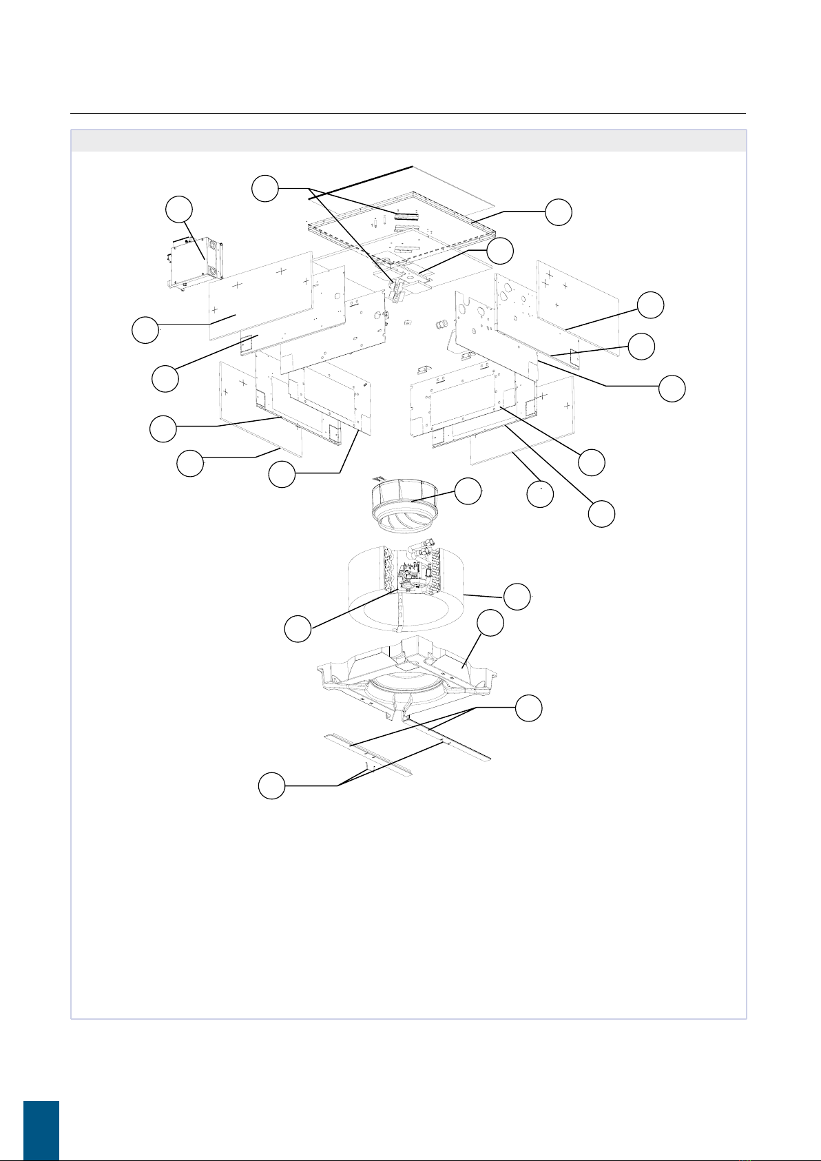
The suspended ceiling unit houses all the components, heat ex-
change coil, fan drive assembly, and condensate collection and
drainage system. Its structure is designed for introducing fresh
air into the space, mixing it with recovered air, and distributing
the treated air from the cassette unit to adjacent rooms.
The design and colour, RAL9003 or RAL9010, of the air intake
and diusion louvre guarantee optimal integration into the sus-
pended ceiling panels. Easy access to the air lter for cleaning
operations.
The unit can be supplied complete with valves, including pres-
sure-independent balancing and control valves, the use of
which signicantly reduces commissioning time.
OPERATING LIMITS
Thermal carrier uid: water
Water temperature: 5°C ÷ 70°C
Air temperature: 5°C ÷ 43°C
Supply voltage: 230 V - 50 Hz
Maximum water pressure during operation: 10 bar
Relative humidity limit of the ambient air:RH < 75% not
condensing
AVAILABLE VERSIONS
AQB0 Unit with one coil for 2-pipe systems
AQBB Unit with one coil for 4-pipe systems
Accessories supplied with the unit
Auxiliary water drip tray;
Installation and use manual;
Brackets for securing the unit.

WC66000403
All copying, even partial, of this manual is strictly forbidden 5
CONFIGURATOR
A Q 1 0 Q I B 0 0 0 00 00
1 2 3 4 5 6 7 9 1110 12 138
10
20
30
40
50
60
Q hydronic
cassette
0 3 speed
I Brushless
B standard 0 absent
B coil 1R
0 absent
A 3 way -
on/o 230V
2 2 way -
on/o 230V
B 3way -
modulating
4 2 way -
modulating
C 3 way -
on/o 24V
6 2 way -
on/o 24V
7 3V on/o
230V C.A.
8 2V on/o
230V C.A.
H 2V press.
Ind. ON/OFF
I 2V press.
Ind. Modul.
0 absent
E EVO board
G opz.E +
NAVEL wi
0 absent
1
SA
2
SW
3
SU
4 SA+SW
5 SA+SU
6 SA+SU+SW
0 absent
6 shell valves
0
none
0A rst release
A
Family Size Version Motor Std.Coil DF Coil Valves Control Probe Accessories
various
Various
options Release / Special
GRILLE CONFIGURATOR
A Q Y G R 3 0 F1A
12345678
Family SizeVersion Control Variants Release
GR grid 30 AQ10-20-30
60 AQ40-50-60
F wire 1 RAL9003
2 RAL9010
A rst release
AVAILABLE ACCESSORIES
Electronic microprocessor control panels with display
DIST MY COMFORT controller spacer for wall mounting
EVO-2-TOUCH 2.8”touch screen user interface for EVO control
EVOBOARD Circuit board for EVO control
EVODISP User interface with display for EVO controller
EYNAVEL Device forWi-Fi or Bluetooth communication between EVOBOARD and smartphone
MCLE Microprocessor control with display MY COMFORT LARGE
MCSUE Humidity sensor for MY COMFORT (medium e large), EVO
MCSWE Water sensor for MYCOMFORT and EVO controllers
Electronic microprocessor control panels
TED 10 Electronic controller for BLDC fan equipped with inverter and ON/OFF valves 230V
TED SWA Water temperature sensor forTED controls

ACQVARIA I
TECHNICAL MANUAL6
Valves
PIC-AQi PRESSURE-INDEPENDENT 2-way valves for models with 1 or 2 coils
V2-AQi 2-way valve, ON/OFF or MODULATING actuator, 230V or 24 V power supply, hydraulic kit, for model with 1 or 2 heat exchangers
V3-AQi 3-way valve, ON/OFF or MODULATING actuator, 230V or 24 V power supply, hydraulic kit, for model with 1 or 2 heat exchangers
Plenum, air intake modules, air inlet and outlet connectors
BAR Spigot for introduction of mixed renewal air
PAR Plenum for introduction of unmixed renewal air
PMAA Air outlet plenum

WC66000403
All copying, even partial, of this manual is strictly forbidden 7
2 MAIN COMPONENTS
2.1 STRUCTURE
Made of galvanised steel sheet with internal polyurethane foam
coating and external closed-cell polyethylene foam to guaran-
tee heat and sound insulation. Fresh air can be introduced in-
to the room directly through the unit due to the provision of
connections for neutral or mixed introduction. Accessories are
available for connection to ducts. There are systems on the unit
for anchoring it to the ceiling. The electrical wiring is housed in
a containment box and is easily accessible from the side for easy
connection.
2.2 AIR FILTER
Honey-comb polypropylene washable air lter, easily removable for maintenance operations.
2.3 HEAT EXCHANGER
Copper pipe and high eciency aluminium ns secured to the
pipe by mechanical expansion. With at least two rows in the
models for 2-pipe systems, it is available in the 2+1 conguration
in the models for 4-pipe systems. The coil comes complete with
manual air vent valves. On request, valves can be connected to
the coil to regulate and balance the operation of the unit.
2.4 FAN DRIVE ASSEMBLY
Inverter-controlled permanent magnet BLDC electric motor
(integrated in the GreenTech models) directly connected to a
centrifugal fan with backward-curving blades with prole opti-
mised for stable operation at all speeds.
2.5 CONDENSATE COLLECTION SYSTEM
Located under the heat exchanger, the main drip tray is made of
polystyrene and is inserted inside the proles optimised for the
distribution of air in the room. The supply is completed by the
auxiliary water drip tray for the collection of condensate from
the regulating valves.
2.6 CONDENSATE DISCHARGE SYSTEM
The condensate drainage pump, with built-in check valve, can
lift the condensate up to 0.9 m from the exit point from the unit.
The operation of the pump is controlled by a oat switch with
three levels of action that activate it and stop it during normal
operation. If the critical water level inside the main drip tray is
exceeded, an alarm signal closes the control valves, stopping the
ow of water inside the exchanger.
2.7 LOUVRE
It is square shaped for the intake and diusion of air in the space,
and it is made of ABS, colour RAL9003 or RAL9010. The air intake
louvre can be opened for access to the air lter. Air is diused in
the space through the 4 sides, each of which is equipped with an
adjustable n with suitable thermal insulation.

ACQVARIA I
TECHNICAL MANUAL8
2.8 EXPLODED VIEW
» 2.2 Exploded view, units AQ 10-20-30
1. Locking clips
2. Tie rods
3. Condensate drip tray
4. Condensate drainage pump
5. Heat exchanger
6. Fan drive assembly
7. External insulation
8. Internal insulation
9. Lateral sheet metal
10. Sheet metal back
11. Fan drive assembly support bracket
12. Exchanger support brackets
13. Electric box
2
4
5
6
11
10
12
13
3
1
7
7
9
9
8
7
7
9
9
8
8

WC66000403
All copying, even partial, of this manual is strictly forbidden 9
» 2.3 Exploded view, units AQ 40-50-60
1. Locking clips
2. Tie rods
3. Condensate drip tray
4. Condensate drainage pump
5. Heat exchanger
6. Fan drive assembly
7. External insulation
8. Internal insulation
9. Lateral sheet metal
10. Sheet metal back
11. Reinforcement brackets
12. Exchanger support brackets
13. Electric box
1
2
3
5
7
7
7
7
9
9
9
9
9
12
11
10
88
8
8
13
4

ACQVARIA I
TECHNICAL MANUAL10
3 AIR RANGE
• Flap inclination 45°
Model AQ10 AQ20 AQ30 AQ40 AQ50 AQ60
Control
voltage V 2,00 3,50 4,50 6,00 2,00 4,0 5,5 8,0 2,00 4,0 6,5 10,0 2,00 3,0 5,0 10,0 2,00 3,0 5,0 8,0 2,00 4,0 6,5 10,0
Air range X (m) 2,3 3,4 3,8 4,3 2,3 3,5 4,2 4,7 2,3 3,5 4,4 5,2 3,7 4,4 4,9 5,5 3,7 4,1 4,7 5,1 3,7 4,4 5,0 5,5
Height Y (m) 1,5 2,2 2,5 2,8 1,5 2,4 2,8 3,1 1,5 2,4 3,0 3,4 2,3 2,7 3,0 3,4 2,3 2,5 2,9 3,3 2,3 2,7 3,1 3,4
Distance Z (m) 1,9 2,5 2,8 3,2 1,9 2,6 3,1 3,6 1,9 2,6 3,3 3,9 2,9 3,4 3,8 4,4 2,9 3,2 3,7 4,0 2,9 3,4 3,9 4,4

WC66000403
All copying, even partial, of this manual is strictly forbidden 11
4 INSTALLATION
WARNING: unit installation and start-up must be entrusted
to competent personnel and performed in a workmanlike
manner, in accordance with current regulations.
WARNING: It is mandatory to install the 3-way (or 2-way)
valve accessory in order to avoid the circulation of cold
water in the exchanger if the unit is not operated for
long periods of time, with the fan o. Install the auxiliary
water drip tray, provided together with the base unit, in
order to prevent valve kits from dripping.
For each unit an (IL) switch should be mounted on the power
supply, with opening contacts at a distance of at least 3 mm
and a suitable protection fuse (F) .
WARNING: before carrying out any operation, check that
the voltage and frequency of the unit correspond exactly
to those of the main power supply.
WARNING: Install the unit, circuit breaker (IL) and/or any re-
mote controls in a place out of reach of persons who may be
taking a bath or shower.
WARNING: the EMC lters connected to frequency con-
verters (inverters) can create leakage currents toward
ground (in order to make the unit EMC compliant, by re-
ducing conducted emissions on power supply line). De-
pending on installation site, this can force the cut out of the
dierential safety switch. It is recommended to install a sepa-
rate dierential safety switch, only for the BLDC unit, with an
adjustable threshold for the cut out current.
WARNING: keep the unit's grille in its original packaging
until nal assembly.
RECOMMENDED: to ensure optimal comfort (homoge-
neous air temperature in the room), it is recommended not
to exceed a heat exchanger water inlet temperature of 55 °C.
WARNING: during a shutdown for installation, in the event
of a connection to a fresh air intake or an ambient tempera-
ture close to 0 °C, there is a risk of the pipes freezing. Provide
drainage for the water circuit.
4.1 INSTALLATION REQUIREMENTS
The fan coils should be installed in a position where the room
can be heated or cooled evenly, on ceilings able to support their
weight. Store the unit in its packaging until you are ready to in-
stall it.
For installation and use of accessories, please refer to the relative
technical sheets.
Install any remote control panel in an easily accessible position
allowing the user to set the functions while ensuring an accurate
reading of the ambient temperature, if provided.
Avoid therefore:
positions directly exposed to sunlight;
positions exposed to direct currents of warm or cold air
placing obstacles that impede an accurate temperature
reading
NB: The water sensor, where present, must be mounted in
the appropriate trap on the valve kit, on the INLET pipe.
1 Water sensor holder
1
If a valve kit other than the one suggested is used, it is neces-
sary to install the sensor on the INLET pipe, by means of the
special copper socket lled with conductive paste.
Lastly, the sensor must be properly isolated to ensure that it
reads the water temperature correctly.
NB: The air and humidity sensors, where present, must be at-
tached in the appropriate section located in the intake area
of the base unit.
1 Sensor retainer
1
Make the plumbing connections to the heat exchanger and,
where the cooling function is to be used, to the condensate
drainage outlet.
WARNING:
In normal operation, particularly with the fan at minimum
speed and ambient air with high relative humidity, conden-
sation may form on the air outlet and on some external parts
of the unit.
To avoid such issues while always remaining within the oper-
ating limits envisaged for the unit, it is necessary to limit the
inlet temperature of the water inside the heat exchanger. In
particular, the dierence between the air dew point (TA,DP)
and the inlet water temperature (TW) must NOT exceed 14
°C, according to the following relationship: TW>TA,DP-14
°C
Example: in the case of ambient air at 25 ° C with 75% rela-
tive humidity, the dew point temperature is about 20 ° C and
therefore the inlet temperature of the water in the battery
must be greater then:
20-14 = 6 °C in order to avoid condensation on a fancoil
equipped with a valve.

ACQVARIA I
TECHNICAL MANUAL12
Fan coil with valve
Air temperature dry bulb (°C)
21 23 25 27 29 31 33
Relative
humidity %
40 5555555
50 5555568
60 55557911
70 5 5 6 8 9 11 13
80 5 6 8 10 12 14 16
90 6 8 10 12 14 16 18
If the valves are not installed, there could be abundant con-
densation, especially if the unit is not operated for long pe-
riods of time.
During wintertime periods of quiescence, drain water from the
system, to prevent ice from forming. If anti-freeze solutions are
used, check for their freezing point using the table below.
% Glycol by weight Freezing
temperature (°C)
Capacity
adjustment
Pressure drop
adjustment
0 0 1,00 1,00
10 -4 0,97 1,05
20 -10 0,92 1,10
30 -16 0,87 1,15
40 -24 0,82 1,20
4.1.1 Electrical connections
Make the electrical connections whilst the power supply is
disconnected, in accordance with current safety regulations,
carefully following the wiring diagram and its legend.
Check that the mains electricity supply is compatible with the
voltage shown on the unit rating plate.
The electrical connections indicated must be made by the
installer.
For each fan coil a switch (IL) should be mounted on the power
supply, with opening contacts at a distance of at least 3 mm and
a suitable protection fuse (F).
For the electrical connections of the controls, follow the dia-
grams in the gures from:p.20.
WARNING: The power supply to the pump-oat switch de-
vice must never be interrupted.
4.1.2 Galletti control dedicated (EVO - TED - MY
COMFORT)
Galletti controls implement a logic that makes it possible to set
a xed speed (shown in the gure with analog signal 3, 6, 8 V)
or automatic speed modulation, that takes full advantage of the
BLDC motor.
The automatic logic varies the analog signal to the motor be-
tween 2 and 10 V, based on the distance from the set-point, in
order to accelerate the implementation phases and then settle
at a very low holding speed.
SET
2V
SET
SET + DEADZONE
AUTO
AUTO
SET - DEADZONE
SET + DEADZONE + 3°C
SET - DEADZONE - 3°C
2V
6V
3V
°C
°C
8V
6V
3V
8V
4.1.3 Hydraulic connections
Unit Exchanger connection
AQ10B0, AQ20B0, AQ30B0
(2 pipes) 1/2’’gas F
AQ40B0, AQ50B0, AQ60B0
(2 pipes) 3/4’’gas F
Cooling Heating
AQ10BB, AQ30BB (4 pipes) 1/2’’gas F 1/2’’gas F
AQ40BB, AQ60BB (4 pipes) 3/4’’gas F 1/2’’gas F
To optimise performance, it is advisable to make the following
connections on the exchanger:
Unit outlet: connection below.
Unit return: connection above.
WARNING: While making the connections, hold the water
connections of the unit tightly in place with a hexagonal
wrench or make sure that they do not rotate, in order to pre-
vent the pipes inside the unit from being damaged.
Carefully insulate the inlet and outlet water pipes as well as
the devices installed in the network (on/o valves…). Use a
material that is suitable for the operating conditions and wa-
ter temperature.
Bleed air from the exchanger by means of the air vent valves
located next to the water connections of the coil. Depending
on the installation, it may be necessary to place other vent
valves on the hydraulic system.
4.1.3.1 Condensate drain connection
Connect a rigid PVC pipe to the end of the hose and secure it
with a clamp

WC66000403
All copying, even partial, of this manual is strictly forbidden 13
Correctly insulate the pipe with polyethylene foam.
Be careful of the risk of freezing in winter in suspended ceil-
ings.
If necessary, the condensate pipe can be routed immediately
after the unit's outlet. Maximum height: 900 mm (FIGURE 1).
Make sure that the drainpipe has a slight slope in the direc-
tion of ow and that it does not form a siphon (FIGURE 1).
The piping must have several supports (FIGURE 2).
Do not install an air vent (FIGURE 3) in the wrong position.
» Fig.1
» Fig.2
» Fig.3
4.2 DIMENSIONAL UNIT ASSEMBLY
Use the dimensional drawings to determine the position of
the suspension rods (Fig.4 AQ 10-20-30) (Fig.5 AQ 40-50-60)
Position the suspension rods (not supplied) in place.
Attach the supplied brackets (Fig.6 ) to the suspension rods
(Fig.7 ). The length of the suspension rods depends on the
space between the suspended ceiling and the structural
ceiling.
The distance C (Fig.7 ) must be:
Model C- Bracket distance to the false
ceiling
ACQVARIA 10-20-30 270
ACQVARIA 40-50-60 312
Pay attention to the excess length B of the suspension rod
(Fig.7 ): it may interfere with the unit's electrical box.
Place the fan coil unit in the suspended ceiling, orienting
the side with the water connections in the most appropriate
position, using the hooks on the brackets to provide quick
temporary installation.
Then attach the unit to the threaded bars with the screws
provided and check that it is level (Fig.8 )
Adjust the distance between the unit and suspended ceiling
D (Fig.9 AQ 10-20-30 andFig.10 AQ 40-50-60) using the nuts
of the suspension rods:
Model D - Distance from unit to false
ceiling
ACQVARIA 10-20-30 23
ACQVARIA 40-50-60 48
Make sure that the unit does not touch the ceiling: contact
may cause noise.
» Fig.4 AQ 10-20-30

ACQVARIA I
TECHNICAL MANUAL14
» Fig.5 AQ 40-50-60
» Fig.6
» Fig.7
1. Nut + washer
2. Washer + nut + lock nut
» Fig.8
» Fig.9 AQ10-20-30
» Fig.10 AQ40-50-60

WC66000403
All copying, even partial, of this manual is strictly forbidden 15
4.2.1 Front panel/grille assembly
The front panel/grille, available in RAL9003 and RAL9010 ver-
sions, is delivered in a separate cardboard box:
AQYGR30 for models AQ 10-20-30
AQYGR60 for models AQ 40-50-60
Before installing the front panel: (Fig.11 )
Remove the screws (1) securing the retainers (2) on each side
(remember to put these screws back in place after installa-
tion).
To open the grille (3), move the two retainers (2) in the direc-
tion of the arrow.
Open the grille (3) by 45°.
Detach the control panel’s safety cable (4) (remember to at-
tach it again after installation).
Lift the grille to remove it from the control panel.
» Fig.11
To install the front panel: (Fig.12 )
Turn the two locking clips (5) downwards.
Attach the control panel of the panel (6) to the unit by means
of the two hooks (7), matching them to the locking clips (5).
Check the exact position of the panel's control panel in re-
lation to the suspended ceiling. Adjust the position of the
indoor unit as necessary.
Attach the panel's control panel to the unit using the special
screws and washers (8) provided.
Put the grille (3) in place, making sure that the lter (9) is cor-
rectly positioned.
Hook the safety cable to the control panel, close the grille,
and put the screws securing the retainers (2) back in place.
» Fig.12

ACQVARIA I
TECHNICAL MANUAL16
5 RATED TECHNICAL DATA
» Rated technical data ACQVARIA - 2 pipes
ACQVARIA AQ10B0 AQ20B0 AQ30B0
Speed 123412341234
Control voltage V 2,00 3,50 4,50 6,00 2,00 4,00 5,50 8,00 2,00 4,00 6,50 10,0
Total cooling capacity (1) kW 1,33 1,93 2,24 2,63 1,49 2,68 3,40 4,39 1,54 2,76 3,95 5,23
Sensible cooling capacity (1) kW 0,99 1,51 1,81 2,20 1,03 1,94 2,54 3,41 1,05 1,98 2,96 4,11
FCEER class A
Water flow (1) l/h 229 331 385 452 256 460 584 754 264 473 678 898
Water pressure drop (1) kPa 2 4 5 7 3 10 15 23 3 9 18 29
Heating capacity (2) kW 1,49 2,27 2,70 3,25 1,42 2,69 3,48 4,58 1,47 2,77 4,09 5,55
FCCOP class A B B
Water flow (2) l/h 258 395 470 565 248 468 605 797 255 481 711 965
Water pressure drop (2) kPa 2 5 6 9 3 8 13 21 3 8 16 27
Rated air flow m³/h 212 397 454 583 187 397 551 796 190 397 650 980
Power input W 6 6 9 17 6 9 14 37 6 10 21 67
Total sound power level (3) dB(A) 28 35 40 46 28 37 44 54 29 38 49 61
Cross-section area of power cables (4) mm² 1,00 1,00 1,00
Power supply cable type N07V-K
Safety fuse F A 2 2 2
Fuses type gG
ACQVARIA AQ40B0 AQ50B0 AQ60B0
Speed 123412341234
Control voltage V 2,00 3,00 5,00 10,0 2,00 3,00 5,00 8,00 2,00 4,00 6,50 10,0
Total cooling capacity (1) kW 4,80 5,36 6,39 8,27 5,17 5,92 7,26 9,01 5,26 6,70 8,17 10,5
Sensible cooling capacity (1) kW 3,80 3,92 4,75 6,35 3,66 4,24 5,31 6,78 3,69 4,80 6,06 7,97
FCEER class A A B
Water flow (1) l/h 833 921 1097 1420 888 1015 1245 1545 902 1150 1401 1805
Water pressure drop (1) kPa 12 16 21 34 10 13 18 27 10 15 23 33
Heating capacity (2) kW 5,50 6,00 7,30 9,74 5,43 6,33 7,99 10,2 5,48 7,23 9,14 12,2
FCCOP class A B B
Water flow (2) l/h 953 1043 1269 1692 944 1100 1390 1779 952 1257 1590 2116
Water pressure drop (2) kPa 3 16 23 38 9 12 19 29 9 15 24 36
Rated air flow m³/h 843 978 1276 1916 724 864 1143 1554 710 976 1350 1831
Power input W 13 18 36 150 15 18 36 93 15 25 60 150
Total sound power level (3) dB(A) 35 39 45 57 35 39 45 53 36 43 50 58
Cross-section area of power cables (4) mm² 1,00 1,00 1,00
Power supply cable type N07V-K
Safety fuse F A 2 2 2
Fuses type gG
(1) Water temperature 7°C / 12°C, air temperature dry bulb 27°C, wet bulb 19°C (47% relative humidity) according to EN1397:2015
(2) Water temperature 45°C / 40°C, air temperature 20°C
(3) Sound power measured according to standards ISO 3741 and ISO 3742
(4) The shown section is to be considered as the minimum recommended section.The cables must be chosen in compliance with CEI - UNEL 35024/1. standard.
Power supply 230-1-50 (V-ph-Hz)

WC66000403
All copying, even partial, of this manual is strictly forbidden 17
» Rated technical data ACQVARIA - 4 pipes
ACQVARIA AQ10BB AQ30BB AQ40BB AQ60BB
Speed 1234123412341234
Control voltage V 2,00 3,50 4,50 6,00 2,00 4,00 6,50 10,0 2,00 3,00 5,00 10,0 2,00 4,00 6,50 10,0
Total cooling capacity DF 1R (1) kW 1,24 1,85 2,18 2,60 1,26 2,05 2,80 3,61 4,61 5,34 6,61 9,07 4,70 6,09 7,62 9,50
Sensible cooling capacity DF1R (1) kW 0,92 1,46 1,79 2,23 0,92 1,62 2,38 3,31 3,34 3,94 5,03 7,29 3,37 4,50 5,82 7,56
FCEER class DF A A A B
Water flow DF 1R l/h 213 317 374 447 216 352 480 620 792 917 1135 1555 806 1045 1307 1631
Water pressure drop DF 1R kPa 2 4 6 8 2 5 9 14 12 15 22 37 11 17 25 37
Heating capacity DF 1R (2) kW 2,03 2,90 3,34 3,86 2,04 3,14 4,06 4,98 7,01 7,96 9,53 12,3 7,15 8,96 10,8 12,9
FCCOP class DF 1R A B A B
Water flow DF 1R (2) l/h 178 254 292 338 178 275 356 435 613 697 834 1078 626 785 947 1133
Water pressure drop DF 1R (2) kPa 3 6 8 11 3 7 11 16 11 14 19 30 12 18 24 33
Rated air flow DF 1R m³/h 199 356 460 610 195 395 643 982 687 841 1137 1823 673 956 1314 1823
Power input DF 1R W 6 6 9 17 6 11 21 67 15 18 36 150 15 25 60 150
Total sound power level DF 1R (3) dB(A) 28 35 40 46 29 38 49 61 35 39 45 57 36 43 50 58
Cross-section area of power cables (4) mm² 1,00 1,00 1,00 1,00
Power supply cable type N07V-K
Safety fuse F A 2 2 2 2
Fuses type gG
(1) Water temperature 7°C / 12°C, air temperature dry bulb 27°C, wet bulb 19°C (47% relative humidity) according to EN1397:2015
(2) Water temperature 65°C / 55°C, air temperature 20°C
(3) Sound power measured according to standards ISO 3741 and ISO 3742
(4) The shown section is to be considered as the minimum recommended section.The cables must be chosen in compliance with CEI - UNEL 35024/1. standard.
Power supply 230-1-50 (V-ph-Hz)
ACQVARIA AQ 10-20-30 AQ 40-50-60
CONDENSATE DRAINAGE PUMP
Power supply V - ph - Hz 230 - 1 -50 230 - 1 -50
Rated current l/h 24 24
Lifting height above the unit mm 900 900
Power input kW 0,011 0,011
INTAKE OF FRESH AIR TO BE TREATED
Number of intakes nr 3
Connection dimensions mm Ø 100
OUTLET OF AIR IN ADJACENT ROOMS
Number of intakes nr 2 2
Connection dimensions mm Ø 150 Ø 180
INTRODUCTION OF FRESH AIR DIRECTLY INTO THE ROOM
Number of intakes nr 2 2
Connection dimensions mm Ø 150 Ø 180
6 WEIGHTS
ACQVARIA AQ10 AQ20 AQ30 AQ40 AQ50 AQ60
Weight kg 23 + 2,5 23 + 2,5 23 + 2,5 43 + 5 43 + 5 43 + 5

ACQVARIA I
TECHNICAL MANUAL18
7 PERFORMANCES
Galletti has developed on its www.galletti.com web-area the new ON-LINE integrated platform for product selection, conguration
and the making of the economic oer.
The software, whose use is easy and intuitive, allows the identication of the desired products by calculating their performances
based on real working conditions and their conguration helping the user in choosing options and accessories. It also allows to ob-
tain a detailed report which includes performances, dimensional drawings, tender specications and the economic oer.
Product selection:
Filters to make the identication of the requested product easier
Performance calculation and saving of results
Performance comparison between products belonging to dierent series
Conguration and project history
Wizard conguration of accessories and options for chillers, heat pumps and
hydronic units
Creation of a project which collects all products of interest
Complete management of the storaged history projects
Report:
Generation of a detailed list report in pdf format
Choice of the sections to be included in the print:
Products performances
Dimensional drawings
Tender specications

WC66000403
All copying, even partial, of this manual is strictly forbidden 19
8 SOUND LEVELS
Lw: Sound power level by octave band, not weighted LwA: Total sound power level, weighted A
ACQVARIA i
Lw LwA
Contol voltage 125 Hz 250 Hz 500 Hz 1000 Hz 2000 Hz 4000 Hz 8000 Hz
V dB dB dB dB dB dB dB dBA
AQ 10
2 31,1 31,8 26,6 21,4 11,1 9,3 12,1 28,0
3,5 36,7 37,7 33,8 29,7 23,4 11,9 7,7 35,0
4,5 41,8 42,8 38,9 34,8 28,5 17,0 12,8 40,0
6 47,5 48,5 44,6 40,5 34,2 22,6 18,5 46,0
AQ 20
2 31,3 32,0 26,8 21,6 11,3 9,5 12,3 28,0
4 38,8 39,8 35,9 31,8 25,5 14,0 9,8 37,0
5,5 45,9 46,9 43,0 38,9 32,6 21,1 16,9 44,0
8 53,3 55,4 52,1 48,2 44,4 38,5 27,7 54,0
AQ 30
2 32,3 33,0 27,8 22,6 12,3 10,5 13,3 29,0
4 39,7 40,7 36,8 32,7 26,4 14,9 10,7 38,0
6,5 50,8 51,8 47,9 43,8 37,5 26,0 21,8 49,0
10 60,3 62,3 59,0 55,2 51,4 45,5 34,7 61,0
AQ 40
2 37,7 38,3 34,3 26,8 19,5 18,2 20,4 35,0
3 40,3 42,2 36,8 33,7 25,8 17,4 17,1 39,0
5 45,4 47,3 43,2 39,3 34,8 26,4 19,4 45,0
10 56,7 59,3 55,3 51,0 48,1 43,5 35,3 57,0
AQ 50
2 38,0 38,6 34,6 27,1 19,8 18,5 20,7 35,0
3 40,6 42,5 37,1 34,0 26,1 17,7 17,4 39,0
5 45,7 47,6 43,5 39,6 35,1 26,7 19,7 45,0
8 55,0 55,5 51,3 46,8 44,1 37,6 28,7 53,0
AQ 60
2 38,4 39,0 35,0 27,5 20,2 18,9 21,2 36,0
4 44,7 46,6 41,2 38,1 30,3 21,8 21,5 43,0
6,5 50,3 52,2 48,1 44,2 39,7 31,3 24,3 50,0
10 57,4 59,9 55,9 51,6 48,7 44,1 36,0 58,0

ACQVARIA I
TECHNICAL MANUAL20
9 ELECTRICAL CONNECTION DIAGRAMS
WARNING: The traced electrical connections must be made by the installer.
For each unit an (IL) switch should be mounted on the power supply, with opening contacts at a distance of at least 3 mm and a
suitable protection fuse (F) .
Make the electrical connections with the power supply disconnected, in accordance with current safety regulations, and following
the base wiring diagram and pertinent legend.
Check that the mains electricity supply is compatible with the voltage shown on the unit rating plate.
» 9.1 My Comfort Large wiring diagram for models AQ 10-20-30
MV : Fan motor
MP: Condensate drainage pump
FLOAT: Float switch
VC/H: Water valve (hot and cold)
F: 2A fuse (not supplied)
IL: Circuit breaker (not supplied)
CN: Fast-on connector
EMC FILTER: EMI/RFI noise lter
SU: Umidity sensor
SW: Water temperature sensor
SA: Room temperature sensor
BK (MV): Black = motor power supply line
BU (MV): Blue = motor power supply neutral
blue (MV): Blue = GND control signal
yellow (MV): Yellow = 0-10V signal
BN (FLOAT): Brown = pump power supply line
BU (FLOAT): Blue = pump power supply neutral
BK (FLOAT): Black = oat switch alarm signal
GY (FLOAT): Grey = COM alarm
BN (VC/H): Brown = valve actuator line
BU (VC/H): Blue = valve actuator neutral
BN (L2 FILT): Brown = lter IN line
BU (N4 FILT): Blue = lter IN neutral
BK (U1 FILT): Black = lter OUT line
BU (U3 FILT): Blue = lter OUT neutral
This manual suits for next models
1
Table of contents
Other Galletti Chiller manuals
Popular Chiller manuals by other brands

McQuay
McQuay ACZC SE-ST Installation, operation and maintenance manual

AERMEC
AERMEC NRL F Series installation manual

York
York YCAL0019 Installation operation & maintenance

Water Furnace
Water Furnace ENVISION 2 NKW Series manual

Aquacal
Aquacal TropiCal T035 Operation manual

Hitachi
Hitachi SAMURAI Series Service manual

Carrier
Carrier 30HK Installation, Start-Up and Service Instructions

Advantage
Advantage MGD-15W-MGD-ADV-02 instruction manual

Midea
Midea LSBLG365/MCFN Technical & service manual

Kaysun
Kaysun KHP-MO 4 DVP Installation and owner's manual

Samsung
Samsung DVM installation manual

Daikin
Daikin AGZ030E Installation, operation and maintenance manual