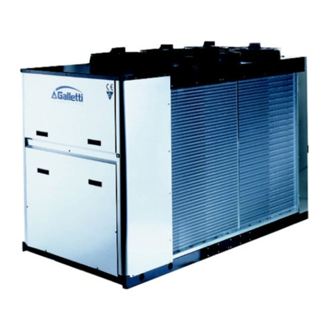
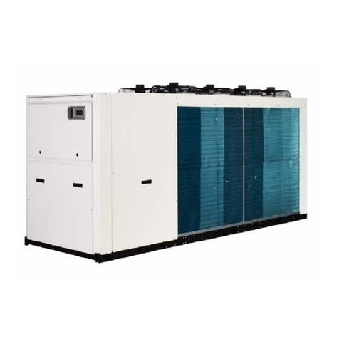
Galletti MCA Series User manual

GB
water chillers and heat pumps technical manual
EUROVENT
CERTIFIED PERFORMANCE

2
RG66002124 - Rev 05
MCA
All copying, even partial, of this manual is strictly forbidden
INDEX
1 THE RANGE ............................................................................. 2
2 CONSTRUCTIVE FEATURES ..................................................... 2
3 COMPONENTS LAY-OUT .......................................................... 3
4 MODELS AND CONFIGURATIONS ............................................. 5
5 TECHNICAL FEATURES ............................................................. 6
5.1 Rated tecnical data cooling mode ............................................ 6
5.2 Rated tecnical data heating mode ........................................... 7
6 PERFORMANCES ..................................................................... 8
6.1 Cooling capacities MCA-C ...................................................... 8/9
6.2 Cooling capacities MCA-H .................................................... 10/11
6.3 Heating capacities MCA-H .................................................... 12/13
7 OPERATING LIMITS ................................................................. 14
7.1 Cooling mode ......................................................................... 14
7.2 Heating mode ......................................................................... 14
8 HEAT RECOVERY .................................................................... 14
9 CALCOLATION FACTORS ......................................................... 14
9.1 Water temperature drop/rise different than 5°C ........................ 14
9.2 Glicol and water solution ........................................................ 14
10 PRESSURE DROP ON WATER SIDE ........................................ 15
11 AVAILABLE STATIC PRESSURE ............................................... 16
12 HYDRAULIC CIRCUIT .............................................................. 17
13 ELECTRICAL DATA AND CONNECTIONS .................................. 18
14 OVERALL DIMENSIONS ........................................................ 19/22
15 MINIMUM TECNICAL SPACES ................................................. 23
1 THE RANGE
MCA water chillers and heat pumps are designed for outdoor installation in
residential applications. The large number of models (sizes) making up the
series and the available accessories allow a broad range of possible
configurations, which make the MCA series an ideal solution for speeding up
installation on the building site. Only top quality components are used for the
cooling,aircirculationandelectric systems, guaranteeingefficiency, reliability
and reduced noise levels.
2 CONSTRUCTIVE FEATURES
REFRIGERANT: R407C
STRUCTURE
The MCA units are built with a galvanised sheet steel supporting base and
enclosing panels made of Peraluman which provides effective protection
against corrosive agents. All bolts and screws and fastening devices are
made of non-oxidizable materials, stainless steel or carbon steel that has
been subject to surface-passivating treatments. The compressor
compartment is completely sealed and may be accessed on 3 sides thanks
toeasy-to-remove panels thatgreatly simplify maintenanceand/or inspection.
MICROPROCESSOR CONTROL
The µChiller control panel allows
the full management of the MCA
units and is easly reachable throw
a polycarbonate door, with IP 65
protection degree.
Main functions:
- control of the water inlet temperature in the evaporator
- management of the defrosting (MCA-H)
- control of the fan speed (optional on the cooling only MCA-C)
- full management of the alarms
- possibility to be connected to the RS485 serial board for supervision
and teleassistance
- connection with an external terminal (PCD optional)
Controlled devices:
- compressors
- fans
- cycle reversing valve (only for heating pump MCA-H)
- circulating pump
- antifreeze resistence (optional)
- alarm relay
The end user can change the parameter settings shown in the table within
the limits indicated.
Parameter min standard max
Setting of cooling regulation sensor (°C) 9 11,5 15
Tripping of anti-freeze sensor (°C) 2 3 4
Lag in response of cooling regulation sensor (°C) 0,1 2 12
All other parameters may be adjusted by an AUTHORISED SERVICE CENTRE
by means of a programming access key, except for the machine
configuration, which may be modified exclusively by GALLETTI S.p.A.
The technical and dimensional data reported in this manual may be modified
in view of any product improvement.
DECLARATION OF CONFORMITY
Galletti S.p.A. hereby declares, under its sole responsibility, that the
water chillers and heat pumps belonging to the MCA series have
been designed, built and tested in conformity with the specifications
of European Directives:
· 98/37/CE (Machinery Directive)
· 73/23/CEE (Low Voltage Directive)
· 89/336/CEE (Directive on Electromagnetic Compatibility)
· 97/23 CE (PED)
Bentivoglio,01/06/2002
Galletti S.p.A.
Luigi Galletti

3RG66002124 - Rev 05
All copying, even partial, of this manual is strictly forbidden
MCA
2 CONSTRUCTIVE FEATURES
REFRIGERANT CIRCUIT
- scroll compressor fitted in a sound proofed compartment.
- inox braze - welded plate heat exchangers.
- finned block condenser coil with copper pipping and aluminium fins.
- dehydration filter.
- refrigerant sight glass with humidity indicator.
- thermostatic valve with external equalization and integrated MOP function.
- cycle - reversing valve (heat pump models only).
- check valves (heat pump only).
- liquid receiver (heat pump only).
- high and low pressure switches.
- safety valve.
- Schrader valves for checks and/or maintenance.
- refrigerant manometers (options).
TAYLORED HYDRONIC KIT
To simplify the connection of the MCA unit to user plant , 2 different hydraulic
kit are available.:
- base unit
- kit including water pump and expansion vessel
- kit including water pump and expansion vessel and buffer tank
The main features are:
- High performance pump with extended working range: suitable to operate
with glycol mix up to 30%.The pump is fitted in the compressors vane,
acoustically insulated and of easy access thanks to the openable
panels.The pump is provided with internal thermal protection.
- expansion vessel
- water safety valve
- automatic filling system
- automatic vent valve
- differential pressure switch and antifreeze thermostat with probe on
leaving water side.
- buffer tank dowstream to the evaporator, best solution to reduce the
chilled water variation due to the compressor ON/OFF operation.
VENTILATION SECTION
The units is including axial - type fans with airfoil - shaped blades, statically
and dynamically balanced on two levels provided with a protective outlet
grille with interposed rubber vibration dampers to riduce the propagation of
vibrations during speed modulating phases (optional).
The blades are made with thermoplastic material (model 10 out 21).
All the fans the motor are single-phase (3-phase for the 50 - 60 models) and
are protected with a thermal cutout. All are equipped with low - noise 6 pols
motors (900 rpm) with external rotor type to ensure maximum energy
efficiency and magnetic noise reduction.
ELECTRIC PANEL
The electric panel is built and wired according to the CEE 73/23 directive, to
the 89/336 directive for the electromagnetic compatibility and related
standards. Built with steel panels sheet, completely closed and protected by
the enclosing panels of the unit.
Housed inside the tecnical vane suitable for outdoor installation, is composed
by:
- compressors conctactors
- pump relay
- pump, fans, trasformer and main control box protection fuses
- 230V/24V tranformer
- terminal box
AVAILABLE OPTIONS
- refrigerant gauges
- antifreeze kit
- electronic expansion valve
- partial heat recovery system 20%(cooling only model)
- special treatment on coils (copper/copper, cataphoresys,Blygold)
- remote control board (PCD)
- simplified remote board (PDCS)
- condensing pressure control with fans speed variation(standard in
heat pump version MCA-H).
- antivibration mounting.
- protecting grid for condensing coils.
MCA 10 - 12 - 14 - 16 - 21
Description
1R407C-airheat-exchanger
2R407C-waterheat-exchanger
3Fans
4Water differential pressure switch (fan housing)
5Air purge valve
6Expansion vessel (fan housing)
7Water tank
8R407C safety valve
94-way valve (MCA H)
10 Thermostatic valve
11 Automatic filling device
12 Water safety valve
13 Liquid receiver (fan housing)
14 Pump
15 Compressor
16 Refrigerant filter (behind the compessor)
17 Low pressure switch and charge port
18 High pressure switch and charge port
1 5 72
3
6
4
9
8
18
15161714
11
12
10
13
3 COMPONENTS LAY-OUT

4
RG66002124 - Rev 05
MCA
All copying, even partial, of this manual is strictly forbidden
Description
1R407C-airheat-exchangers
2R407C-waterheat-exchanger
3Fan
4Water differential pressure switch (fan housing)
5Air purge valve (fan housing)
6Expansion vessel (fan housing)
7Water tank (fan housing)
8R407C safety valve
94-way valve (MCA H)
10 Thermostatic valve
11 Automatic filling device
12 Water safety valve
13 Liquid receiver
14 Pump
15 Compressor
16 Refrigerant filter
17 Low pressure switch and charge port
18 High pressure switch and charge port
3 COMPONENTS LAY-OUT
3 5 76
2
9
18
151617
14
4
10
12
11
13
1
8
1
2
3
14 15
567
4
12
5
11
10
13
16
18
8
9
MCA 25 - 30 - 37
MCA 50 - 60

5RG66002124 - Rev 05
All copying, even partial, of this manual is strictly forbidden
MCA
4 MODELS AND CONFIGURATIONS
The water chiller and heat pump of the MCA series are units that can be configured in order to meet the number of possible installation requirements.
To simplify the order, Galletti proposes 3 different solutions with integrated hydronic kit, both in the cooling only and heat pump versions:
WATER CHILLER
MCA..CB standard unit (only evaporator)
MCA..CP unit with pump and expansion vessel
MCA..CS unit with pump, expansion vessel and buffer tank
HEAT PUMP
MCA..HB standard unit (only evaporator)
MCA..HP unit with pump and expansion vessel
MCA..HS unit with pump, expansion vessel and buffer tank
The choice of some options can prevent the choice of others or render obligatory other fields. To contact the Galletti for verification
MC A 014C0A1S00S0M30G0
014
C
C
H
0
M
0
A
0
A
1
0
1
S
0
S
0
0
D
0
0
C
S
0
E
P
S
0
0
S
M
M
0
M
3
0
2
3
0
0
R
C
B
G
0
G
Standard
Cataphoresis
Blygold
Cond./evap. finned coil protection grille
Not present
Present
Not present
Remote control
Special heat exchanger features
Copper / copper heat exchanger
Connection to nets ergo
RS 485
Gauges
With microprocessor *
Accessories of the water circuit
Nobody
Remote control board
Heat recover
Simplified
Present, unit with pump, tank and vessel
Present, unit with pump and tank
Not present
Antifreeze kit
Not present
Present, standard unit
Electronic
Pump and epansion vessel
Water pump
Not present
Modulating air flow with fan speed control
Not present
Condensing control
Partial (desuperheater) 20%
Not present
Heat pump
Power supply
230V - 1 - 50 Hz
400V - 3 - 50 Hz
Present
Not present
Water storage tank
Expansion valve
Thermostatic
Name
Gives information on the cooling capacity of the standard model
Typology
Water chiller
0
0
1
2
3
Compressor options
Not present
Power factor correction capacitors
Soft starter
*To be requested at the moment of the order Power factor correction capacitors + Soft starte
r

6
RG66002124 - Rev 05
MCA
All copying, even partial, of this manual is strictly forbidden
5 TECHNICAL FEATURES
5.1 COOLING ONLY RATINGS
* Weights referred to version including pump and buffer tank
- Cooling capacity: outdoor air temperature 35°C, water temperature 12°C / 7°C
- Sound power level measured according to standards EN 23741 and EN 29614-1
- Sound pressure level measured at a distance of 10 m and a height of 1.5 m above the ground in a free field (fan side).
- The maximum electrical input is the mains electricity that must be available in order for the unit to work.
- The maximum current absorption refers to the current that will trigger the internal safety devices of the unit. It is the maximum current allowed in the unit.
This value may never be exceeded; it must be used as a reference for determining the size of the power supply line and the related safety devices (refer
to the wiring diagram supplied with the units).
MCA-C 10M10121416212530 37 50 60
Power supply V - ph - Hz 230-1-50
Cooling capacity kW 9,62 9,64 11,22 13,68 16,61 20,11 23,80 32,13 35,30 49,70 60,10
MCA CB Total power input kW 4,09 3,99 5,04 5,70 6,76 8,45 10,00 12,62 14,98 18,70 24,10
MCA CP CS Total power input kW 4,46 4,36 5,41 6,07 7,13 8,83 10,55 13,17 15,53 19,30 24,70
Maximum power input kW 5,6 5,5 6,5 7,5 9,0 10,7 12,9 16,8 19,0 26,0 34,0
Maximum current absorption A 28,4 12,4 14,4 16,1 18,4 21,4 28,0 33,0 37,2 44,0 58,0
Starting absorbed current A 117,4 54,4 69,9 78,4 102,4 134,4 138,0 143,0 183,0 190,0 240,0
n° of scroll compressors / circuits 1/1 1/1 1/1 1/1 1/1 1/1 1/1 1/1 1/1 1/1 1/1
Refrigerant charge kg 2,0 2,0 2,0 2,7 3,9 4,9 6,4 7,8 11,0 13,0 16,0
Low/high pressure switch bar 1,4 / 28 1,4 / 28 1,4 / 28 1,4 / 28 1,4 / 28 1,4 / 28 1,4 / 28 1,4 / 28 1,4 / 28 1,4 / 28 1,4 / 28
n° of axial fan 22222211111
Air flow m3/h 5580 5580 5580 5040 6300 5800 10750 10620 10500 19000 18000
Water flow l/s 0,460 0,460 0,536 0,654 0,794 0,961 1,137 1,535 1,688 2,375 2,871
Diameter of hydrualic connections " 1 1/4 1 1/4 1 1/4 1 1/4 1 1/4 1 1/4 1 1/4 1 1/4 1 1/4 2 2
Water side pressure drop kPa393934503337 42 39 36 26 26
Available pressure head kPa 151 151 154 134 144 132 130 126 125 78 121
Water content escluding optionals dm3111122233910
Expansion tank dm35555558881212
Buffer tank dm330 30 30 30 82 82 125 125 125 210 210
Height mm 1128 1128 1128 1128 1228 1228 1390 1390 1390 1589 1589
Length mm 1120 1120 1120 1120 1400 1400 1500 1500 1500 1989 1989
Depth mm 578 578 578 578 628 628 1050 1050 1050 1202 1202
Sound power level dB(A)696970717274 78 79 80 81 81
Sound pressure level dB(A)414142434446 50 51 52 53 53
Transport weight * kg 157 157 163 166 222 226 315 341 386 630 669
Operating weight * kg 172 172 178 181 297 301 430 456 501 816 855
400-3-50

7RG66002124 - Rev 05
All copying, even partial, of this manual is strictly forbidden
MCA
5 TECHNICAL FEATURES
5.2 HEAT PUMPS RATINGS
* Weights referred to version including pump and buffer tank
- Cooling capacity: outdoor air temperature 35°C, water temperature 12°C / 7°C
- Heating capacity: outdoor air temperature 7°C dry bulb and 6.2°C wet bulb, water temperature 40°C/45°C
- Sound power level measured according to standards EN 23741 and EN 29614-1
- Sound pressure level measured at a distance of 10 m and a height of 1.5 m above the ground in a free field (fan side).
- The maximum electrical input is the mains electricity that must be available in order for the unit to work.
- The maximum current absorption refers to the current that will trigger the internal safety devices of the unit. It is the maximum current allowed in the unit.
This value may never be exceeded; it must be used as a reference for determining the size of the power supply line and the related safety devices (refer
to the wiring diagram supplied with the units).
MCA-H 10M10121416212530 37 50 60
Power supply V - ph - Hz 230-1-50
Cooling capacity kW 9,25 9,28 10,77 13,18 16,49 19,30 22,86 30,95 33,90 48,20 58,30
MCA HB Cooling power input kW 4,20 4,09 5,15 5,84 6,93 8,67 10,26 12,94 15,34 18,70 24,10
MCA HP - HS Cooling power input kW 4,57 4,47 5,53 6,21 7,30 9,05 10,81 13,49 15,89 19,30 24,70
Heating capacity kW 11,19 11,13 12,90 16,01 19,62 23,10 26,79 37,52 41,81 57,10 71,40
MCA HB Heating power input kW 4,10 4,00 4,64 5,56 6,88 8,28 10,05 12,86 14,62 19,60 24,40
MCA HP - HS Heating power input kW 4,47 4,37 5,01 5,93 7,45 8,66 10,60 13,41 15,17 20,20 25,00
Maximum power input kW 5,6 5,5 6,5 7,5 9,0 10,7 12,9 16,8 19,0 26,0 36,0
Maximum current absorption A 28,4 12,4 14,4 16,1 18,4 21,4 28,0 33,0 37,2 44,0 58,0
Starting absorbed current A 117,4 54,4 69,9 78,4 102,4 134,4 138,0 143,0 183,0 190,0 240,0
n° of scroll compressor / circuits 1/1 1/1 1/1 1/1 1/1 1/1 1/1 1/1 1/1 1/1 1/1
Refrigerant charge kg 2,6 2,6 2,6 3,4 5,3 6,3 7,8 9,5 13,2 18,0 21,0
Low/high pressure switch bar 1,4 / 28 1,4 / 28 1,4 / 28 1,4 / 28 1,4 / 28 1,4 / 28 1,4 / 28 1,4 / 28 1,4 / 28 1,4 / 28 1,4 / 28
n° of axial fan 22222211111
Air flow m3/h 5580 5580 5580 5040 6300 5800 10750 10620 10501 19000 18000
Water flow in cooling mode l/s 0,442 0,443 0,514 0,630 0,788 0,922 1,092 1,479 1,620 2,304 2,785
Water flow in heat pump l/s 0,534 0,532 0,616 0,765 0,937 1,104 1,280 1,793 1,998 2,730 3,410
Diameter of hydrualic connections " 1 1/4 1 1/4 1 1/4 1 1/4 1 1/4 1 1/4 1 1/4 1 1/4 1 1/4 2 2
Water pressure drop (cooling) kPa3637324632353936 33 25 24
Water pressure drop (heating) kPa5252456745495252 49 33,7 36,0
Available pressure head (cooling) kPa 155 154 157 138 145 136 134 130 130 81 125
Available pressure head (heating) kPa 135 136 140 111 125 112 117 107 103 62 95
Water content escluding optionals dm311111,52233910
Expansion tank dm3555555888
12 12
Buffer tank dm330 30 30 30 82 82 125 125 125 210 210
Height mm 1128 1128 1128 1128 1228 1228 1390 1390 1390 1589 1589
Length mm 1120 1120 1120 1120 1400 1400 1500 1500 1500 1989 1989
Depth mm 578 578 578 578 628 628 1050 1050 1050 1202 1202
Sound power level dB(A)6969707172747879808181
Sound pressure level dB(A)4141424344465051 52 53 53
Transport weight * kg 162 162 172 176 235 246 334,5 364 410 665 694
Operating weight * kg 177 177 187 191 310,5 321,5 449,5 479 524,5 841 880
400-3-50

8
RG66002124 - Rev 05
MCA
All copying, even partial, of this manual is strictly forbidden
6 PERFORMANCES
6.1 COOLING CAPACITIES MCA-C
Tbs1Inlet air dry bulbe temperature
Tw in/out Inlet/outlet air temperature
PF Cooling capacity
PA Total electric absorbed power models with hydraulic kit (MCA-CP / MCA-CS)
TwinTwoutPFPAPFPAPFPAPFPAPFPA
[°C] [°C] kW kW kW kW kW kW kW kW kW kW
10 5 10,13,629,474,008,794,458,074,957,315,51
11 6 10,43,659,884,019,184,458,434,967,565,57
12 7 10,83,6810,24,049,624,468,705,017,805,63
13 8 11,13,7110,54,089,774,548,985,068,055,68
14 9 11,53,7510,74,1610,04,639,165,168,305,75
15 10 11,7 3,82 11,0 4,24 10,2 4,72 9,34 5,26 8,46 5,86
16 11 12,1 3,85 11,3 4,28 10,5 4,77 9,62 5,32 8,71 5,92
17 12 12,4 3,90 11,6 4,33 10,8 4,82 9,89 5,38 8,96 5,99
10 5 10,13,579,463,948,814,368,124,817,395,31
11 6 10,43,609,883,949,204,368,474,827,625,37
12 7 10,73,6310,23,989,644,368,744,877,865,42
13 8 11,13,6610,54,019,794,449,014,918,095,48
14 9 11,53,6910,74,0810,04,529,195,018,335,53
15 10 11,7 3,75 11,0 4,15 10,2 4,60 9,36 5,10 8,48 5,64
16 11 12,1 3,78 11,3 4,19 10,5 4,65 9,63 5,15 8,72 5,70
17 12 12,4 3,82 11,6 4,24 10,8 4,70 9,90 5,21 8,95 5,76
10 5 11,94,4311,14,8810,25,369,385,898,506,47
11 6 12,34,4911,64,9010,75,399,795,928,786,56
12 7 12,74,5511,94,9611,25,4110,16,009,066,65
13 8 13,14,6012,35,0311,45,5310,46,099,346,75
14 9 13,54,6712,65,1411,75,6610,76,239,626,85
15 10 13,8 4,77 12,9 5,25 11,9 5,79 10,9 6,38 9,80 7,02
16 11 14,3 4,84 13,3 5,33 12,3 5,87 11,2 6,47 10,1 7,13
17 12 14,7 4,91 13,7 5,41 12,6 5,96 11,5 6,58 10,3 7,24
10 5 14,44,9213,55,4512,56,0311,66,6710,67,36
11 6 14,84,9814,05,4613,16,0512,16,6911,07,46
12 7 15,35,0414,55,5313,76,0712,56,7811,47,55
13 8 15,85,1014,95,6013,96,2012,96,8611,77,65
14 9 16,35,1715,25,7214,26,3413,17,0212,17,76
15 10 16,6 5,28 15,5 5,85 14,4 6,48 13,4 7,18 12,3 7,93
16 11 17,0 5,35 15,9 5,93 14,9 6,57 13,8 7,28 12,7 8,05
17 12 17,5 5,43 16,4 6,01 15,3 6,66 14,2 7,38 13,1 8,16
10 5 17,55,8216,46,4315,17,1013,97,8512,58,67
11 6 18,15,8817,16,4415,87,1214,57,8712,98,76
12 7 18,75,9517,76,5116,67,1314,97,9613,38,86
13 8 19,46,0118,36,5816,97,2815,48,0513,78,97
14 9 20,06,0818,76,7217,37,4315,78,2214,19,07
15 10 20,5 6,20 19,1 6,86 17,6 7,59 16,1 8,39 14,4 9,27
16 11 21,1 6,27 19,7 6,94 18,2 7,68 16,5 8,49 14,8 9,38
17 12 21,8 6,35 20,3 7,03 18,7 7,78 17,0 8,60 15,2 9,50
45
MCA 10 MC
MCA 10 C
MCA 12 C
Tbs125 30 35 40
MCA 14 C
MCA 16 C

9RG66002124 - Rev 05
All copying, even partial, of this manual is strictly forbidden
MCA
6 PERFORMANCES
6.1 COOLING CAPACITIES MCA-C
Tbs1Inlet air dry bulbe temperature
Tw in/out Inlet/outlet air temperature
PF Cooling capacity
PA Total electric absorbed power models with hydraulic kit (MCA-CP / MCA-CS)
TwinTwoutPFPAPFPAPFPAPFPAPFPA
[°C] [°C] kW kW kW kW kW kW kW kW kW kW
10 5 21,47,1020,07,8918,48,7816,89,7615,010,8
11 6 22,17,1920,87,9119,28,8017,59,7915,511,0
12 7 22,87,2721,58,0120,18,8318,09,9016,011,1
13 8 23,67,3622,28,1120,49,0218,610,016,411,2
14 9 24,37,4522,68,2820,89,2218,910,216,911,4
15 10 24,8 7,61 23,1 8,47 21,2 9,42 19,2 10,5 17,2 11,6
16 11 25,5 7,71 23,7 8,58 21,8 9,54 19,8 10,6 17,6 11,8
17 12 26,3 7,81 24,4 8,69 22,4 9,67 20,3 10,8 18,0 11,9
10 5 25,28,5723,69,4821,810,519,911,717,912,9
11 6 26,18,6524,69,5022,710,520,811,718,513,1
12 7 26,98,7425,49,6023,810,521,411,819,013,2
13 8 27,88,8326,29,7024,210,822,011,919,613,4
14 9 28,78,9326,79,8924,711,022,512,220,213,5
15 10 29,2 9,10 27,2 10,1 25,1 11,2 22,9 12,4 20,5 13,8
16 11 30,1 9,21 28,0 10,2 25,8 11,3 23,5 12,6 21,0 13,9
17 12 31,0 9,31 28,8 10,3 26,6 11,5 24,1 12,7 21,6 14,1
10 5 33,510,731,511,829,413,127,114,624,816,2
11 6 34,710,832,911,830,713,128,314,625,616,3
12 7 35,810,934,012,032,113,229,214,826,416,5
13 8 37,011,035,112,132,713,430,114,927,316,7
14 9 38,211,135,812,433,313,730,815,228,116,9
15 10 39,0 11,4 36,6 12,6 34,0 14,0 31,4 15,6 28,6 17,3
16 11 40,2 11,5 37,7 12,8 35,0 14,2 32,3 15,8 29,4 17,5
17 12 41,4 11,7 38,8 13,0 36,1 14,4 33,2 16,0 30,2 17,7
10 5 37,612,535,113,932,415,429,517,126,518,9
11 6 38,812,736,614,033,815,530,817,127,319,2
12 7 40,012,937,714,135,315,531,717,428,119,4
13 8 41,313,038,914,335,815,932,617,628,919,7
14 9 42,613,239,614,636,516,233,218,029,719,9
15 10 43,4 13,5 40,4 15,0 37,2 16,6 33,7 18,4 30,1 20,4
16 11 44,7 13,7 41,5 15,2 38,2 16,8 34,6 18,7 30,9 20,7
17 12 45,9 13,9 42,7 15,4 39,2 17,1 35,5 18,9 31,6 20,9
10 5 52,115,648,917,345,419,341,721,537,923,9
11 6 53,915,751,017,347,419,343,621,539,124,1
12 7 55,715,952,717,549,719,345,021,740,324,4
13 8 57,516,054,417,650,519,646,421,941,624,6
14 9 59,416,255,618,051,620,047,322,342,824,8
15 10 60,6 16,5 56,8 18,3 52,6 20,4 48,3 22,7 43,6 25,3
16 11 62,5 16,6 58,5 18,5 54,2 20,6 49,7 23,0 44,9 25,6
17 12 64,4 16,8 60,2 18,7 55,8 20,8 51,1 23,2 46,1 25,8
10 5 63,419,959,422,155,024,650,327,445,330,4
11 6 65,620,162,022,157,424,652,427,446,730,8
12 7 67,720,364,022,460,124,754,127,748,131,2
13 8 69,920,666,022,661,025,255,728,149,631,5
14 9 72,120,867,423,162,325,856,828,751,031,9
15 10 73,6 21,2 68,7 23,6 63,5 26,3 57,8 29,3 51,9 32,6
16 11 75,8 21,5 70,8 23,9 65,3 26,7 59,5 29,7 53,3 33,0
17 12 78,1 21,8 72,8 24,2 67,1 27,0 61,1 30,1 54,7 33,4
MCA 30 C
MCA 37 C
MCA 50 C
MCA 60 C
MCA 25 C
40
MCA 21 C
45Tbs125 30 35
10
RG66002124 - Rev 05
MCA
All copying, even partial, of this manual is strictly forbidden
6 PERFORMANCES
6.2 COOLING CAPACITIES MCA-H
Tbs1Inlet air dry bulbe temperature
Tw in/out Inlet/outlet air temperature
PF Cooling capacity
PA Total electric absorbed power models with hydraulic kit (MCA-HP / MCA-HS)
TwinTwoutPFPAPFPAPFPAPFPAPFPA
[°C] [°C] kW kW kW kW kW kW kW kW kW kW
10 5 9,773,709,144,108,464,567,745,076,985,64
11 6 10,13,739,534,118,834,568,085,087,215,71
12 7 10,43,779,844,159,254,578,345,147,455,77
13 8 10,73,8110,24,199,404,668,605,207,685,84
14 9 11,13,8510,44,279,594,768,785,307,925,90
15 10 11,3 3,92 10,6 4,36 9,78 4,85 8,95 5,41 8,07 6,02
16 11 11,6 3,96 10,9 4,41 10,1 4,91 9,21 5,47 8,30 6,10
17 12 12,0 4,01 11,2 4,46 10,4 4,97 9,47 5,54 8,54 6,17
10 5 9,743,659,144,038,494,457,804,927,075,43
11 6 10,13,689,544,048,864,468,134,937,295,49
12 7 10,43,729,844,079,284,478,394,987,515,55
13 8 10,73,7510,24,119,424,558,645,047,735,61
14 9 11,13,7810,44,199,614,648,805,137,955,67
15 10 11,3 3,85 10,6 4,27 9,79 4,73 8,97 5,24 8,08 5,79
16 11 11,6 3,89 10,9 4,31 10,1 4,78 9,22 5,29 8,30 5,85
17 12 12,0 3,93 11,2 4,36 10,4 4,84 9,47 5,36 8,51 5,92
10 5 11,44,5210,64,989,825,478,996,018,126,59
11 6 11,84,5811,15,0010,35,509,386,048,396,69
12 7 12,24,6411,55,0710,85,539,686,138,656,79
13 8 12,64,7111,95,1410,95,6610,06,228,906,89
14 9 13,04,7712,15,2611,25,7910,26,379,167,00
15 10 13,3 4,88 12,4 5,38 11,4 5,93 10,4 6,53 9,32 7,18
16 11 13,7 4,96 12,8 5,46 11,7 6,02 10,7 6,63 9,57 7,30
17 12 14,1 5,03 13,1 5,55 12,1 6,12 11,0 6,74 9,81 7,42
10 5 13,95,0313,05,5712,16,1611,16,8110,27,52
11 6 14,35,0913,55,5912,66,1911,66,8410,57,62
12 7 14,85,1614,05,6613,26,2112,06,9310,97,72
13 8 15,25,2314,45,7413,46,3512,47,0311,27,83
14 9 15,75,3014,75,8713,76,5012,67,1911,67,94
15 10 16,0 5,42 14,9 6,00 13,9 6,65 12,9 7,36 11,8 8,13
16 11 16,5 5,50 15,4 6,09 14,3 6,75 13,2 7,47 12,2 8,25
17 12 16,9 5,58 15,8 6,18 14,7 6,85 13,6 7,58 12,5 8,38
10 5 17,55,9516,36,5715,17,2613,78,0212,38,86
11 6 18,16,0117,06,5915,77,2814,38,0412,78,96
12 7 18,76,0817,66,6616,57,3014,88,1413,19,07
13 8 19,36,1518,26,7416,87,4615,38,2413,59,18
14 9 19,96,2318,66,8917,17,6215,68,4213,99,29
15 10 20,4 6,36 19,0 7,03 17,4 7,78 15,8 8,60 14,2 9,50
16 11 21,0 6,44 19,5 7,12 18,0 7,88 16,3 8,72 14,5 9,62
17 12 21,6 6,52 20,1 7,22 18,5 7,99 16,7 8,83 14,9 9,75
MCA 10 HM
MCA 10 H
MCA 12 H
MCA 14 H
MCA 16 H
40 45Tbs125 30 35

11 RG66002124 - Rev 05
All copying, even partial, of this manual is strictly forbidden
MCA
6 PERFORMANCES
6.2 COOLING CAPACITIES MCA-H
Tbs1Inlet air dry bulbe temperature
Tw in/out Inlet/outlet air temperature
PF Cooling capacity
PA Total electric absorbed power models with hydraulic kit (MCA-HP / MCA-HS)
TwinTwoutPFPAPFPAPFPAPFPAPFPA
[°C] [°C] kW kW kW kW kW kW kW kW kW kW
10 5 20,77,2719,28,0817,78,9916,110,014,311,1
11 6 21,47,3620,18,1118,49,0216,710,014,811,2
12 7 22,07,4520,78,2119,39,0517,210,215,211,4
13 8 22,77,5521,38,3219,69,2517,710,315,611,5
14 9 23,47,6521,78,5119,99,4618,010,516,011,7
15 10 23,9 7,82 22,2 8,70 20,3 9,68 18,3 10,8 16,3 11,9
16 11 24,6 7,93 22,8 8,82 20,9 9,81 18,8 10,9 16,7 12,1
17 12 25,3 8,04 23,4 8,95 21,4 10,0 19,3 11,1 17,1 12,3
10 5 24,48,7622,79,7020,910,819,111,917,113,2
11 6 25,28,8523,79,7221,810,819,912,017,613,4
12 7 26,08,9524,49,8322,910,820,512,118,113,5
13 8 26,89,0525,29,9423,211,021,112,218,713,7
14 9 27,79,1625,710,123,711,321,512,519,213,8
15 10 28,2 9,34 26,2 10,4 24,1 11,5 21,8 12,8 19,5 14,1
16 11 29,0 9,46 27,0 10,5 24,8 11,6 22,4 12,9 20,0 14,3
17 12 29,9 9,58 27,7 10,6 25,4 11,8 23,0 13,1 20,5 14,5
10 5 32,410,930,412,128,313,426,114,923,816,5
11 6 33,511,031,812,129,513,427,214,924,616,7
12 7 34,711,132,812,330,913,528,115,125,316,9
13 8 35,811,333,812,431,413,828,915,326,117,1
14 9 36,911,434,512,732,114,129,515,626,917,3
15 10 37,7 11,7 35,2 13,0 32,7 14,4 30,1 16,0 27,3 17,7
16 11 38,8 11,8 36,3 13,1 33,7 14,6 30,9 16,2 28,1 18,0
17 12 40,0 12,0 37,4 13,3 34,6 14,8 31,8 16,4 28,8 18,2
10 5 36,312,833,814,231,115,828,317,525,319,3
11 6 37,513,035,214,332,415,829,417,526,019,6
12 7 38,713,236,314,533,915,930,317,826,819,9
13 8 39,913,337,414,734,416,331,218,027,520,1
14 9 41,113,538,115,035,016,631,718,428,220,4
15 10 41,9 13,8 38,8 15,4 35,6 17,0 32,2 18,9 28,6 20,9
16 11 43,1 14,1 39,9 15,6 36,6 17,3 33,0 19,2 29,3 21,2
17 12 44,3 14,3 41,0 15,8 37,5 17,6 33,8 19,4 29,9 21,5
10 5 49,915,947,417,344,019,340,521,536,723,9
11 6 51,915,949,517,346,019,342,321,537,924,1
12 7 54,015,951,117,548,219,343,621,739,124,4
13 8 55,816,052,817,649,019,645,021,940,324,6
14 9 57,616,253,918,050,120,045,922,341,624,8
15 10 58,8 16,5 55,1 18,3 51,1 20,4 46,8 22,7 42,3 25,3
16 11 60,6 16,6 56,7 18,5 52,6 20,6 48,2 23,0 43,5 25,6
17 12 62,5 16,8 58,4 18,7 54,1 20,8 49,6 23,2 44,7 25,8
10 5 61,519,957,622,153,324,648,827,443,930,4
11 6 63,620,160,122,155,624,650,927,445,330,8
12 7 65,720,362,122,458,324,752,527,746,731,2
13 8 67,820,664,022,659,225,254,128,148,131,5
14 9 70,020,865,423,160,425,855,128,749,531,9
15 10 71,4 21,2 66,7 23,6 61,6 26,3 56,1 29,3 50,3 32,6
16 11 73,6 21,5 68,6 23,9 63,3 26,7 57,7 29,7 51,7 33,0
17 12 75,8 21,8 70,6 24,2 65,1 27,0 59,3 30,1 53,0 33,4
MCA 21 H
MCA 25 H
MCA 30 H
40 4535
MCA 60 H
Tbs125 30
MCA 37 H
MCA 50 H

12
RG66002124 - Rev 05
MCA
All copying, even partial, of this manual is strictly forbidden
6 PERFORMANCES
6.3 HEATING CAPACITIES MCA-H
Tbs1Inlet air dry bulbe temperature
Tw in/out Inlet/outlet air temperature
PT Heating capacity
PA Total electric absorbed power models with hydraulic kit (MCA-HP / MCA-HS)
RH Relative umidity
In the heat pump operation (heating mode), the actual heating capacities of units may be lower than the values shown in the table, due to defrosting
cycles.
TwinTwoutPTPAPTPAPTPAPTPAPTPA
[°C] [°C] kW kW kW kW kW kW kW kW kW kW
25 30 7,20 3,20 9,50 3,20 11,7 3,30 13,1 3,30 14,2 3,40
30 35 7,10 3,50 9,40 3,60 11,5 3,60 12,9 3,70 13,9 3,70
35 40 7,10 3,80 9,30 3,90 11,3 4,00 12,6 4,10 13,6 4,10
40 45 - - 9,20 4,30 11,2 4,50 12,4 4,50 13,3 4,60
45 50 - - 9,10 4,80 11,0 5,00 12,2 5,10 13,1 5,10
25 30 7,00 3,10 9,40 3,20 11,6 3,30 13,0 3,30 14,1 3,30
30 35 7,00 3,40 9,30 3,50 11,5 3,60 12,8 3,60 13,8 3,70
35 40 7,00 3,70 9,20 3,90 11,3 4,00 12,6 4,00 13,5 4,10
40 45 - - 9,10 4,20 11,1 4,40 12,3 4,40 13,2 4,50
45 50 - - 9,10 4,60 11,0 4,80 12,1 4,90 12,9 5,00
25 30 7,70 3,50 10,7 3,60 13,7 3,80 15,5 3,90 16,9 3,90
30 35 7,60 3,80 10,6 4,00 13,4 4,20 15,2 4,20 16,4 4,30
35 40 7,60 4,10 10,4 4,40 13,1 4,60 14,8 4,70 16,0 4,70
40 45 - - 10,3 4,80 12,9 5,00 14,5 5,10 15,7 5,20
45 50 - - 10,2 5,20 12,7 5,50 14,2 5,60 15,3 5,80
25 30 10,00 4,00 13,6 4,20 16,9 4,40 19,0 4,50 20,5 4,60
30 35 9,80 4,40 13,4 4,70 16,6 4,90 18,6 5,00 20,0 5,10
35 40 9,50 4,80 13,1 5,10 16,3 5,40 18,2 5,50 19,5 5,60
40 45 - - 12,9 5,70 16,0 5,90 17,8 6,10 19,1 6,20
45 50 - - 12,6 6,20 15,8 6,60 17,6 6,70 18,8 6,90
25 30 12,3 5,10 16,6 5,30 20,8 5,50 23,5 5,70 25,4 5,80
30 35 12,3 5,60 16,4 5,90 20,4 6,10 22,9 6,30 24,7 6,40
35 40 12,3 6,10 16,2 6,50 20,0 6,70 22,4 6,90 24,1 7,00
40 45 - - 16,0 7,10 19,6 7,40 21,8 7,60 23,4 7,80
45 50 - - 15,9 7,90 19,2 8,20 21,3 8,40 22,7 8,60
25 30 14,4 5,80 19,5 6,10 24,5 6,30 27,6 6,50 29,8 6,60
30 35 14,4 6,40 19,3 6,70 24,0 7,00 27,0 7,20 29,1 7,30
35 40 14,4 7,10 19,1 7,50 23,5 7,80 26,3 8,00 28,3 8,10
40 45 - - 18,9 8,30 23,1 8,70 25,7 8,90 27,5 9,00
45 50 - - 18,7 9,20 22,7 9,60 25,1 9,90 26,8 10,0
MCA 14 H
MCA 16 H
MCA 21 H
20°C / 70 %
MCA 10 HM
MCA 10 H
7 °C / 88 % 15 °C / 80 %
MCA 12 H
Tbs1/ RH -5 °C / 90 % 0 °C / 90 %

13 RG66002124 - Rev 05
All copying, even partial, of this manual is strictly forbidden
MCA
6 PERFORMANCES
6.3 HEATING CAPACITIES MCA-H
Tbs1Inlet air dry bulbe temperature
Tw in/out Inlet/outlet air temperature
PT Heating capacity
PA Total electric absorbed power models with hydraulic kit (MCA-HP / MCA-HS)
RH Relative umidity
In the heat pump operation (heating mode), the actual heating capacities of units may be lower than the values shown in the table, due to defrosting
cycles.
TwinTwoutPTPAPTPAPTPAPTPAPTPA
[°C] [°C] kW kW kW kW kW kW kW kW kW kW
25 30 16,7 7,20 22,6 7,60 28,4 7,80 31,9 8,00 34,5 8,10
30 35 16,6 8,00 22,3 8,30 27,8 8,60 31,2 8,80 33,6 9,00
35 40 16,6 8,80 22,1 9,20 27,3 9,60 30,5 9,80 32,8 9,90
40 45 - - 21,9 10,20 26,8 10,6 29,8 10,8 31,9 11,0
45 50 - - 21,8 11,30 26,3 11,8 29,1 12,0 31,1 12,2
25 30 23,5 9,10 31,7 9,50 39,6 9,90 44,6 10,1 48,2 10,3
30 35 23,4 10,0 31,3 10,5 38,8 10,9 43,6 11,2 47,0 11,4
35 40 23,4 11,0 31,0 11,6 38,1 12,1 42,6 12,4 45,8 12,6
40 45 - - 30,7 12,9 37,5 13,4 41,7 13,8 44,7 14,0
45 50 - - 30,5 14,2 36,9 14,9 40,9 15,3 43,7 15,6
25 30 26,4 10,2 35,6 10,7 44,5 11,2 50,0 11,5 54,0 11,7
30 35 26,2 11,3 35,1 11,8 43,6 12,4 48,9 12,7 52,6 12,9
35 40 26,2 12,4 34,6 13,1 42,7 13,7 47,7 14,1 51,2 14,3
40 45 - - 34,2 14,5 41,8 15,2 46,5 15,6 49,8 15,9
45 50 - - 33,9 16,0 40,9 16,8 45,3 17,3 48,3 17,6
25 30 36,1 13,6 49,2 14,2 61,8 14,7 70,0 15,0 75,5 15,2
30 35 35,7 15,1 48,3 15,7 60,2 16,3 68,0 16,7 73,2 16,9
35 40 35,4 16,7 47,3 17,5 58,6 18,1 65,9 18,5 70,8 18,8
40 45 - - 46,5 19,5 57,1 20,2 63,9 20,7 68,4 21,0
45 50 - - 45,7 21,7 55,5 22,5 61,8 23,0 66,0 23,3
25 30 45,2 16,8 61,7 17,5 77,5 18,2 87,8 18,7 94,7 19,0
30 35 44,6 18,5 60,4 19,4 75,5 20,2 85,3 20,7 91,8 21,0
35 40 44,2 20,5 59,2 21,5 73,5 22,4 82,7 23,0 88,8 23,4
40 45 43,7 22,7 58,0 23,9 71,4 25,0 80,0 25,6 85,8 26,1
45 50 43,4 25,2 56,9 26,6 69,3 27,8 77,3 28,5 82,6 29,0
MCA 37 H
MCA 50 H
MCA 60 H
15 °C / 80 % 20°C / 70 %
MCA 25 H
MCA 30 H
Tbs1/ RH -5 °C / 90 % 0 °C / 90 % 7 °C / 88 %

14
RG66002124 - Rev 05
MCA
All copying, even partial, of this manual is strictly forbidden
8 HEAT RECOVERY OPTIONS
In air-conditioning applications it is useful and often indispensable to have
heat available for heating sanitary water or controlling post-heating in air-
handling units where independent temperature and humidity control is
required. All the units belonging to the MCA-C series can be equipped (on
request) with a desuperheater for recovering heating power corresponding to
20% of the available heating capacity. All units equipped with a heat recovery
kit have modulating condensation control as a standard feature. To prevent
unbalances from occurring in the cooling circuit in the event of start-ups with
very low water temperatures at the recuperator inlet, the recovery system
water circuit should be configured as shown in the figure.
A low recuperator inlet water temperature would cause low condensation
temperatures and thus an insufficient pressure differential on the expansion
valve with the consequent risk of tripping the safety devices.
The sensor of the 3-way mixing valve shoul be situated at the recuperator
inlet and mixing the hot water produced with colder water from the inertial
storage reservoir makes it possible to bring the system to optimal operating
conditions in a few instants. Given that the demand for heat and the
availability of heat do not coincide, since the latter is dependent on the
compressors running, it is essential to install an inertial storage reservoir
between the unit and the user.
9 CALCULATION FACTORS
9.1 WATER TEMPERATURE DROP/RISE DIFFERENT THAN 5°C
Find the performances of the unit as a function of the water outlet temperature
and multiply them with the factor reported in the table below.
DTWCPF/PT CPA CQw CDpw1
3 0,975 1 1,63 2,64
4 0,99 1 1,24 1,53
51111
6 1,015 1 0,85 0,72
7 1,03 1 0,74 0,54
8 1,04 1 0,65 0,42
9.2 GLYCOL AND WATER SOLUTION
With the minimum water outlet temperature find the glicol percentage and the
calculation factors using the table below..
Percentageof glycol 0% 10% 20% 30% 40%
Minimum water outlet temperature 5°C 2°C -5°C -10°C -15°C
Mixture freezing temperature 0°C -4°C -14°C -18°C -24°C
Capacitycorrection factor 1,000 0,998 0,994 0,989 0,983
Water flow correction factor 1,000 1,047 1,094 1,140 1,199
Water pressure drop correction factor 1,000 1,157 1,352 1,585 1,860
7 OPERATING LIMITS
Supply voltage: ± 10% of rated voltage.
The operating limits shown in the diagrams are valid for thermal differentials
of water between 3 and 8°C
Legend:
RH Relative humidity of outdoor air
Tbs1Outdoor temperature (dry bulb)
Tw2Outlet water temperature
7.1 COOLING MODE
In order to work with outdoor temperatures below 20 °C it is essential to install
a condensation control device (optional). The control works by modulating
the fan speed with a potentiometer and allows the unit to operated in the
cooling mode with outdoor temperatures (Tbs1) as low as -15 °C
7.2 HEATING MODE
3
-15
0
10
20
30
40
45
5791113151719
42
Tw2 (°C)
Tbs1
(°C)
Condensation
control de ice
25
-5 / 90%
0 / 90%
5 / 90%
10 / 80%
15 / 80%
20 / 70%
30 35 40 45 50 55
Tw2
(
°C
)
Tbs1 / RH
(°C) / %
heatrecovery
exchanger
Heatrecovery
users

15 RG66002124 - Rev 05
All copying, even partial, of this manual is strictly forbidden
MCA
1,0
0
10
20
30
40
50
60
70
0,5 1,5
Dpw
(kPa)
Qw (l/s)
0
80
90
100
MCA 16
MCA 21
MCA 12 - 14
MCA 10
0
0
20
40
60
80
100
120
0,5
Qw (l/s)
1,0
140
1,5 2,0 2,5 3,0
Dpw
(kPa)
MCA 25
MCA 30
MCA 37
160
180
3,5 4,0
MCA 50
MCA 60
10 PRESSURE DROP ON WATER SIDE
The following diagrams show evaporator pressure drops (∆pw) according to water flow rate (Qw) with average water temperature of 10°C.

16
RG66002124 - Rev 05
MCA
All copying, even partial, of this manual is strictly forbidden
11 AVAILABLE UNIT PRESSURE HEAD
The following diagrams show availiable unit pressure head (Pu) according to water flow rate (Qw) with average water temperature of 10°C.
1,0
0
10
20
30
40
50
60
70
0,5 1,5
Qw (l/s)
0
80
90
100
Pu
(kPa) 110
120
130
140
150
160
170
180
190
200
MCA 21
MCA 16
MCA 10
MCA 12 - 14
1,00,5 1,5
Qw (l/s)
0 2,0
Pu
(kPa)
2,5 3,0
MCA 37
MCA 25 MCA 30
3,5 4,0
0
10
20
30
40
50
100
110
120
130
170
180
60
70
80
90
140
150
160
190
200
MCA 60
MCA 50

17 RG66002124 - Rev 05
All copying, even partial, of this manual is strictly forbidden
MCA
12 WATER CIRCUIT
When setting up the water circuit of the unit, it is advisable to follow the
directions below and in any case comply with local or national regulations.
Connect the pipes to the chiller using flexible couplings to prevent the
transmission of vibrations and to compensate thermal expansions.
It is recommended to install the following components on the pipes:
- Temperatureand pressureindicators forroutine maintenance andmonitoring
of the unit. Checking the pressure on the water side will enable you to verify
whether the expansion tank is working efficiently and to promptly detect
any water leaks within the equipment.
- Traps on incoming and outgoing pipes for temperature measurements,
which can provide a direct reading of the operating temperatures.
- Regulating valves (gate valves) for isolating the unit from the water circuit.
- Metal mesh filter (incoming pipes), with a mesh not to exceed 1 mm, to
protect the exchanger from scale or impurities present in the pipes.
- Air vent valves, to be placed at the highest points of the water circuit for
the purpose of bleeding air. (The internal pipes of the unit are fitted with
small air vent valves for bleeding the unit itself: this operation may only be
carried out when the unit is disconnected from the power supply).
- Drainage valve and, where necessary, a drainage tank for emptying out the
equipment for maintenance purposes or when the unit is taken out of
service at the end of the season. (A 1" drainage valve is provided on the
optional inertial storage reservoir: this operation may only be carried out
when the unit is disconnected from the power supply).
Legend
GA Vibration-damping coupling (not supplied)
DPDifferential pressure switch
EV Evaporator (R407C/water exchanger)
MA Water pressure gauge
PWater pump
RR Circuit filling tap
RS Circuit emptying tap
VAS Automatic air vent valve
SIA Inertial water storage reservoir
VE Expansion tank
VS Safety valve
MCA - CB
from the system
to the system
RR VS
EV
DP
MA
VAS
IN
OUT RS
RR
VS
EV
DP
P
RS
MA
VAS
IN
OUT
SIA
VE
It is of fundamental importance that the incoming water supply is hooked up
to the connection marked "Water Inlet"
Otherwise the evaporator would be exposed to the risk of freezing since the
antifreeze thermostat would not be able to perform its function; moreover the
reverse cycle would not be respected in the cooling mode, resulting in
additional risks of malfunctioning.
The dimensions and position of plumbing connections are shown in the
dimension tables at the back of the manual.
The water circuit must be set up in such a way as to guarantee that the
nominal flow rate of the water supplied to the evaporator remains constant
(+/- 15%) in all operating conditions.
A standard feature of MCA units is a device for controlling the flow rate (flow
switch or differential pressure switch) in the water circuit in the immediate
vicinity of the evaporator.
RR VS
EV
DP
P
MA
VAS
IN
OUT RS
VE
MCA - CP
MCA - CS
from the system
to the system
from the system
to the system

18
RG66002124 - Rev 05
MCA
All copying, even partial, of this manual is strictly forbidden
13 ELECTRICAL DATA
- The maximum input power is the mains power that must be available in order for the unit to work.
- The maximum current absorption refers to the current that will trigger the internal safety devices of the unit. It is the maximum current allowed in the unit.
This value may never be exceeded; it must be used as a reference for determining the size of the power supply line and the related safety devices (refer
to the wiring diagram supplied with the units).
ALARM
24V 30 19
LN
LNPE
230 / 1 / 50
QE
1
F
30 18 24V 0 V
7654321
8
50
PCDS
2
IL
skld sk+ sk-
3
LN
LNPE
230 / 1 / 50
QE
1
F
d + d - g n d +24V
sk+ sk- d+ d- gnd +24V
SC
PCD
ID
30 18
IL
DIAGRAM SHOWING ELECTRICAL CONNECTIONS BETWEEN MCA AND PCDS / PCD REMOTE CONTROL PANEL
Key to wiring diagrams:
FSlow-blow fuse (not supplied)
ID Remote ON/OFF switch (not supplied)
IL Circuit breaker (not supplied)
PCD Remote control unit (accessory)
PCDS Simplified remote control (accessory)
QE Electrical control board
SC Remote control card (accessory)
When installing the electrical system, you must provide a circuit breaker with a delayed fuse meeting the specifications indicated in the table.
If you do not use a remote control panel (PCDS or PCD), you will have to turn the unit on and off by means of a remote ON/OFF switch (ID).
MCA 10M10121416212530375060
Maximum power input kW 5,6 5,5 6,5 7,5 9,0 10,7 12,9 16,8 19,0 26,0 34,0
Maximum current absorption A 28,4 12,4 14,4 16,1 18,4 21,4 28,0 33,0 37,2 44,0 49,0
Starting absorbed current A 117,4 54,4 69,9 78,4 102,4 134,4 138,0 143,0 183,0 190,0 240,0
Fan motor rated power kW 0,16 0,16 0,16 0,16 0,16 0,16 0,78 0,78 0,78 1,25 1,25
Fan motor rated current A 0,72 0,72 0,72 0,72 0,72 0,72 3,50 3,50 3,50 2,30 2,30
Pump motor rated power kW 0,37 0,37 0,37 0,37 0,37 0,37 0,55 0,55 0,55 0,55 0,75
Pump motor rated current A 3,00 3,00 3,00 3,00 3,00 3,00 4,50 4,50 4,50 1,70 2,30
Power supply V/f/Hz 230/1/50
Auxiliary power supply V/f/Hz
Power cables mm26444661010101625
PCD connecting cables mm2
PCDS connecting cables mm21,5 1,5 1,5 1,5 1,5 1,5 1,5 1,5 1,5 1,5 1,5
Safety fuse F A 32 16 16 20 20 25 32 32 40 63 80
CircuitbreakerIL A 3225252525254040638080
6 poles with braiding
400 / 3 / 50
24/1/50

19 RG66002124 - Rev 05
All copying, even partial, of this manual is strictly forbidden
MCA
14 OVERALL DIMENSIONS MCA 10 - 12 - 14
Legend:
1Water IN 1" 1/4female
2Water OUT 1" 1/4female
3Safety valve discharge outlet 1/2"
4Water supply 1/2" female
5Drain manifold 1/2"
6Power supply Φ28 mm
7Electric control board
8Dampers fastening points
1143,5
1121
1128
175 766 175
261
239
96
348,5
443
544,5
630,5
693
243
118
512
551 34
7 7
8 8 8 8
4
3 6
2 1 5
PA - BASE VIBRATION DAMPER KIT

20
RG66002124 - Rev 05
MCA
All copying, even partial, of this manual is strictly forbidden
14 OVERALL DIMENSIONS MCA 16 - 21
Legend:
1Water IN 1" 1/4female
2Water OUT 1" 1/4female
3Safety valve discharge outlet 1/2"
4Water supply 1/2" female
5Drain manifold 1/2"
6Power supply Φ28 mm
7Electric control board
8Dampers fastening points
184,5
273
146,5
96
311
425
550
590,5
414
118
1423,5
1401
1228
210,5 975 210,5 562
601 34
8 8 8 8
7
7
4
1 2
6
3
5
PA - BASE VIBRATION DAMPER KIT
This manual suits for next models
22
Table of contents
Other Galletti Chiller manuals
Popular Chiller manuals by other brands

mundoclima
mundoclima MUSER-12-H12 manual

System air
System air SysAqua140 Installation and maintenance manual

ATC
ATC Mergen M4512V user guide

Fryka
Fryka Hei-CHILL 400 Pro operating instructions

McQuay
McQuay AGZ 030A Installation and operation manual

Data Aire
Data Aire DAC Series Operation and maintenance manual

Daikin
Daikin EWYQ080DAYN Operation manual

Penguin
Penguin GLYCOL CHILLER owner's manual

ThermoFisher Scientific
ThermoFisher Scientific 8500 FDMS Series Technical bulletin

CLIMAVENETA
CLIMAVENETA i-LIFE2 manual

EAS Electric
EAS Electric ECH030NHR Owners & installation manual

Clint
Clint CHA Series INSTALLATION, USE AND MANTEINANCE MANUAL