GAMATRONIC ELECTRONIC INDUSTRIES LTD.
CENTRIC User Guide, rel. 3.4 v
LIST OF FIGURES
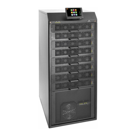
Figure 1: Major components of the Centric (200 and 100 kW models)................................................4
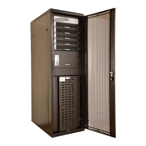
Figure 2: Major components of the Centric (50 kW model)..................................................................5
Figure 3: System control panel, displaying the main menu..................................................................6
Figure 4: System control panel, with current navigation path ..............................................................6
Figure 5: The control panel, displaying the Main Screen...................................................................10
Figure 6: Location of fallback push-button control panel....................................................................12
Figure 7: Close-up of the push-button control panel..........................................................................12
Figure 8: The main screen and its features........................................................................................13
Figure 9: The Operation submenu .....................................................................................................15
Figure 10: The "Turn off / on" submenu.............................................................................................15
Figure 11: The system requests confirmation....................................................................................16
Figure 12: The "Turn off / on" submenu.............................................................................................16
Figure 13: The system requests confirmation.....................................................................................16
Figure 14: The Status screen.............................................................................................................17
Figure 15: Main menu, UPS off, normal mode...................................................................................20
Figure 16: Centric main menu............................................................................................................22
Figure 17: “Key” icon on function button ............................................................................................22
Figure 18: "Setup" menu ....................................................................................................................23
Figure 19: "Setup > SYSTEM" options...............................................................................................24
Figure 20: "Setup > Modules" options................................................................................................28
Figure 21: "Setup > Battery" options..................................................................................................30
Figure 22: "Setup > Static Switch" options.........................................................................................34
Figure 23: "Setup > Alarms" options ..................................................................................................36
Figure 24: "Setup > Connectivity" options..........................................................................................37
Figure 25: Setup > Connectivity > SNMP configuration options........................................................38
Figure 26: Creating a new community................................................................................................38
Figure 27: Community name accepted ..............................................................................................38
Figure 28: Defining serial communication parameters.......................................................................39
Figure 29: Defining Modbus communication parameters...................................................................40
Figure 30: Remote shutdown submenu .............................................................................................53
Figure 31: New shutdown destination................................................................................................54
Figure 32: Select the shutdown target and press the arrow...............................................................54
Figure 33: Remote shutdown menu with target destination added....................................................54
Figure 34: Shutdown destination screen............................................................................................55
Figure 35: Example of email message body......................................................................................55
Figure 36: The email configuration menu...........................................................................................56
Figure 37: “Add new recipient” line.....................................................................................................57
Figure 38: New email recipient screen...............................................................................................57
Figure 39: Alarms button on email recipient screen...........................................................................57
Figure 40: Alarm selection screen for email recipient........................................................................58
Figure 41: "Setup > Time" options......................................................................................................58
Figure 42: Assigning a site ID ............................................................................................................59
Figure 43: "Setup > Dry Contacts" option ..........................................................................................60
Figure 44: Defining an input dry contact.............................................................................................61
Figure 45: Example of an output dry contact linked to an alarm........................................................63
Figure 46: "Setup > Save & Restore" options....................................................................................64
Figure 47: "Setup > Authorization" option..........................................................................................65
Figure 48: The "Operation" option on the main menu........................................................................66
Figure 49: "Main Menu > Status" option.............................................................................................68
Figure 50: The Status Screen ............................................................................................................68
