Flexbar
21-1-2009
edda
Algemene installatie instructie
modifications
destination
Gamko Holding BV
Mon Plaisir 75
4879 AL Etten-Leur
Tel.(0)76-5087500
The Netherlands
name
drawing nr.
draftsman date
196169
1 02/09 DMX + CELS 5611
1 02/09 DMX + CELS 5611
Blad 9 van 13
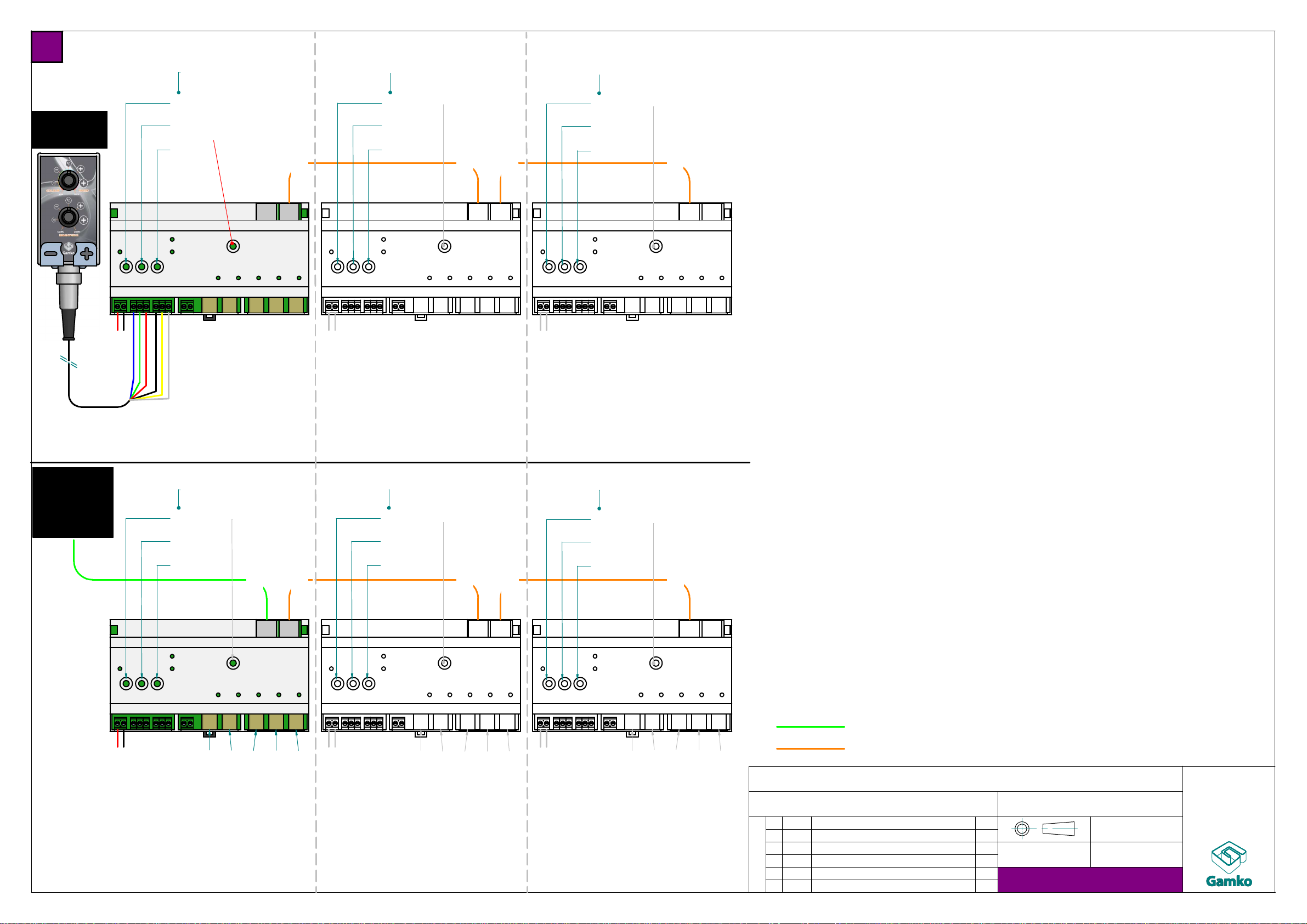
Driver Bar 1
(master) Driver Bar 2
(slave) Driver Bar 3
(slave)
Mode = 0
Mode = 0
1
0
0
Mode = 1
Mode = 0
1
0
0
1
0
0
6
1
0
1
0
0
1
0
0
Driver Bar 1
(slave 0)
LED output 1
(DMX R=001, G=002, B=003)
LED output 2
(DMX R=004, G=005, B=006)
LED output 3
(DMX R=007, G=008, B=009)
LED output 4
(DMX R=010, G=011, B=012)
LED output 5
(DMX R=013, G=014, B=015)
LED output 6
(DMX R=016, G=017, B=018)
LED output 7
(DMX R=019, G=020, B=021)
LED output 8
(DMX R=022, G=023, B=024)
LED output 9
(DMX R=025, G=026, B=027)
LED output 10
(DMX R=028, G=029, B=030)
LED output 11
(DMX R=001, G=002, B=003)
LED output 12
(DMX R=001, G=002, B=003)
LED output 13
(DMX R=001, G=002, B=003)
LED output 14
(DMX R=001, G=002, B=003)
LED output 15
(DMX R=001, G=002, B=003)
LED output 1
LED output 2
LED output 3
LED output 4
LED output 5
LED output 1
LED output 2
LED output 3
LED output 4
LED output 5
LED output 1
LED output 2
LED output 3
LED output 4
LED output 5
Mode = 0
24V DC
41
24V DC
24V DC 24V DC
24V DC 24V DC
DMX in
DMX out
DMX address 0-0-1 DMX address 0-0-1
DMX address 0-0-1
DMX address 0-1-6 DMX address 0-0-1
DMX address 0-0-1
Controller
Gamko
example:
Driver Bar 2
(slave 0)
example:
Driver Bar 3
(slave 1)
External
DMX-
device
(master)
DMX in
DMX out
DMX in
DMX out
DMX in
DMX out
DMX in
DMX out
DMX in
DMX out
RJ45-RJ45 Ethernet patch cable (Cat5e)
XLR-RJ45 connection cable (008110192)
Mode switch
(see list)
Default = 5
Gamko controller mode
X/ACLED1-A = mode 4 - manual colour lapse (master)
controller controls colour and brightness
X/ACLED1-B = mode 5 - automatic colour lapse (master)
controller controls cycle speed and brightness
Demo mode
X/ACLED1-C = mode 6 - different colour (static) per segment (master)
switch dmx address to 0-0-1 to select output nr1
use controller to set colour
switch dmx address to 0-0-2 to select output nr2
use controller to set colour
controller controls brightness
X/ACLED1-D = mode 7 - chasing light RGB (master)
dmx address 0-0-1 fast cycle speed
dmx address 9-9-9 slow cycle speed, etc.
controller controls brightness
X/ACLED1-F = mode 8 - chasing light rainbow (master)
dmx address 0-1-0 slow colourchange
dmx address 9-9-0 fast colourchange, etc.
controller regelt intensiteit
Slave mode
X/ACLED1-E = mode 0 - DMX15 (each segment individual) (slave)
to synchronise colours of 2nd, 3rd, etc bars
with first bar (master)
or to manipulate colours with lighting computer
no controller
X/ACLED1-E = mode 1 - DMX3 (all segments equal) (slave)
to synchronise colours of 2nd, 3rd, etc bars
with first bar (master)
or to manipulate colours with lighting computer
no controller
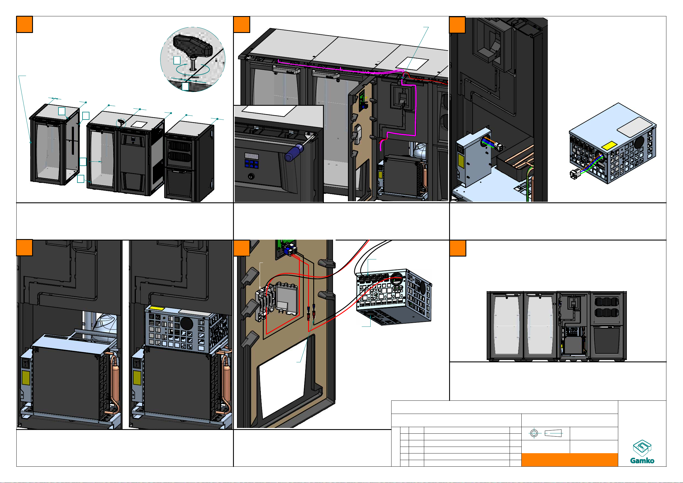
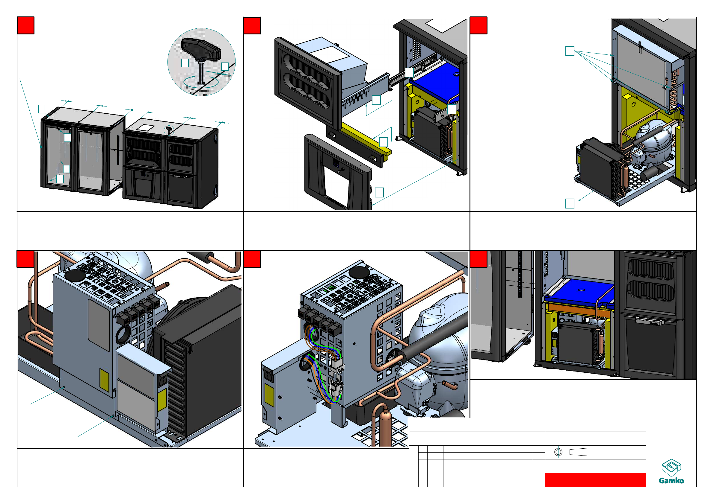
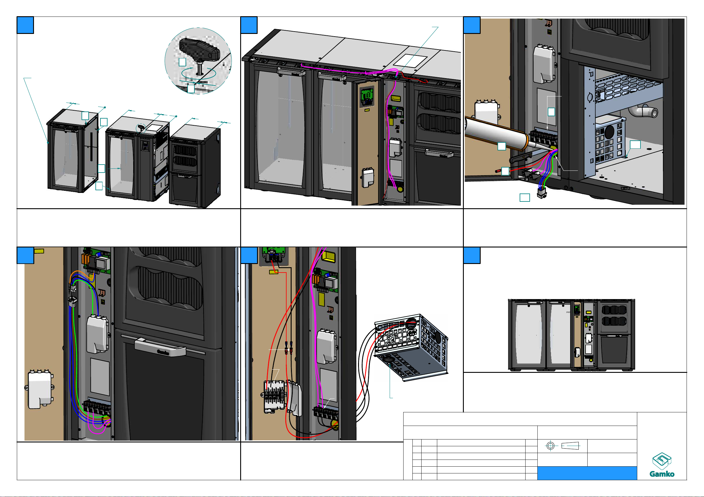
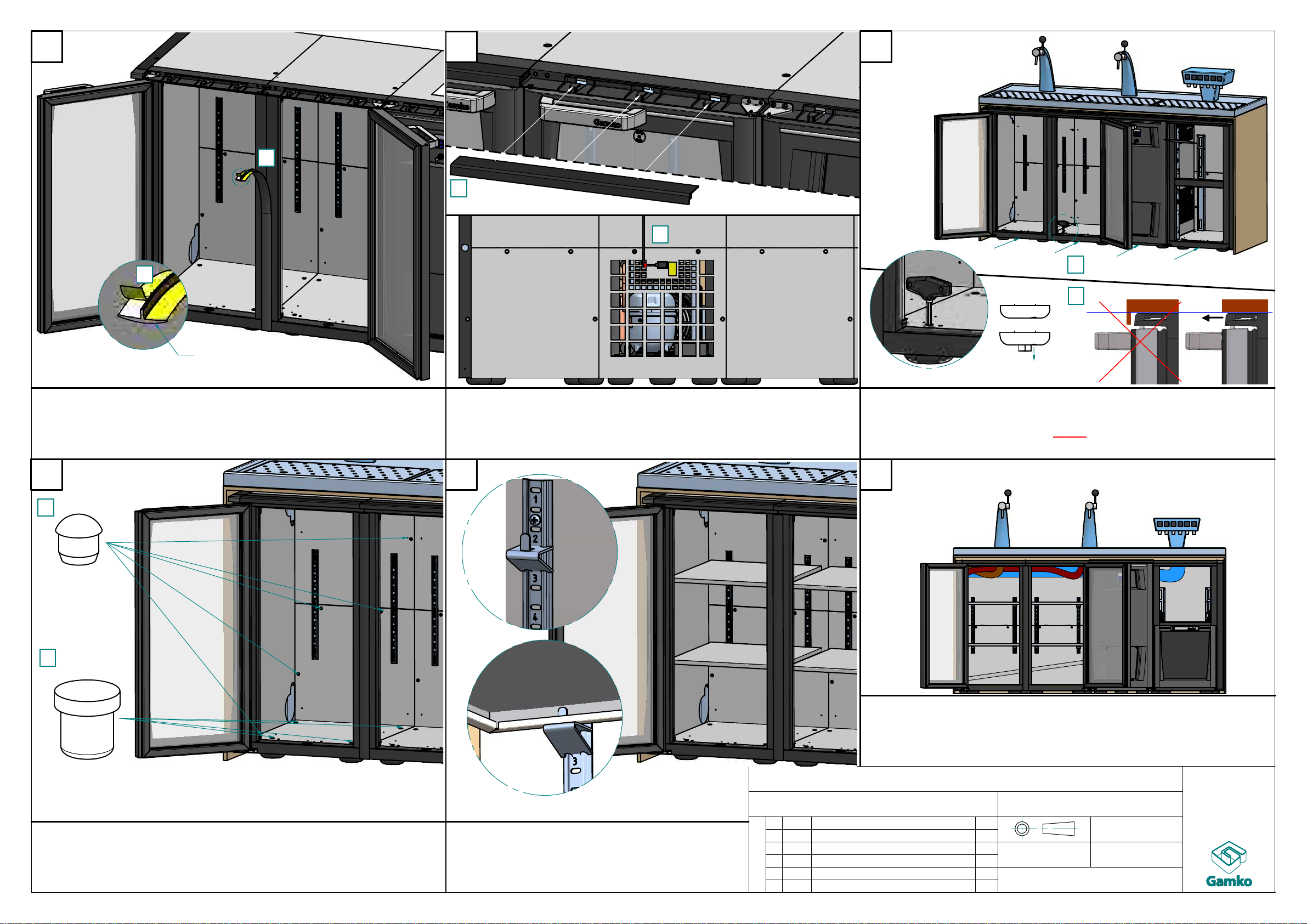
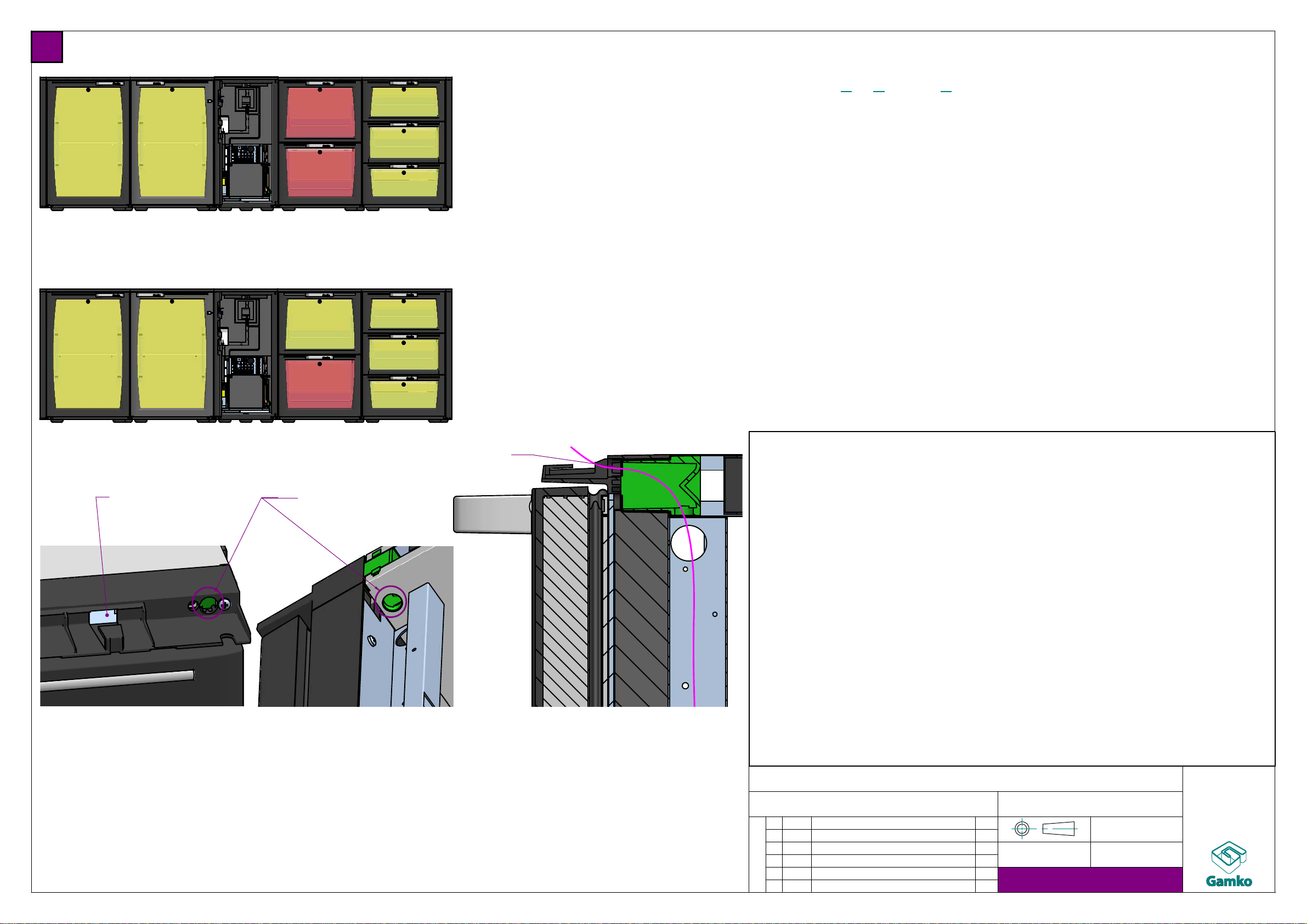
Connecting and settings
RGB driver(s)
GB
RGB settings