Gamma Sports 602FC User manual

GAMMA SPORTS
200 Waterfront Drive
Pittsburgh, Pennsylvania 15222
Phone : 800.333.0337 Fax : 412.323.0317
Visit our website at www.gammasports.com
Copyright 2012 GAMMA Sports - All Rights Reserved
MMAN-32
(MP62F-12)
OWNER'S MANUAL
Issue 6 - November 2012
602FC
STRINGING MACHINE

2 15
SBSQ T B
PARTS DRAWING
5
MCFCT
14
MMSPP13
381
133
21A
189
187
188
4A
8
9
6A
9
6A
190
284
144
356
140
357
141
146A
271
MQAC11
10B
MFSPP11
MRSG
29
28
27
25
26
31
30A
83
30
162
163
161
35
34
262
MBMSP11
268
261 267

14
MBFS11 BADM FRAME SUPPORT
MBMSS11 BADM MOUNTING SYS UPG
MBFC BADM FLOATING CLAMP
MDCSC BADM FIXED CLAMP
MPG STARTING CLAMP
MPMC MACHINE COVER
MPS CLEANING STONE
MPXFS FLOOR STAND
SGSM STRINGER’S MAT
PARTS LIST
4A TURNTABLE BUSHING
5 RUBBER FOOT
6A CAP SCREW- M8x25
8 BUSHING SET SCREW
9 WASHER- M8
10B WINDER STAND
14 WASHER- M10
21A FRAME SUPPORT SLIDE
25 TENSION BAR
26 TENSION BAR CAP
27 DROP WEIGHT KNOB
28 FRONT WEIGHT- BADMINTON
29 BACK WEIGHT
30 TENSION BAR DRUM
30A SET SCREW
31 STRING GRIPPER DRUM
34 RATCHET TEETH
35 RATCHET SPRING
83 TENSION BAR STOP SCREW
133 FRAME SUPP SLIDE SCREW
140 MTNG STAND TOP PLATE
141 MTNG STAND TOP PAD
144 SHLDER SUPP LOCK KNOB
146A SUPP ARM ADJUST KNOB
161 WINDER BEARING
162 GRIPPER PIVOT PIN
163 PIVOT PIN RETAINING COLLAR
187 PII BASE
188 PII BASE COVER
189 PII LOWER TRAY PAD
190 PII UPPER TRAY PAD
261 TT END CAP
262 SUPP POST MOUNTING PLATE
267 TT END CAP- RIGHT
268 TT END CAP- LEFT
271 SUPPORT POST
284 3 PIECE TURNTABLE
356 QM ARM (LONG) RIGHT
357 QM ARM (LONG) LEFT
381 SHOULDER V-MOUNT
71 6MM T-AHNDLE HEX WRENCH*
98 10MM WRENCH*
108 UTILITY KNIFE*
109 NEEDLE NOSE PLIERS*
110 BENT NOSE PLIERS*
196 17MM SOCKET*
251 HEX WRENCH SET*
MA STRINGER’S AWL*
MPSA PATHFINDER AWL*
MFSPP11 FRAME SUPP PADS
SHORT BADMINTON (SB)
SQUASH (SQ)
TENNIS (T)
BADMINTON (B)
MMSPP13 V-MOUNT SUPP PAD
MBMSP11 BADM SHOULDER SUPP COVER
* (NOT SHOWN)
OPTIONAL TOOLS & ACCESS
PART # DESCRIPTION
TOOLS & ACCESSORIES
MCFCT COMP. FIXED TENNIS CLAMP
MQAC11 QUICK ACTION BASE- TALL
MRSG ROTATIONAL GRIPPER
PART # DESCRIPTION
3
LIMITED WARRANTY
GAMMA SPORTS ("GAMMA") warrants to the original purchaser that the GAMMA PROGRESSION stringing machine
("EQUIPMENT") purchased is free from defects in materials and workmanship for a period of five (5) years from the date of
original purchase for mechanical parts (excluding electrical parts and string clamps) and for a period of one (1) year from the
date of purchase for all electrical parts and string clamps. Should any defects develop under normal use within the specified
time periods, GAMMA will at its option, repair or replace the defective EQUIPMENT provided it is returned to GAMMA prepaid
at the purchaser's expense. This warranty does not apply to any damage or defect caused by negligence, abuse, misuse,
unauthorized alteration, shipping, handling or part wear and tear as a result of normal use.
GAMMA's obligation under this warranty is limited to repair or replacement of defective EQUIPMENT, and no one is authorized
to promise any other liability. GAMMA shall in no event be liable for any incidental or consequential damages.
To return defective EQUIPMENT, a return authorization (RA#) must be obtained from a GAMMA customer service representa-
tive by calling 1-800-333-0337. The RA# must be marked on the outside of the shipping carton being returned. All returns
must be shipped prepaid by the customer to GAMMA. Please retain the original shipping carton and packing materials for
any future shipments. GAMMA will not be responsible for machines which are not sent in the original undamaged packaging.
A GAMMA Care Service Plan is also available through GAMMA customer service, call 800.333.0337 for details.
TABLE OF CONTENTS
WARRANTY ................................................................................................ PAGE 3
FEATURES.................................................................................................. PAGE 4
ASSEMBLY INSTRUCTIONS ..................................................................... PAGE 5
MOUNTING THE FRAME ...........................................................................PAGE 5
STRINGING THE FRAME........................................................................... PAGE 7
PATHFINDER AWL.................................................................................... PAGE 11
MAINTENANCE ........................................................................................ PAGE 12
TROUBLESHOOTING TIPS ..................................................................... PAGE 13
PARTS LIST ............................................................................................. PAGE 14
PARTS DRAWING..................................................................................... PAGE 15
602FC
OWNER’S MANUAL

4
FEATURES
MACHINE FEATURES
Drop Weight Tensioner with 9 to 90 lbs range and Permanently
Engraved Weight Scale
Patented Parallel Jaw Rotating Ratchet Gripper with Diamond
Dust Coated Gripping Surfaces
Professional Six Point “Quick Mount” Racquet Mounting System-
Accommodates All Racquets
Professional “Quick Action” Dual Action, Rotating, Composite
Fixed String Clamps with Diamond Dust Coating
Durable Polystyrene Base Cover with Convenient Padded Tool
Tray
Strong, Light Weight, Aluminum Construction
13
CARE & CLEANING
With time and use, the clamping surfaces of your machine may become oily or dirty and result
in string or clamp slippage while stringing. Periodic cleaning of the String Clamps, String Clamp
Base and String Gripper is recommended. Knife sharpening stones work well for cleaning the
diamond coated string clamping surfaces. Cleaning with a solvent such as isopropyl alcohol
and a mild abrasive tool such as a toothbrush also works well to remove oily or greasy build up.
PROBLEM SOLUTION
String slips in clamps - Adjust gap between clamp jaws
- Clean clamp jaws
String slips in gripper - Clean gripper jaws
- Make sure string is wrapped over top gripper
prior to inserting between gripper jaws
String clamp base slips on turntable - Clean bottom of clamp & top of turntable with
alcohol
- Adjust clamp base locking nut
TROUBLESHOOTING TIPS

12
Adjusting the Clamp Pressure
The clamps provided with your stringing ma-
chine will need minor adjustments according
to what string type, construction, and gauge
you are using.
To adjust the gap (clamping pressure)
between the clamp jaws, insert the string
through the racquet as if you were beginning
the main strings. Clamp the strings and pull
tension. If the string slips through the jaws of
the clamp, tighten the clamp by compress-
ing the clamp jaws together by hand while
turning theAdjustment Knob, in the clockwise
direction. If the clamp leaves impressions
or damages the string, it may be excessively tight and should be adjusted by turning the
hex screw counter clockwise to open the gap between the jaws. The clamp jaws should be
cleaned periodically to be free from dirt, oil, and any string coating for them to grip properly.
Note: The string clamps supplied with your stringing machine can accommodate tight string
patterns such as badminton. Depending on the string pattern, the clamp may spread the
strings slightly which will not compromise the quality of the string job.
Adjusting the Turntable Bushings
There are two adjustment points on the
machine base. One is located beneath the
polystyrene base cover while the other is
accessed from below the machine.
Using the supplied 3mm hex wrench, tighten
both set screws slightly until the turntable
rotates smoothly without excessive free play.
Repeat procedure until final adjustment is
reached.
MAINTENANCE & ADJUSTMENTS
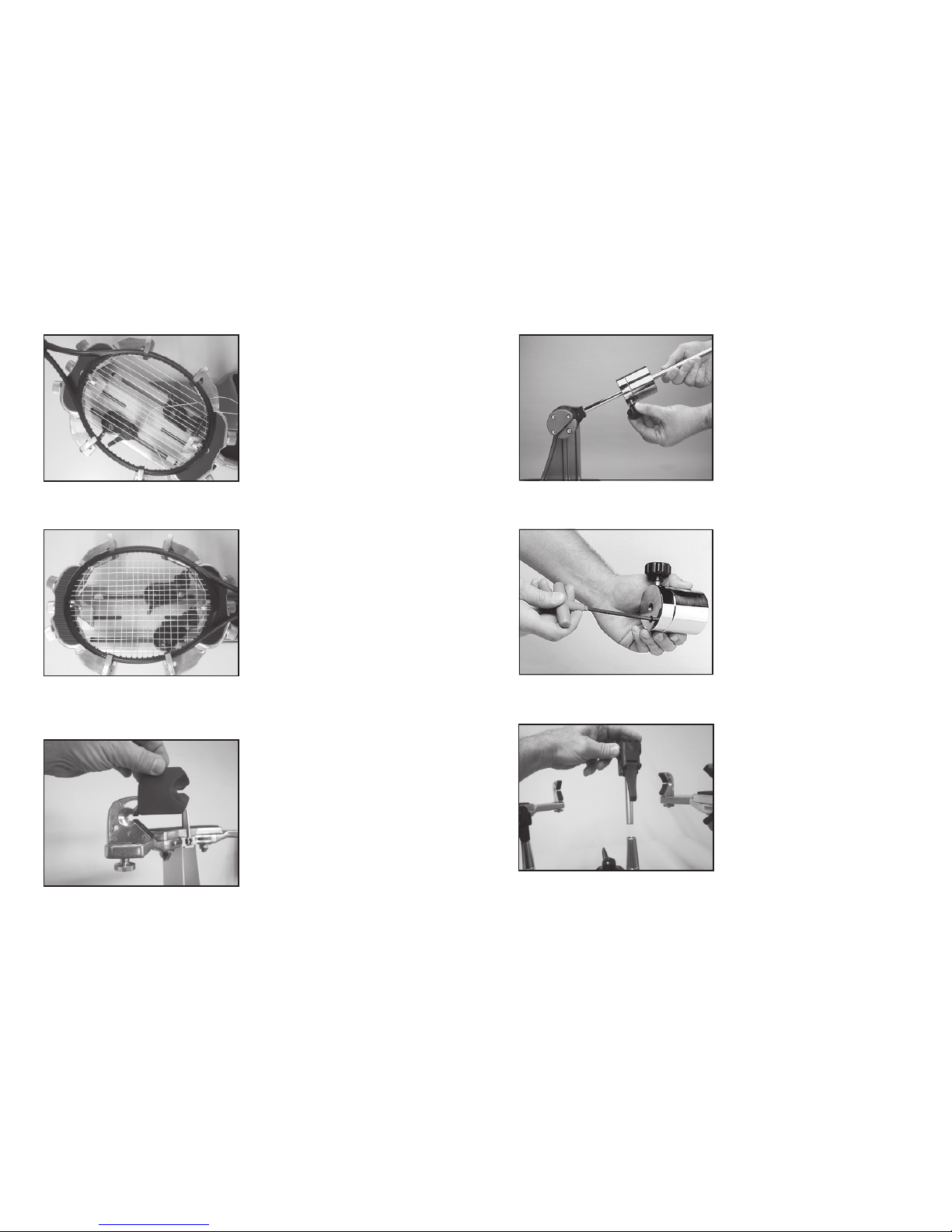
Adjustment
Knob
Clamp Base Locking NutAdjustment
In the event the Locking Lever rotation is
insufficient to ensure smooth operation of the
clamp base, very minor adjustments to the
Clamp Base Locking Nut can be made with
the supplied 17mm socket. Tighten or loosen
the locking nut in very small increments to
provide more clamping pressure or running
clearance as needed.
5
ASSEMBLY INSTRUCTIONS
Engaging the Drop Weight Bar Stop
The stringing machine is shipped with the
drop weight bar in the horizontal position.
To prevent racquet damage during stringing,
the bar stop must be engaged.
Remove the machine base from the shipping
carton being careful to avoid lifting by the
plastic cover.
Hold the drop weight bar in the vertical posi-
tion as shown while turning the stop screw
clockwise with the supplied 5mm hex wrench.
String Clamp Installation
The post of the string clamp head and tube of
the string clamp base are treated with grease
to provide protection against corrosion during
shipping. Remove any excessive grease with
a clean cloth prior to use. The post and tube
may also be cleaned with isopropyl alcohol.
After this type of thorough cleaning, the post
and tube should be treated with a light coating
of machine oil to protect the surfaces against
corrosion and to ensure smooth operation.
MOUNTING THE FRAME
Adjusting the Frame Support Posts
Place the racquet frame over the center
posts and onto the frame support. Loosen the
lever lock bolt on one support post. Slide the
post outward until the center support of the
racquet support slide is positioned near the
inside surface of the racquet frame. Securely
tighten the lever lock bolt.
Adjust the opposite post using the same
procedure.
Caution: To avoid racquet damage, the
center posts should not contact the racquet
prior to fixing the support posts.

6
Frame Shoulder Support Arm
Adjustment
Being sure the shoulder supports are free
to swivel in their mountings, simultaneously
rotate the shoulder support adjustment knobs
clockwise until both shoulder supports gently
and squarely contact the frame.
The shoulder supports are designed to rotate
and can be adjusted to provide maximum
support to the racquet frame. Rotate the
support so that the pads contact the frame
squarely when the arms are closed against
the racquet.
Tightening the Center Supports
Tighten the Center Supports by turning
the adjustment knob clockwise until slight
resistance is felt.
Caution: Overtightening the Center Supports
may cause racquet damage.
Securing the Frame
Lock the shoulder supports in position by
turning the knob at the base clockwise.
Repeat the adjustment procedure for the
remaining support post.
Re-tighten all of the frame supports in the
same order as before.
Do not overtighten any of the supports as
racquet damage may occur.
The supports should be tightened to the point
where the racquet frame will not move in the
mounting system when the handle is grasped and attempts are made to move it. Should any
supports lose contact with the frame while stringing, they should be re-tightened.
MOUNTING THE FRAME
11
PATHFINDER AWL
Once the awl is inserted, pull the handle of
the awl outward while holding the tip section
in place. This leaves the outer sheath in the
grommet hole. Insert the end of the string
into the outer sheath.
While holding the string, slowly pull the sheath
out of the grommet hole to leave the free end
of the string exposed.
The machine includes the pathfinder string-
ing awl which creates a pathway between
or around strings to make inserting a string
through blocked grommets easier and
quicker.
Insert the awl through the grommet hole in
the same manner as for traditional awls. The
Pathfinder awl must be in the closed position
before insertion.

10
STRINGING THE FRAME
Weaving the Cross Strings
Weave the cross strings over and under the
main strings being careful to alternate the
weave direction of each consecutive cross
string so as to be opposite of the previously
installed cross string.
Once the final cross string is tensioned and
clamped, tie off at the appropriate hole speci-
fied by the racquet manufacturer.
ADDITIONAL FEATURES
Badminton Shoulder Support Pad
Installation
Slide the badminton shoulder support cover
over the shoulder supports. There is no need
to remove the tennis shoulder supports.
Note: An optional badminton frame support
for the head of the racquet is available.
7
Fixed Clamp Operation
The fixed clamps are of a dual action design.
The string clamp and the clamp base operate
independently of one another.
To clamp a string, lift the clamp head and
place the string between the jaws. Depress
the clamp head lever to secure the string.
The clamping pressure applied to the string
should be adjusted to provide sufficient pres-
sure to secure the string when subjected to
the desired pulling tension.
The diamond coated gripper plates provide
for increased friction between the clamps and the string to allow for reduced clamping pres-
sure while securing and holding the string under tension.
Note: If the string slips in the string clamp while tensioning, adjust the gap between the clamp
jaws as per the instructions on page 12.
STRINGING THE FRAME
The drop weight is of a two piece design.
When assembled, it will accommodate ten-
sions from 20 to 90 lbs. For tensions from 8
to 20 lbs., remove the 5mm bolt on the face of
the drop weight, and use the smaller portion
of the weight as described above.
Note: Tensions above 77lbs. require removal
of the drop weight bar end cap.
Setting Tension
To set the stringing tension, loosen the
locking knob on the side of the drop weight.
Slide the weight in the appropriate direction
until the face closest to the string gripper is
indexed with the desired tension mark on
the tension bar.

8
Gripping the String
While holding the tension bar slightly above
horizontal, wrap the free string clockwise
around the gripper drum once and position
between the gripper jaw.
Gently turn the gripper clockwise while
squeezing the jaws together until all slack
in the string is removed.
Note: For proper operation, the string grip-
per jaw must be in the position shown. The
tension in the string provides the clamping
force to the jaws.
Getting Started
To begin stringing the main strings, thread
the two ends of the string through the two
center holes at the appropriate end of the
frame and continue through the opposite
center holes. Thread one end of the string
through the adjacent grommet hole and pull
excess by hand.
Secure one of the strings using a string clamp.
Handy tip: The tear drop shaped holes
towards the back of the shoulder supports
are handy for holding the loose end of the
string while tensioning the string. Simply insert the loose end into the tear drop shaped holes
and slide the string toward the point of the hole.
Base Clamp Operation
Rotate the lever lock clockwise to secure
the clamp base to the turntable.
Reverse the clamping procedure to unlock
the string clamp.
The lever should be tightened enough to
prevent clamp base slippage on the turn-
table, when the desired tension is placed
on the string. To go from the loose position
to the clamped position and back, gener-
ally requires about 1/2 to 3/4 quarters of a turn. Although when stringing at extremely high
tensions, additional tightness may be required.
STRINGING THE FRAME
9
STRINGING THE FRAME
WARNING: TO AVOID INJURY, KEEP FINGERS AWAY
FROM GRIPPER JAWS WHILE TENSIONING STRING.
Pulling Tension
While securely holding the string gripper drum
with your hand, lift the tension bar above
horizontal and gently lower the bar under its
own weight. If the tension bar drops below
horizontal, repeat the above action until the
bar comes to rest parallel to the racquet.
When the correct tension is attained, the drop
weight bar will rest horizontally as shown. For
accurate tensioning, it must be lowered and
come to rest at horizontal without assistance.
Manually forcing the tension bar to the hori-
zontal position will greatly increase the string
tension and may result in racquet damage.
If the tension bar comes to rest above hori-
zontal, release the string by lifting the bar
and re-pull the string.
Clamping the First Main String
Secure the tensioned main string using the
second fixed clamp. Repeat the procedure
for all of the remaining main strings and tie off
at the appropriate hole following the racquet
manufacturers specification.
Follow the racquet manufacturer's recom-
mended stringing pattern for one or two piece
stringing. This will determine the starting
point for the cross strings. If applicable, tie
the first cross string using an appropriate
starting knot.
Table of contents
Other Gamma Sports Stringing Machine manuals