16
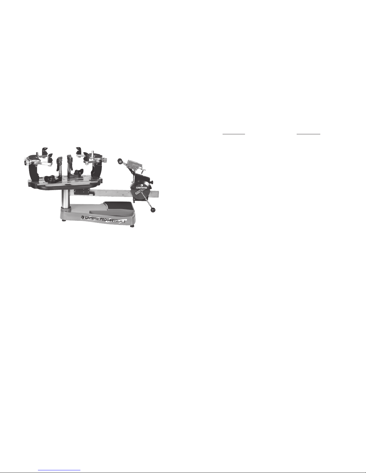
Adjusting the String Clamp Jaw
Spacing
The string clamps will need minor adjust-
ments according to what string type, construc-
tion, and gauge you are using.
To adjust the gap (clamping pressure)
between the clamp jaws, insert the string
through the racquet as if you were begin-
ning the main strings. Clamp the strings
and pull tension. If the string slips through
the jaws of the clamp, tighten the clamp
by squeezing the clamp jaws together by
hand while turning the Adjustment Knob, in
the clockwise direction. If the clamp leaves
impressions or damages the string, it may be excessively tight and should be adjusted by
turning the Adjustment Knob counter clockwise to open the gap between the jaws. The clamp
jaws should be cleaned periodically to be free from dirt, oil, and any string coating residue
to grip properly. Knife sharpening stones are excellent for removing build-up on the diamond
coated surfaces and are available.
Adjustment
Knob
MAINTENANCE & ADJUSTMENTS
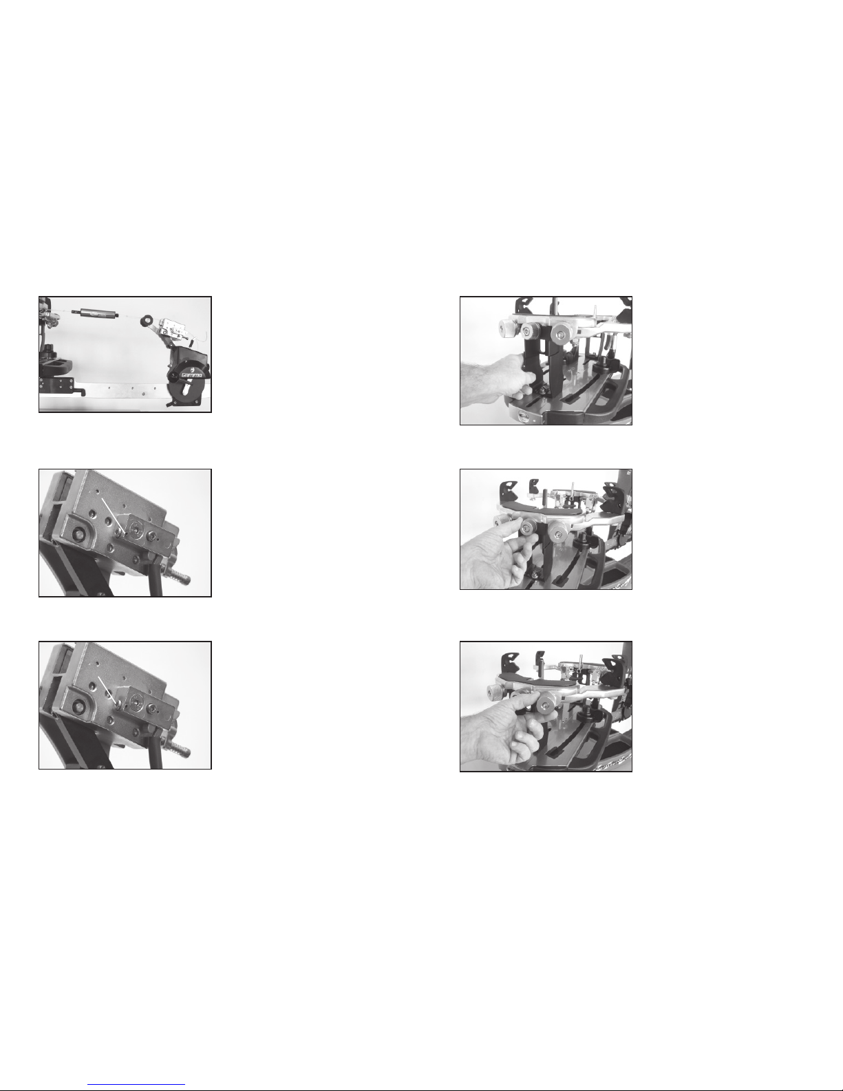
Clamp Base Locking NutAdjustment
In the event the Locking Lever rotation is
insufficient to ensure smooth operation of the
clamp base, very minor adjustments to the
Clamp Base Locking Nut can be made with
the supplied 17mm socket. Tighten or loosen
the locking nut in very small increments to
provide more clamping pressure or running
clearance as needed.
Quick Action Clamp Base Removal
Quick Action clamp bases can be removed
from the turntable for maintenance or cleaning
by removing clamp stop located at the end
of the slot in the turntable. To remove the
clamp stop, remove the two screws holding
the clamp stop in place from the underside of
the turntable. Lift the clamp stop out of the
slot, slide the clamp base to the end of the
slot and lift it out. Replace the clamp base
and clamp stop in reverse order.
5
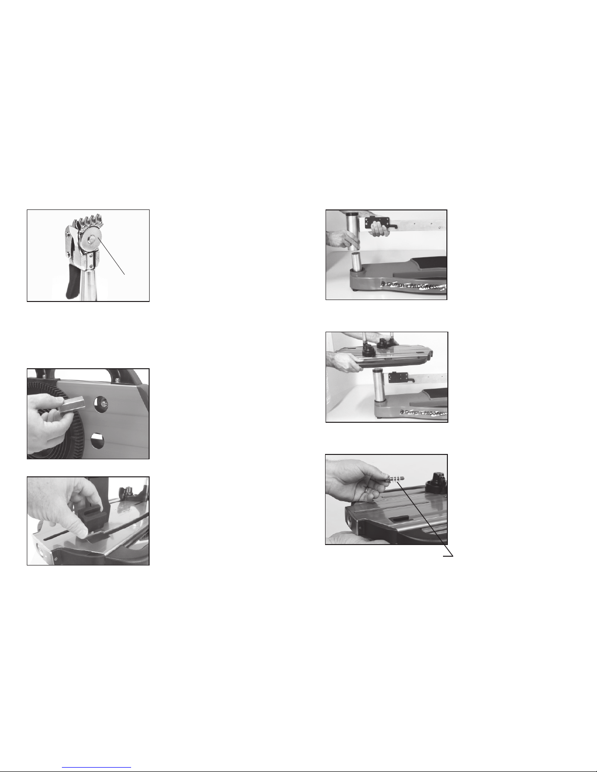
Support Post Installation
To install the support posts you must first
remove the mounting bolt from the mounting
plate that sets inside the central cavity of the
turntable. There are large holes stamped on
the underside of the turntable that allow you
to support the mounting plate with your fingers
while removing the mounting bolt.
After removing the mounting bolt, remove
and discard the plastic washers that are
installed for shipping purposes.
Remove and Discard Plastic Washers
ASSEMBLY INSTRUCTIONS
Turntable Installation
To install the turntable position it over the
turntable pin and align the bolts (included in
separate bag) with the holes in the flange.
Secure them with the included 6mm allen
wrench.
Winder Bar Installation
To install the winder bar, slide over the post
on the base and secure it with the 2 allen
set screws.
Note: When purchased with the optional floor
stand, it is most convenient to attach the base
to the floor stand at this point. See instruc-
tions provided with the optional floor stand.