Gamma Sports Els User manual

GAMMA SPORTS
200 Waterfront Drive
Pittsburgh, Pennsylvania 15222
Phone: 800.333.0337 Fax: 412.323.0317
Visit our website at www.gammasports.com
Copyright 2012 GAMMA Sports - All Rights Reserved
MMAN-30
(MPELS-12)
OWNER’S MANUAL
Issue 3 - November 2012
Els
STRINGING MACHINE

2
Els
OWNER’S MANUAL
LIMITED WARRANTY
GAMMA Sports (GAMMA) warrants to the original purchaser that the Progression Els stringing machine (“EQUIPMENT”)
purchased is free from defects in materials and workmanship for a period of five (5) years from the date of original purchase
for mechanical parts and for a period of one (1) year from the date of purchase for all electrical parts and string clamps.
Should any defects develop under normal use within the specified time periods, GAMMA will at its option, repair or replace
the defective EQUIPMENT provided it is returned to GAMMA prepaid at the purchaser’s expense. This warranty does not
apply to any damage or defect caused by negligence, abuse, misuse, unauthorized alteration, shipping, handling, or part
wear and tear as a result of normal use.
Routine maintenance, adjustment, and cleaning required to ensure proper operation are the responsibility of the purchaser and
are not covered under the terms of this warranty. These include, but are not limited to: String Clamp adjustment, as described
on page 16, Quick Action Clamp Base adjustment, as described on page 16 and the cleaning procedures listed on page 17.
GAMMA’s obligation under this warranty is limited to repair or replacement of defective EQUIPMENT, and no one is authorized
to promise any other liability. GAMMA shall in no event be liable for any incidental or consequential damages.
To return defective EQUIPMENT, a return authorization (RA#) must be obtained from a GAMMA customer service representa-
tive. The RA# must be marked on the outside of the shipping carton being returned. All returns must be shipped prepaid by
the customer to GAMMA. Please retain the original shipping carton and packing materials for any future shipments. GAMMA
will not be responsible for machines which are not sent in the original undamaged packaging.
A GAMMA Care Service Plan is also available through GAMMA customer service, call 800.333.0337 for details.
TABLE OF CONTENTS
WARRANTY ................................................................................................ PAGE 2
FEATURES.................................................................................................. PAGE 3
ASSEMBLY INSTRUCTIONS ..................................................................... PAGE 4
POWER CONNECTION & CONTROLS ..................................................... PAGE 5
MOUNTING THE FRAME ...........................................................................PAGE 7
STRINGING THE FRAME........................................................................... PAGE 9
ADDITIONAL FEATURES ......................................................................... PAGE 12
PATHFINDER AWL.................................................................................... PAGE 13
CALIBRATION............................................................................................PAGE 14
MAINTENANCE & ADJUSTMENTS .........................................................PAGE 15
TROUBLESHOOTING TIPS ..................................................................... PAGE 16
NOTES ...................................................................................................... PAGE 17
PARTS LIST ............................................................................................. PAGE 18
PARTS DRAWING..................................................................................... PAGE 19
19
PARTS DRAWING
360
365
334
321
320
373
289
327
328
329
285 283
286
270
96A
MDCSC13
MQAC12
MMSPP13
372
366
364
368
E76
MRSGD
144
5
MFSPP13
363
370
371
367
MBMSP13
369

18
MMP11-16 #324 FOOT PEDAL SWITCH
MBFC BADM FLOATING CLAMP
MBFS-14 BADM HEAD FRAME SUPP
MBMSS-11 BADM MOUNTING SYS UPG
MGSMC MACHINE COVER
MPG STARTING CLAMP
MPS CLEANING STONE
MPXFS FLOOR STAND
MTC CALIBRATOR
SGSM STRINGER’S MAT
PARTS LIST
5 RUBBER FOOT
6A CAP SCREW- M8x30
9 WASHER- M8
144 SHOULDER SUPP KNOB
203 TT BOLTS*
270 SUPP POST MOUNT PLATE
283 TT END CAP
285 TT END CAP- RIGHT
286 TT END CAP- LEFT
289 TT HANDLES
320 BRAKE RING
321 BRAKE BOX
327 TT PIN
328 TENSIONER
329 GRIPPER DRUM
334 BASE
360 TURNTABLE TT7
363 A220 MOUNTING STAND
364 A220 MNTG ARM (R)
365 A220 MNTG ARM (L)
366 A220 TOP PLATE
367 A220 TOP PLATE/ARM PADS
368 A220 ADJ KNOB & SCREW
369 A220 FRAME SUPP KNOB
370 ADJ KNOB RUBBER GRIP
371 A220 SHOULDER V-MNT BLK
372 A220 FRAME SUPPORT
373 MPELS BASE COVER (RED)
E76 KEY PAD / ELECTRONICS
MDCSC13 UNIV DC STRING CLAMP
MRSGD DIE CAST GRIPPER
MQAC12 QA BASE CLAMP
71 6MM T-HANDLE HEX WRENCH*
109 NEEDLE NOSE PLIERS*
110 BENT NOSE PLIERS*
167 HEX WRENCH SET*
171 DIAGONAL CUTTERS*
196 17MM SOCKET*
E16 A/C POWER CORD*
E23 AC ADAPTER*
MA STRINGER’S AWL*
MFSPP13 FRAME SUPP PAD SET
6 FRAME PADS
2 BAD SLIDE ON “H” PADS
MMSPP13 TENNIS SHLDER SUPP PADS
MBMSP11 BAD SHLDER SUPP COVER
MPSA PATHFINDER AWL*
* (NOT SHOWN)
OPTIONAL TOOLS & ACCESS
PART # DESCRIPTION TOOLS & ACCESSORIES
3
MACHINE FEATURES
Electric Constant Pull Tensioner with 11.0 to 90.0 lbs Tension
Range
Digital Tension Setting with LED Display
Parallel Jaw Rotating Gripper with Diamond Dust Coated
Gripping Surfaces
Professional Six Point “Quick Mount” Racquet Mounting
System- Accommodates All Racquets
Professional “Quick Action” Dual Action, Rotating, Metal Fixed
String Clamps with Diamond Dust Coating
Durable Polystyrene Base Cover with Convenient Padded Tool
Tray
Strong, Light Weight, Aluminum Construction
Convenient Foot Actuated Tensioner Switch (Optional)
FEATURES

4
ASSEMBLY INSTRUCTIONS
String Clamp Installation
The post of the string clamp and tube of the
string clamp base are treated with grease to
provide protection against corrosion during
shipping. Remove any excessive grease with
a clean cloth prior to use. The post and tube
may also be cleaned with isopropyl alcohol.
After this type of thorough cleaning, the post
and tube should be treated with a light coating
of machine oil to protect the surfaces against
corrosion and to ensure smooth operation.
Transportation Screw
The machine has been shipped with a motor
and load cell protection screw. Remove the
screw before using the machine. Retain the
screw for future shipment. Install the included
rubber grommet into the hole.
Remove this Screw
17
NOTES

16
TROUBLESHOOTING TIPS
CARE & CLEANING
With time and use, the clamping surfaces of your machine may become oily or dirty and result
in string or clamp slippage while stringing. Periodic cleaning of the String Clamps, String Clamp
Base and String Gripper is recommended. Knife sharpening stones work well for cleaning the
diamond coated string clamping surfaces. Cleaning with a solvent such as isopropyl alcohol
and a mild abrasive tool such as a toothbrush also works well to remove oily or greasy build up.
PROBLEM SOLUTION
String slips in clamps - Adjust gap between clamp jaws
- Clean clamp jaws
String slips in gripper - Clean gripper jaws
- Make sure string is wrapped over top gripper
prior to inserting between gripper jaws
String clamp base slips on turntable - Clean bottom of clamp & top of turntable with
alcohol
- Adjust clamp base locking nut
Electrical system does not function - Check power source
- Check power cord connections
String tension too tight or too loose - Check tension using a tension calibrator,
adjust machine calibration if necessary
5
POWER CONNECTION & CONTROLS
Front Panel Features
A - String Gripper
B - Tension Switch
C - LED Tension Display
Back Panel Features
A - Lighted Power Switch
B - Foot Pedal Switch Receptacle
C - A/C Power Cord Socket
D - String Length Meter (currently not
available)
B
C
A
C
B
A
Instructions for Power Connection and Controls
CAUTION ! Before connecting to the power supply, check the voltage source that the
machine is being connected to. The acceptable range of input voltages for this ma-
chine is between 100 V and 240 V @ 50 to 60 Hz. If you have any questions regarding
the input voltage supply for your area, please ask your electric utility company.
To install the power cord, insert the female end of the power cord into the AC Adapter and
then insert the female end of the cord from the AC Adapter into the A/C Power Cord Socket
“C” located on the back panel of the tensioner. Plug the male end of the power cord into a
grounded power outlet. When using extension cords, use grounded heavy duty extension
cords rated for 15 AMP service.
To connect the foot pedal switch, insert the male pin at the end of the foot pedal switch cord
into the Foot Pedal Switch Receptacle “B” located on the back panel of the tensioner.
Switch on the machine by pressing the Lighted On-Off Power Switch on the back panel. At
start-up, the LED will display a countdown from “9.0” to “0.0” while the machine performs a
self diagnostics check at start-up.
D
WARNING! FOR INDOOR USE ONLY.
NEVER OPEN UNIT WITH POWER CONNECTED.
CHILDREN SHOULD NEVER BE PERMITTED TO OPER-
ATE THIS MACHINE WITHOUT ADULT SUPERVISION.

6
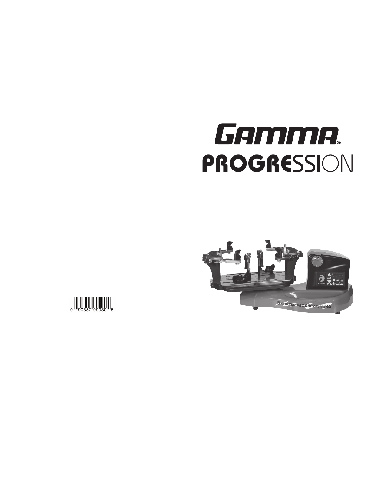
CONTROL PANEL FUNCTIONS
AND FEATURES
Single Digit (1-9)
Memory LED Display
Three Digit (XX.X)
Tension Setting Display
or String Length LED
Display
String Length Meter Button - feature is
currently not available.
Lbs/Kgs Button - Changes tension
display from Lbs to Kgs. Each press
of the button toggles back and forth
between Lbs and Kgs.
Speed Button - Changes pulling speed
of winder from Fast (default) to Medium
to Slow. Slow speed is recommended
for low stretch strings, such as Kevlar.
Each press of the button toggles be-
tween Fast, Medium and Slow speeds.
Pre-Stretch Function - Pulls string 10%
or 20% over the tension setting (up to 90
lbs / 40.8 kgs), releases the string, and
repulls to the tension setting. Each press
of the button toggles between 10%, 20%
or no pre-stretch.
Clear Button - Clears display to enter
a new tension or to reset String Length
Meter measurement.
Knot Function - Increases pulling ten-
sion by 10% over the setting value (max
90 lbs / 40.8 kgs) for one pull. During the
pull the LED stays lit to indicate the Knot
function is enabled.
Tension Index Buttons - Changes
tension setting in +/- 1.0 or +/- 0.1 Lb or
Kg increments. Holding the button down
will scroll the tension setting values up
or down. Tension settings entered with
the tension index buttons are placed into
temporary memory setting “0”.
Memory Button - Indexes from 9 preset
tension settings that can be stored in
memory. Settings are retained even if
machine is turned off. Each press of
the button indexes to the next memory
setting. Memory settings 1-9 must be
entered using the keypad followed by
pressing the “ENT” button.
Enter Button - Saves displayed tension
for Memory setting - when tension is en-
tered using the keypad display flashes
until this button is pressed to save the
setting. Also Clears display for String
Length Meter measurements.
Test Button & Racquet Strung -
Press once for approximate number of
racquets strung. Press again to return.
Press and hold for 5 seconds and the
machine does an internal diagnostic
check, such as the one performed at
start-up.
15
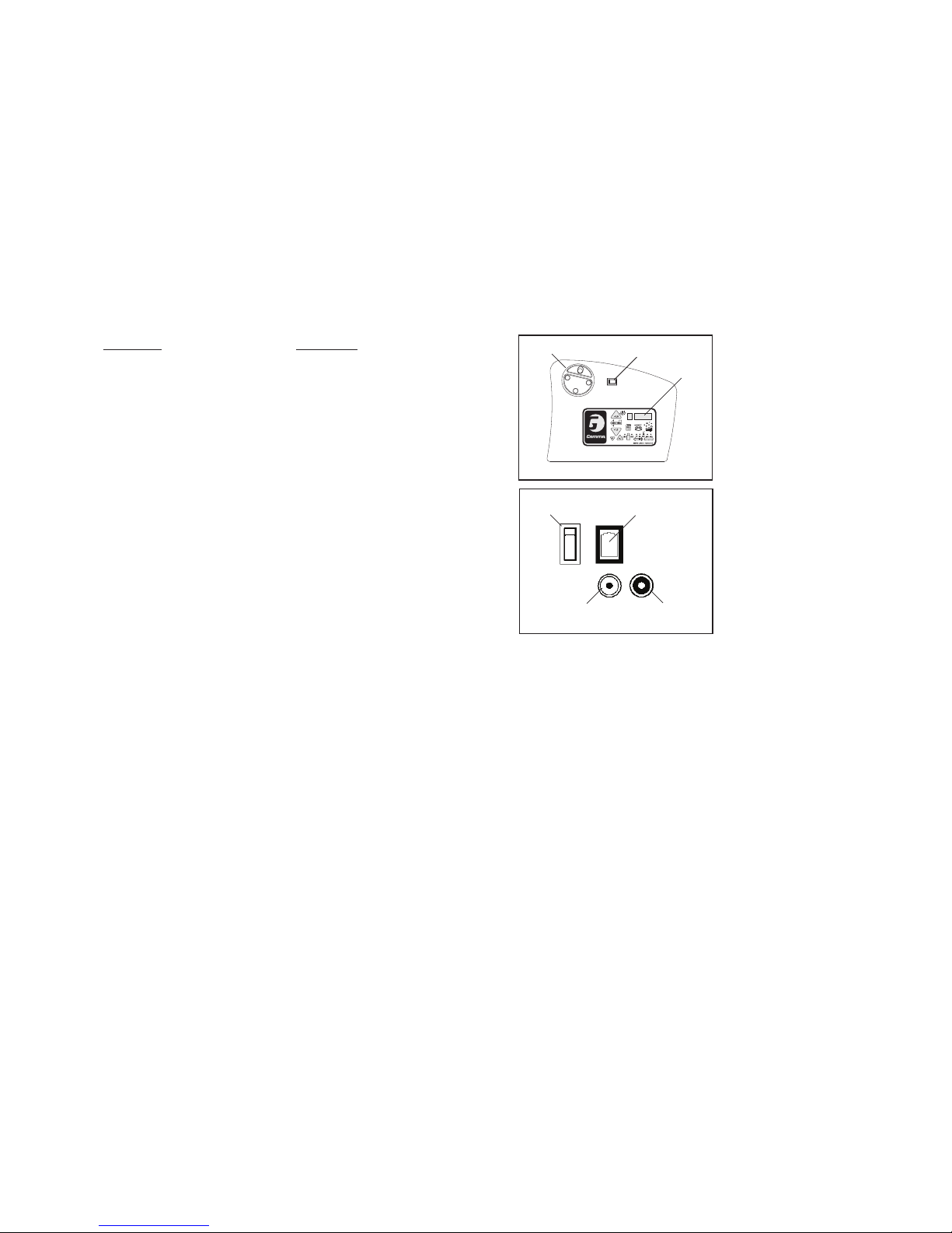
Adjusting the String Clamp Jaw
Spacing
The string clamps will need minor adjust-
ments according to what string type, con-
struction, and gauge you are using.
To adjust the gap (clamping pressure)
between the clamp jaws, insert the string
through the racquet as if you were begin-
ning the main strings. Clamp the strings
and pull tension. If the string slips through
the jaws of the clamp, tighten the clamp
by squeezing the clamp jaws together by
hand while turning the Adjustment Knob, in
the clockwise direction. If the clamp leaves
impressions or damages the string, it may be excessively tight and should be adjusted by
turning the Adjustment Knob counter clockwise to open the gap between the jaws. The clamp
jaws should be cleaned periodically to be free from dirt, oil, and any string coating residue
to grip properly. Knife sharpening stones are excellent for removing build-up on the diamond
coated surfaces and are available.
Adjustment
Knob
MAINTENANCE & ADJUSTMENTS
Clamp Base Locking NutAdjustment
In the event the Locking Lever rotation is
insufficient to ensure smooth operation of the
clamp base, very minor adjustments to the
Clamp Base Locking Nut can be made with
the supplied 17mm socket. Tighten or loosen
the locking nut in very small increments to
provide more clamping pressure or running
clearance as needed.
Quick Action Clamp Base Removal
Quick Action clamp bases can be removed
from the turntable for maintenance or clean-
ing by removing clamp stop located at the
end of the slot in the turntable. To remove the
clamp stop, remove the two screws holding
the clamp stop in place from the underside of
the turntable. Lift the clamp stop out of the
slot, slide the clamp base to the end of the
slot and lift it out. Replace the clamp base and
clamp stop in reverse order.

14
CALIBRATION
Tension Calibration Procedure
Each stringing machine has been
checked and calibrated at the factory
using accurate load sensing devices
to ensure that the machine pulls at
the correct tension. However, if you
suspect that your machine may not
be pulling at the correct tension you
can check the pulling tension with
a calibrator and make adjustments
if needed.
Most tension calibrators (such as a Gamma Tension Calibrator) function by clamping off the
string attached to one the end of the calibrator and applying tension to the string located on
the opposite end of the calibrator. The tension measured by the calibrator will then display
the tension being applied to the calibrator by the machine. If the calibrator and tensioner do
not match then you can adjust the tensioner as follows:
(1) Turn the machine off and restart the machine while holding down the Test button until
the count down is complete. 22 lbs should appear on the display. (2) Apply tension to the
calibrator. (3) If the tension reading on the calibrator does not match the tension displayed on
the machine, use the tension indexing buttons to match the display to the calibrator reading
and press the Enter/Clear button (4) Release the tension applied to the calibrator and 44 lbs
should appear on the display. (5) Repeat steps #2-#4 for 44, 66 & 88lbs. (6) After completing
the adjustment at 88lbs the display will show 00 lbs. (7) Restart the machine without holding
any buttons and the calibration adjustment will be complete.
Switching the Buzzer Off and On
The stringing machine is equipped with a buzzer that sounds when any key or button is
pressed or when there is a problem with some function of the machine. The buzzer can be
disabled if desired for normal keypad entries.
To disable the buzzer, turn the machine on and while the display is counting down from 9 to
0, press and hold the Enter/Clear button for at least 5 seconds. The buzzer will be disabled
and will remain disabled. It can be enabled again by following the same steps listed above.
Note: Even when disabled, the buzzer will sound if the tensioner has a problem and the
machine requires attention. This is meant to alert the user of a problem, and can not be
disabled.
7
MOUNTING THE FRAME
Frame Shoulder Support Adjustment
Being sure the shoulder supports are free to
swivel in their mountings, simultaneously rotate
the shoulder support adjustment knobs clockwise
until both shoulder supports gently and squarely
contact the frame.
Adjusting the Frame Mounting
Stands
Loosen the lock bolts of the frame support
posts and space them apart with the frame
support slides separated by the approximate
length of the racquet head. Although it is not
required, it is good practice to center the sup-
port posts on the turntable. Lock one of the
posts in position by tightening the lock bolt and
position the other post until the frame support
slide is positioned near the inside surface of
the racquet frame. Securely tighten the lock
bolt of the second support post.
Caution: To avoid racquet damage, the center posts should not contact the racquet prior to
locking down the support posts.
Tightening the Frame Supports
Tighten the Frame Support Slides by turn-
ing the adjustment knob clockwise until
snug against the racquet frame and slight
resistance is felt.
Caution: Overtightening the Center Supports
will stretch the head of the racquet and could
cause racquet damage.

8
Securing the Frame Shoulder Clamps
Lock the shoulder supports in position by
turning the knob at the base clockwise.
Repeat the adjustment procedure for the
remaining support post.
Re-tighten all of the frame supports in the
same order as before.
Do not overtighten any of the supports as
racquet damage may occur.
The supports should be tightened to the point
where the racquet frame will not move in the
mounting system when the handle is grasped and attempts are made to move it. Should any
supports lose contact with the frame while stringing, they should be re-tightened.
MOUNTING THE FRAME
Frame Shoulder SupportAdjustment
The shoulder supports are designed to rotate
and can be adjusted to provide maximum
support to the racquet frame. Rotate the
support so that the pads contact the frame
squarely when the arms are closed against
the racquet. Should the shoulder supports
block string holes, adjust the frame support
slides to re-position the racquet between the
arms so the shoulder supports make contact
with the racquet between grommet holes.
13
PATHFINDER AWL
Once the awl is inserted, pull the handle of
the awl outward while holding the tip section
in place. This leaves the outer sheath in the
grommet hole. Insert the end of the string
into the outer sheath.
While holding the string, slowly pull the sheath
out of the grommet hole to leave the free end
of the string exposed.
The machine includes the pathfinder string-
ing awl which creates a pathway between
or around strings to make inserting a string
through blocked grommets easier and
quicker.
Insert the awl through the grommet hole in
the same manner as for traditional awls. The
Pathfinder awl must be in the closed position
before insertion.

12
ADDITIONAL FEATURES
Turntable Brake
The turntable may be locked in any position.
Rotate the lever to the right to lock the turn-
table and to the left to release the turntable.
Badminton Shoulder Support Protec-
tion Pad Installation
Slide the badminton shoulder support cover
over the shoulder supports. There is no need
to remove the tennis shoulder supports.
Note: An optional badminton frame support
for the head of the racquet is available.
9
STRINGING THE FRAME
Clamp Base Operation
To lock the string clamp base to the turntable,
rotate the clamp base locking lever clockwise.
To release the string clamp base from the
turntable, rotate the clamp base locking lever
counter-clockwise.
The Locking Lever should be tightened
enough to prevent clamp base slippage on
the turntable, when the desired tension is
placed on the string. To go from the loose
position to the clamped position and back,
generally requires the rotation permitted by
the slot in the clamp base.
String Clamp Operation
The string clamps are a dual action design
where the string clamp and clamp base oper-
ate independently of one another.
To clamp a string, lift the clamp head and
place the string between the jaws and de-
press the string clamp lever to secure the
string. The clamping pressure applied to the
string should be adjusted to provide sufficient
pressure to secure the string when subjected
to the desired pulling tension. The diamond
coated gripper plates provide for increased
friction between the clamps and the string
to allow for reduced clamping pressure while securing and holding the string under tension.
Getting Started
To begin stringing the main strings, thread
the two ends of the string through the two
center holes at the appropriate end of the
frame and continue through the opposite
center holes. Thread one end of the string
through the adjacent grommet hole and pull
excess by hand.
Secure one of the strings using a string clamp.

10
To tension a string, push the tension switch
or the foot pedal. The string gripper will ro-
tate and slowly apply tension to the string.
When the set tension has been attained, the
gripper will stop rotating and the display will
flash. As the tensioned string stretches, the
gripper may rotate intermittently, maintaining
the set tension.
To release the string after clamping, push the
tension switch or foot pedal. If the string grip-
per does not release the string, depress and
hold the return button to release the string.
STRINGING THE FRAME
Applying Tension
To apply tension, wrap the string clockwise
around the gripper drum and position the
string between the gripper jaws.
The string must pass over the upper gripper
jaw before being placed between the gripper
jaws, as the tension on the string provides
the clamping force to the gripper jaws.
Before applying tension, gently pull the string
until all slack is removed.
Setting the String Tension
String tensions may be entered and stored into
one of nine memory storage settings (See sec-
tion on Control panel Functions and features) by
using the tension index buttons. While tension
setting is entered, the value displayed will be
temporary until the “Enter” button is pressed to
store it in one of the nine permanent memory
settings.
Aramid fiber and metallic strings will generally string up tighter on the machine compared
to synthetic or natural gut strings. Therefore, when stringing with Aramid (Kevlar, Technora)
hybrid strings or metallic strings, we recommend setting tension 4-5 lbs. lower than you would
normally use for synthetic or natural gut strings.
CAUTION: NEVER TENSION A STRING WITH YOUR FINGERS BETWEEN
THE STRING AND THE UPPER GRIPPER JAW AS SERIOUS INJURY COULD
RESULT IF YOUR FINGER IS CAUGHT BETWEEN THE STRING AND THE
UPPER JAW DURING TENSIONING. PUSH GRIPPER REVERSING
SWITCH OR ANY BUTTON IN CASE OF EMERGENCY.
11
STRINGING THE FRAME
Weaving the Cross Strings
Weave the cross strings over and under the
main strings being careful to alternate the
weave direction of each consecutive cross
string so as to be opposite of the previously
installed cross string.
Completing the String Job
Once the final cross string is tensioned and
clamped, tie off at the appropriate hole speci-
fied by the racquet manufacturer. Remove the
frame from the mounting system by loosening
the shoulder supports and frame supports.
Clamping the First Main String
Secure the tensioned main string using the
remaining fixed clamp. Repeat the procedure
for all of the remaining main strings and
tie off following the racquet manufacturers
recommendations.
Follow the manufacturer’s recommended
stringing pattern for one or two piece stringing.
This will determine the starting point for the
cross strings. If applicable, tie the first cross
string using an appropriate starting knot.
Table of contents
Other Gamma Sports Stringing Machine manuals