Gamma+ ST II User manual

Copyright 2000 GAMMA Sports - All Rights Reserved
OO
OO
OWNER'S MANUWNER'S MANU
WNER'S MANUWNER'S MANU
WNER'S MANUALAL
ALAL
AL
Issue 2 - December 14, 2000Issue 2 - December 14, 2000
Issue 2 - December 14, 2000

1
LIMITED WARRANTYLIMITED WARRANTY
LIMITED WARRANTY
GAMMA Sports (GAMMA) warrants to the original purchaser that the PROGRESSION stringing machine ("EQUIPMENT") purchased is free from defects
in materials and workmanship for a period of five (5) years from the date of original purchase for mechanical parts (excluding electrical parts and string
clamps), and for a period of one (1) year from the date of purchase for all electrical parts and string clamps. Should any defects develop under normal use
within the specified time periods, GAMMA will at its option, repair or replace the defective EQUIPMENT provided it is returned to GAMMA prepaid at the
purchaser's expense. This warranty does not apply to any damage or defect caused by negligence, abuse, misuse, unauthorized alteration, shipping,
handling, or part wear and tear as a result of normal use.
GAMMA's obligation under this warranty is limited to repair or replacement of defective EQUIPMENT, and no one is authorized to promise any other liability.
GAMMA shall in no event be liable for any incidental or consequential damages.
ToreturndefectiveEQUIPMENT,areturnauthorization(RA#)mustbeobtainedfromaGAMMAcustomerservicerepresentative.TheRA#mustbemarked
on the outside of the shipping carton being returned. All returns must be shipped prepaid by the customer to GAMMA. Please retain the original shipping
cartonandpackingmaterialsfor anyfutureshipments. GAMMAwillnot beresponsiblefor machineswhichare notsentin theoriginalundamagedpackaging.
TABLE OF CONTENTSTABLE OF CONTENTS
TABLE OF CONTENTS
PAGE 1 ................................................................................... WARRANTY
PAGE 2 .....................................................................................FEATURES
PAGE 3 ...........................................................ASSEMBLY INSTRUCTIONS
PAGE 5 ................................................................ MOUNTING THE FRAME
PAGE 7 ................................................................ STRINGING THE FRAME
PAGE 10 .......................................................................PATHFINDER AWL
PAGE 11 .......................................... MAINTENANCE AND ADJUSTMENTS
PAGE 14 .......................................................... TROUBLESHOOTING TIPS
PAGE 15 ..............................................................COMPONENT DRAWING
PAGE 16 .......................................................................COMPONENT LIST
OWNER'S MANUAL

2
FEATURES
Professional Six Point Racquet Mounting System -
Accomodates All Racquets Without Adapters
Parallel Jaw String Gripper w/ Diamond Dust Coated Gripping Surfaces
Professional , Diamond Dust Coated, Fixed String Clamps
Durable Polystyrene Base Cover w/ Convenient Padded Tool Tray
Strong, Light Weight, Powder Coated Molded Aluminum Construction

3
ASSEMBLY INSTRUCTIONS
Frame Support Post Installation
The support post assemblies are precision aligned at
the factory and are marked for proper installation on the
turntable.
Install the marked support post on the marked side of
the turntable. Align the threaded hole in the bottom of
the support post with the slot in the turntable. Screw the
leverlockboltwithwasherintothebottomofthesupport
post and tighten gently.Position the washer with the
rounded edge toward the turntable.
Repeat procedure on the opposite side.
NOTE: 2 pcs. of M10 cap screws (#170) are provided
with the machine in the event the lever lock bolts
become inconvenient. Simply install the M10 screws in
place of the lever lock bolts and tighten with the wrench
provided.
Turntable Installation
Insertthe center postof the turntableinto the bushingof
the stringing machine base.
Note:When purchased withtheoptional floorstand,it is
most convenient to attach the base to the floor stand at
this point. See instructions provided with the optional
floor stand.
Clamp Head Installation
The post of the string clamp head and tube of the string
clampbase aretreatedwithgreaseto provideprotection
against corrosion during shipping. Remove any exces-
sive grease with a clean cloth prior to use. The post and
tube may also be cleaned with isopropyl alcohol. After
this type of thorough cleaning, the post and tube should
be treated with a light coating of machine oil to protect
the surfaces against corrosion and to ensure smooth
operation.

4
ASSEMBLY INSTRUCTIONS
Installing the Tensioner
Remove the button head screw and washer located at
the end of the tensioner bar with the 3 mm hex wrench
provided. Slide the tensioner onto the bar, being careful
toalignthebar with allof thebearingsandthedrive gear
with the gear track. Replace the screw and washer into
the end of the tensioner bar.
Note: The tensioner bar is equipped with a tensioner
travel stop to limit travel of the tensioner along the bar.
See page 7 for more details about this feature.
Locking the Turntable
The turntable may be locked in any position.
The turntable winged lock knob is packed separately in
the accessory polybag. Install the lock knob into the
threaded hole located on the side of the tensioner bar
post.
Rotate the knob clockwise to lock the turntable, and
counter-clockwise to release the turntable.

5
MOUNTING THE FRAME
Adjusting the Frame Support Posts
Place the racquet frame over the center posts and onto
the frame support. Loosen the lever lock bolt on one
support post. Slide the post outward until the center
support of the racquet support slide is positioned near
the inside surface of the racquet frame. Securely
tighten the lever lock bolt.
Adjust the opposite post using the same procedure.
Caution: To avoid racquet damage, the center posts
shouldnot contactthe racquetprior to fixingthe support
posts.
Tightening the Center Supports
Tighten the Frame Support Slides by turning the adjust-
ment knob clockwise until slight resistance is felt.
Caution: Overtightening may cause racquet damage.
Frame Shoulder Support Adjustment
Being sure the shoulder supports are free to swivel in
their mountings, simultaneously rotate the shoulder
support adjustment knobs clockwise until both shoulder
supports gently and squarely contact the frame.

6
MOUNTING THE FRAME
Securing the Frame Shoulder Clamps
Lock the shoulder supports in position by turning the
knob at the base clockwise.
Repeat the adjustment procedure for the remaining
support post.
Re-tightenalloftheframesupportsinthesameorderas
before.
Do not overtighten any of the supports as racquet
damage may occur.
Thesupports should betightenedto thepointwhere the
racquet frame will not move in the mounting system
when the handle is grasped and attempts are made to
move it. Should any supports lose contact with the
frame while stringing, they should be re-tightened.

7
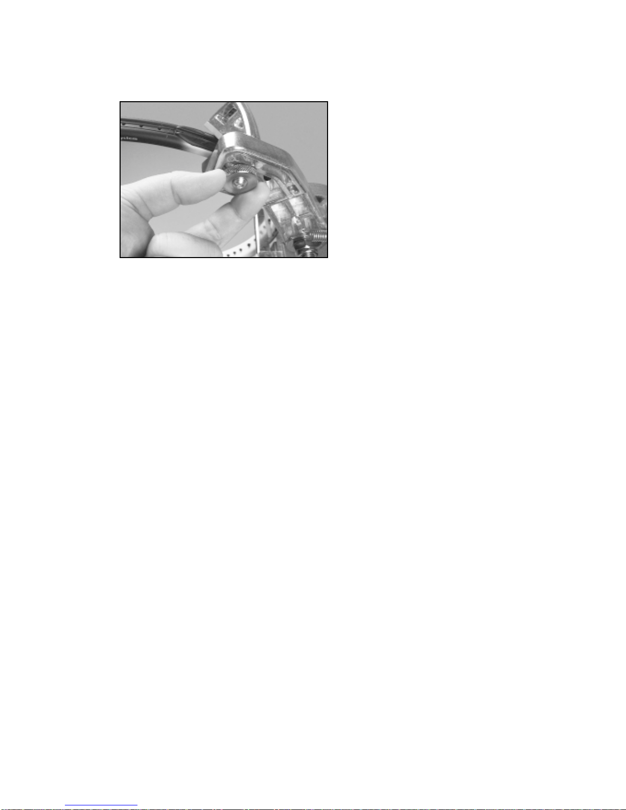
Clamp Head Operation
Clamps are of a dual action design where
as the clamp head and clamp base operate indepen-
dently of one another.
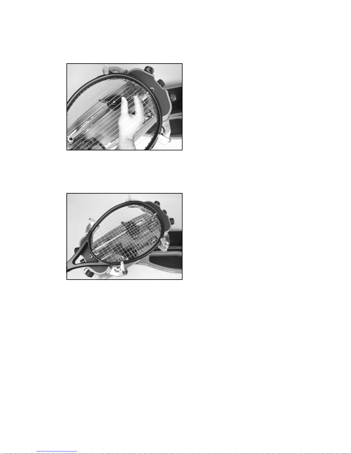
Toclampastring,lifttheclampheadandplacethestring
between the jaws and depress the clamp head lever to
secure the string. The clamping pressure applied to the
string should be adjusted to provide sufficient pressure
tosecurethestringwhensubjectedtothedesiredpulling
tension. The diamond coated gripper plates provide for
increased friction between the clamps and the string to
allow for reduced clamping pressure while securing and
holding the string under tension.
Note:Ifthestringslipsinthestringclampwhiletensioning,
adjust the gap between the clamp jaws per the instruc-
tions on page 13.
STRINGING THE FRAME
Travel Stop
Setting Tension
The Progression STII utilizes a rotary adjusting knob
along with a linear tension scale to indicate the tension
setting. The scale is divided into 3 lb increments and
each 1/3 turn of the tension knob changes tension by 1
lb. To set the desired tension, rotate the tension knob
and align the mark on the spring guide with the desired
tension setting on the scale. When the “0” mark on the
knobaligns withthe line onthe knobsupport the tension
willbethatindicatedonthescale.Toincreasetensionby
1 or 2 lbs turn the knob counterclockwise until the “1” or
“2” mark on the knob aligns with the line on the knob
support.Todecrease tension by1or 2 lbs,turntheknob
clockwiseuntil the“2”or“1” mark on the knob aligns with
the line on the knob support.
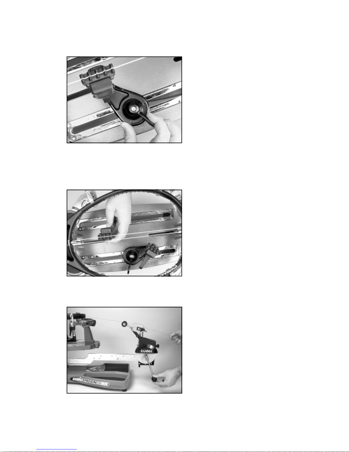
Tensioner Travel Stop
The tensioner bar is equipped with a tensioner travel
stop to limit travel of the tensioner along the bar and
prevent contact between the tensioner and the racquet
mounting system while stringing. The travel stop is
locatedaboutmidpointalongthetensionerbarbelowthe
gear track.
To disengage the stop, pull and hold the knob, rotate 90
degrees and release. To engage the stop, repeat the
above procedure until the travel stop pin protrudes
beyond the opposite surface of the tensioner bar.

8
STRINGING THE FRAME
Pulling Tension
Wrap theloosesection of stringoncearoundthe roller
guide and insert the string between the diamond dust
coatedstringgripperplates.Pullthestringperpendicu-
lar to the gripper plates while slowly rotating the
tensioner crank clockwise until the brake lever pops
out of the latching block. The string is now tensioned
and can be clamped in place with the remaining fixed
clamp.
Repeat the above steps until all main strings are
installed. Tie off ends of main strings as per racquet
manufacturers recommendations.
Clamping the First Main String
To begin stringing the main strings, thread the two ends
of the string through the two center holes at the appro-
priate end of the frame and continue through the oppo-
site center holes. Thread one end of the string through
the adjacent grommet hole and pull excess by hand.
Secure one of the strings using a string clamp.
Clamp Base Operation
Rotate the Base Locking Lever clockwise to secure the
clamp base to the turntable.
Reverse the clamping procedure to unlock the string
clamp. The Locking Lever is spring loaded to assist the
unlocking of the clamp base.
The Locking Lever should be tightened enough to pre-
vent clamp base slippage on the turntable, when the
desired tension is placed on the string. To go from the
loose position to the clamped position and back, gener-
allyrequirestherotationpermittedbytheslotinthclamp
base. If the rotation is not sufficient to allow smooth
operation of, adjust the Clamp Base Locking Nut as
outlined on page 13.

9
STRINGING THE FRAME
Weaving the Cross Strings
Weavethecross strings over andunderthemainstrings
being careful to alternate the weave direction of each
consecutive cross string so as to be opposite of the
previously installed cross string.
Once the final cross string is tensioned and clamped, tie
off at the appropriate hole specified by the racquet
manufacturer.

10
PATHFINDER AWL
TheProgressionSTIIincludesthenewPathfinderstring-
ing awl which creates a pathway between and around
stringsto make insertingastringthroughtightgrommets
easier and quicker.
Insert the awl through the grommet hole in the same
manneras for traditional awls.ThePathfinder awlmust
be in the closed position before insertion.
Once the awl is inserted, pull the handle of the awl
outwardwhileholdingthetipsectioninplace,leavingthe
outer sheath in the grommet hole.
Insert the end of the string into the center of the sheath.
While holding pressure on the string, slowly pull the
sheath out of the grommet hole to leave the end of the
string exposed.

11
Tension Calibration Procedure
Step 1
Setthetensionto60 lbs. as indicatedby thelinear scale
androtaryknob.Placethestringononeendofatension
calibrator into a string clamp and secure. Place string
located on the other end of the calibrator into the string
tensioner and apply tension. If the brake lever releases
before 60 lbs. or after 60 lbs., the tension head should
be calibrated as follows.
Step 2
Loosen the 1.5 mm locking set screw (A) located on the
side of the latching block as shown. The set screw is
used to hold the adjustment screw in place.
Step 3
Iftheleverreleasesbefore 60 lbs., usingthe suppliedL-
shaped hex wrench, turn the adjustment screw (C)
located on the left side of the latch block counter-
clockwise to increase the engagement of the brake
release latch with the brake lever. Repeat step 1 and
adjust until the correct tension is indicated on the
calibrator.
If the tension indicated in step 1 is greater than 60 lbs.,
turn the adjustment screw clockwise to reduce the
engagement of the brake release latch with the brake
lever. Repeat step 1 and adjust until the correct tension
is indicated on the calibrator.
MAINTENANCE and ADJUSTMENTS
B
C
A

12
Adjusting the Tensioner Brake
Step 1
Afterstringingmanyracquets,thebrakeofthetensioner
may need to be adjusted.
With the brake lever engaged, loosen the lock bolt
located on the back side of the tensioner frame with the
4mm hex wrench.
Note: The lock bolt should only be loosened enough to
beturnedbyhandandmustnotberemovedcompletely.
Adjusting the Tensioner Brake
Step 2
Withthelockboltloosenedandthebrakeleverengaged
inthelatch,insertthe6mmhexwrenchthroughthehole
in the tensioner cover and into the (B) brake lever
adjusting bolt.
B - Brake Lever Adjustment Bolt
Adjusting the Tensioner Brake
Step 3
To tighten the braking mechanism, turn the brake lever
adjusting bolt counter clockwise by about 1/8 turn.
Retighten the lock bolt on the back side of the tensioner
frame and check for brake tightness. The tensioner
should move freely along the track with the brake lever
engaged and should hold tension with the brake lever
released. If more adjustment is needed, repeat steps
above until properly adjusted.
Note: Cover Removed For Clarity
MAINTENANCE and ADJUSTMENTS
A - Lock Bolt
A
B

13
MAINTENANCE and ADJUSTMENTS
Adjusting the Clamp Jaws
The Clamps will need minor adjustments
according to what string type, construction, and gauge
you are using.
To adjust the gap (clamping pressure) between the
clamp jaws, insert the string through the racquet as if
you were beginning the main strings. Clamp the strings
andpulltension.Ifthestringslipsthroughthejawsofthe
clamp, tighten the clamp by compressing the clamp
jaws together by hand while turning the Adjustment
Knob, in the clockwise direction. If the clamp leaves
impressions or damages the string, it may be exces-
sively tight and should be adjusted by turning the hex
screw counter clockwise to open the gap between the
jaws. The clamp jaws should be cleaned periodically to
be free from dirt, oil, and any string coating for them to
grip properly.
Note: The string clamps supplied with your stringing machine can accomodate tight string patterns such as
badminton. Depending on the string pattern, the clamp may spread the strings slightly which will not compromise the
quality of the string job.
Clamp Base Locking Nut Adjustment
In the event the Locking Lever rotation is insufficient to
ensure smooth operation of the clamp base, very minor
adjustments to the Clamp Base Locking Nut can be
madewith the supplied17mmwrench. Tighten orloosen
the locking nut in very small increments to provide more
clamping pressure or running clearance as needed.
Turntable Bushing Adjustment
The Progression STII is adjusted at the factory for
optimum performance. After time and use, the turn-
table bushings may need minor adjustment. An adjust-
ment is indicated when noticeable turntable looseness
or wobble occurs while stringing.
To adjust the fit between the turntable pin and the
bushings, tighten the set screws located on the back
sideofthe tensioner barpostusinga 3mm hexwrench.
Tighten until the turntable rotates smoothly without
excessive free play.
Adjustment
Knob

14
TROUBLESHOOTING TIPS
With time and use, the clamping surfaces of your machine may become oily or dirty and result in string or clamp
slippage while stringing. Periodic cleaning of the following parts is recommended.
String Clamps
Cleanthe inside grippingsurfacesof the stringclampjaws by insertingacloth or pipecleanersoaked with isopropyl
alcohol between the jaws and rub back and forth. If the build-up is excessive, dismantle the string clamp jaws to
expose the gripping surfaces by removing the adjustment knob. Using a small nylon brush, (such as a toothbrush),
scrub the inside surfaces until all debris is removed. Clean the jaws with isopropyl alcohol and re-assemble.
String Clamp Base
Clean the base of the clamps and the top of the turntable with isopropyl alcohol.
String Gripper
Clean inner gripping surfaces with isopropyl acohol soaked cloth or pipe cleaner.
CARE and CLEANING
For additional assistance, contact Customer Service
PROBLEM SOLUTION
String clamp base slips on turntable. - Adjust Clamp Base Locking Nut.
- Clean Turntable Clamp Glide Rails
String slips in gripper. - Clean gripper jaws.
- Adjust Gripper Jaw Stop Screw
Tensioner slips on Tensioner Bar
after brake lever is released. - Adjust tensioner brake lever
- Clean tensioner brake disc
String slips in clamps - Adjust gap between jaws
- Clean clamp jaws
String tension too tight or too loose - Check tension using a tension
calibrator and adjust machine calibra
tion if necessary

15
EXPLODED PARTS VIEW

16
PARTS LIST
PART #
4A
5
6
7
8A
9
13
14
15A
21
22
23
24
104
105
106
107
122
140
141
142
143
144
DESCRIPTION
TURNTABLE BUSHING
RUBBER FEET
CAP SCREW
FOOT NUT
BUSHING SET SCREW
WASHER - M8
POST LOCK LEVER
WASHER - M10
2021 SUPPORT POST
FRAME SUPPORT SLIDE
BADMINTON ADAPTER
TENNIS ADAPTER
SUPPORT SLIDE KNOB
TENSIONER ASSEMBLY
RETAINER SCREW
TABLE BRAKE KNOB
TENSIONER BAR
SHOULDER PADS (RED)
MTNG. STAND TOP PLATE
MTNG. STAND PAD
SUPPORT ARM - LEFT
SUPPORT ARM - RIGHT
SUPPORT LOCK KNOB
PART #
145
146A
147
148
172
174
180
189
190
191
192
70
72
73
98
108
109
167
170
196
DESCRIPTION
ARM RETURN SPRING
ARM ADJUSTMENT KNOB
ARM ADJUSTMENT SCREW
SHOULDER V-CLAMP
2020-25 TURNTABLE
QA CLAMP w/GLIDE BAR
COMP. FIXED CLAMP (THIN)
PII LOWER TRAY PAD
PII UPPER TRAY PAD
PII ST ALUMINUM BASE
PII ST PS BASE COVER
HEX WRENCH - 5MM
PATHFINDER AWL
STRINGERS AWL
BOX WRENCH - 10MM
UTILITY KNIFE
NEEDLE NOSE PLIERS
10 PC. HEX WRENCH SET
M10 SUPP - POST SCREWS
BOX WRENCH - 17MM
TOOLS AND ACCESSORIES
This manual suits for next models
1
Table of contents
Other Gamma+ Accessories manuals