Gamma+ X-Stringer XLT User manual

OWNER’S MANUAL
Issue 1 - September 2018
XLT
ELECTRONIC
STRINGING MACHINE

2
XLT
OWNER’S MANUAL
LIMITED WARRANTY
GAMMA Sports (GAMMA) warrants to the original purchaser that the XLT stringing machine (“EQUIPMENT”) purchased is
free from defects in materials and workmanship for a period of fi ve (5) years from the date of original purchase for mechani-
cal parts and for a period of one (1) year from the date of purchase for all electrical parts and string clamps. Should any
defects develop under normal use within the specifi ed time periods, GAMMA will at its option, repair or replace the defective
EQUIPMENT provided it is returned to GAMMA prepaid at the purchaser’s expense. This warranty does not apply to any
damage or defect caused by negligence, abuse, misuse, unauthorized alteration, shipping, handling, or part wear and tear
as a result of normal use.
Routine maintenance, adjustment, and cleaning required to ensure proper operation are the responsibility of the purchaser and
are not covered under the terms of this warranty. These include, but are not limited to: String Clamp adjustment, as described
on page 16, Quick Action Clamp Base adjustment, as described on page 16 and the cleaning procedures listed on page 16.
GAMMA’s obligation under this warranty is limited to repair or replacement of defective EQUIPMENT, and no one is authorized
to promise any other liability. GAMMA shall in no event be liable for any incidental or consequential damages.
To return defective EQUIPMENT, a return authorization (RA#) must be obtained from a GAMMA customer service representa-
tive. The RA# must be marked on the outside of the shipping carton being returned. All returns must be shipped prepaid by
the customer to GAMMA. Please retain the original shipping carton and packing materials for any future shipments. GAMMA
will not be responsible for machines which are not sent in the original undamaged packaging.
A GAMMA Care Service Plan is also available through GAMMA customer service, call 800.333.0337 for details.
TABLE OF CONTENTS
WARRANTY ................................................................................................ PAGE 2
KEY FEATURES ......................................................................................... PAGE 3
ASSEMBLY INSTRUCTIONS ..................................................................... PAGE 4
POWER CONNECTION & CONTROLS ..................................................... PAGE 6
MOUNTING THE FRAME ........................................................................... PAGE 9
STRINGING THE FRAME ......................................................................... PAGE 10
ADDITIONAL FEATURES ......................................................................... PAGE 13
PATHFINDER AWL .................................................................................... PAGE 14
MAINTENANCE & ADJUSTMENTS ......................................................... PAGE 15
TROUBLESHOOTING TIPS ..................................................................... PAGE 17
PARTS LIST ............................................................................................. PAGE 18
PARTS DRAWING..................................................................................... PAGE 19

3
MACHINE FEATURES
Electric Constant Pull Tensioner with 11.0 to 90.0 lbs Tension
Range
Digital Tension Setting with LED Display
Parallel Jaw Linear Gripper with Textured Gripping Surfaces
Professional Six Point “Quick Mount” Racquet Mounting
System- Accommodates All Racquets
Professional “Quick Action” Dual Action, Rotating String Clamp
Bases
5 Tooth, Universal String Clamps with Textured Gripping
Surfaces
High Strength Extruded Aluminum Base with Durable Anodized
Finish
Large (Removable) Padded Tool Tray
FEATURES

4
ASSEMBLY INSTRUCTIONS
Leg Bracket with Foot Pads
There are four rubber foot pads supplied
with the machine. Two have exposed
threads and two have a spacer sleeve
over the threads. Install the two rubber
foot pads with the exposed threads into
the outer holes on both ends of the leg
bracket.
Mounting the Leg Bracket
Insert two hex head cap screws to the
holes next to the rubber foot pad.
Mounting the Leg Bracket
Attached the leg bracket on the left side
of the base by aligning the holes in the
leg bracket with the threaded holes in
the rails located on the underside of the
machine base as shown. Tighten the hex
head bolts.
NOTE: If desirted, the Leg Bracket may
also be installed on the right side of
the base. If this position is desireable,
the Tool Tray must be installed prior
to installing the Leg Bracket.

5
ASSEMBLY INSTRUCTIONS
Rubber Foot Pad Installation
Insert the two rubber foot pads with the spacer sleeve into the into the threaded holes of the
rails located on the underside of the baser on the right side as shown.
NOTE: If desirted, the Rubber Foot Pads may also be installed on the left side of the
machine base.
Installing the Tool Tray
Hold the tool tray on an angle and align the tabs
on the tool tray with the slots in the machine
base. Rotate the tool tray down and apply
pressure until the tool tray “snaps” into place.
Secure the tool tray with three bolts in the
bottom of the machine base from underneath.
Reverse the steps above to remove the tool
tray for ease of travel.
NOTE: If the Leg Bracket is installed on
the right side of the base, the Tool Tray
must be installed prior to installing the
Leg Bracket.

6
POWER CONNECTION & CONTROLS
Back Panel Features
A - Power On/Off Switch
B - A/C Power Cord Socket
C - Foot Pedal Switch Receptacle
Instructions for Power Connection and Controls
CAUTION ! Before connecting to the power supply, check the voltage source that the
machine is being connected to. The acceptable range of input voltages for this ma-
chine is between 100 V and 240 V @ 50 to 60 Hz. If you have any questions regarding
the input voltage supply for your area, please ask your electric utility company.
To install the power cord, insert the female end of the power cord into the AC Adapter and
then insert the female end of the cord from the AC Adapter into the A/C Power Cord Socket
“B” located on the back panel of the tensioner. Plug the male end of the power cord into a
grounded power outlet. When using extension cords, use grounded heavy duty extension
cords rated for 15 AMP service.
To connect the foot pedal switch, insert the male pin at the end of the foot pedal switch cord
into the Foot Pedal Switch Receptacle “C” located on the back panel of the tensioner.
Switch on the machine by pressing the Lighted On-Off Power Switch on the back panel. At
start-up, the LED will display a countdown from “9.0” to “0.0” while the machine performs a
self diagnostics check at start-up.
A C
B
A
C
B
D
Front Panel Features
A - String Gripper
B - Tension Lever
C - Control Panel
D - LED Display

7
WARNING! FOR INDOOR USE ONLY.
NEVER OPEN UNIT WITH POWER CONNECTED.
CHILDREN SHOULD NEVER BE PERMITTED TO OPERATE THIS
MACHINE WITHOUT ADULT SUPERVISION.
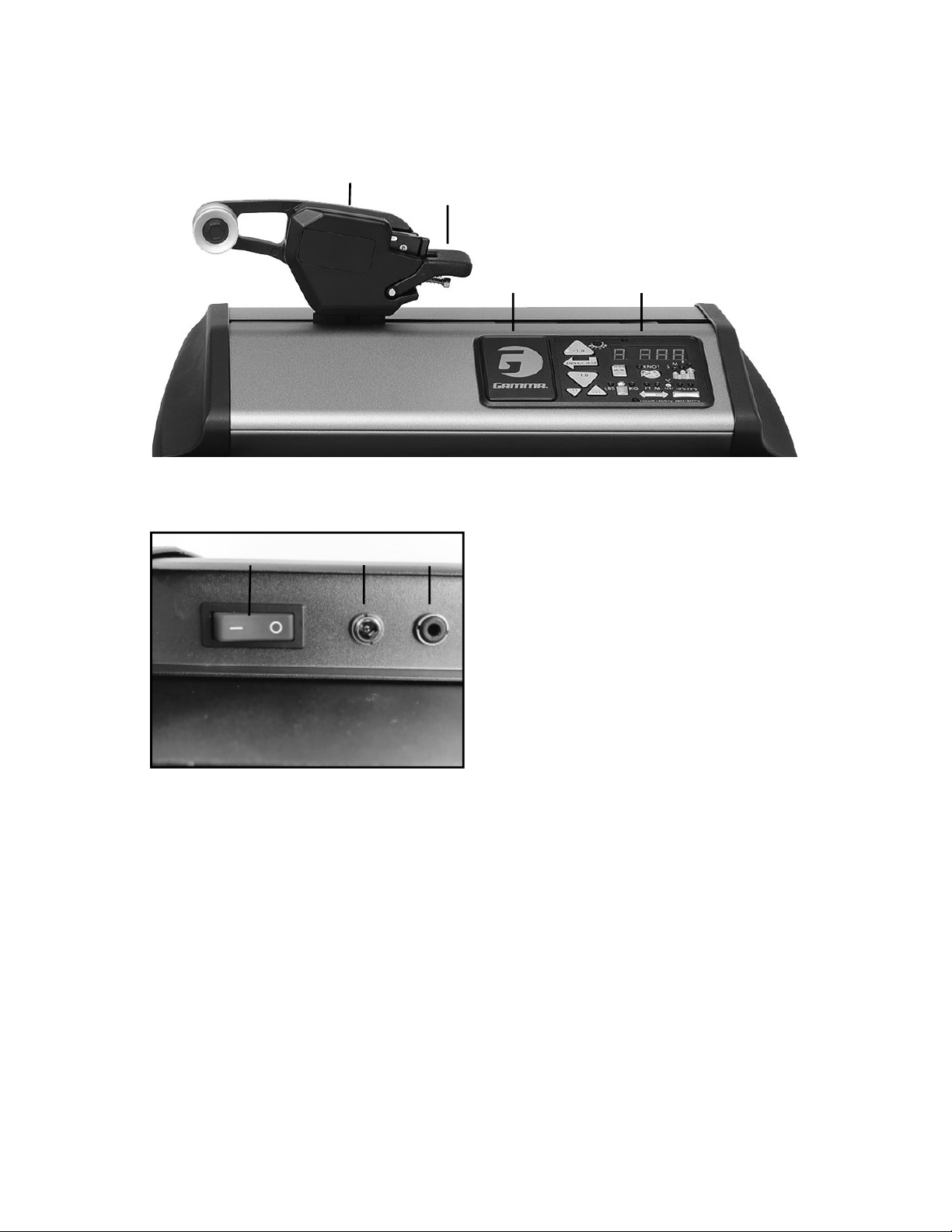
CONTROL PANEL FUNCTIONS
AND FEATURES
Single Digit (1-9)
Memory LED Display
Three Digit (XX.X) Tension
Setting LED Display
Tension Index Buttons - Changes
tension setting in +/- 1.0 or +/- 0.1 Lb or
Kg increments. Holding the button down
will scroll the tension setting values up
or down. Tension settings entered with
the tension index buttons are placed into
temporary memory setting “0”.
Clear Button - Clears display to enter
a new tension or to reset String Length
Meter measurement.
Test Button & Racquet Strung -
Press once for approximate number of
racquets strung. Press again to return.
Press and hold for 5 seconds and the
machine does an internal diagnostic
check, such as the one performed at
start-up.
Lbs/Kgs Button - Changes tension
display from Lbs to Kgs. Each press
of the button toggles back and forth
between Lbs and Kgs.
Pre-Stretch Function - Pulls string 10%
or 20% over the tension setting (up to 90
lbs / 40.8 kgs), releases the string, and
repulls to the tension setting. Each press
of the button toggles between 10%, 20%
or no pre-stretch.
Memory Button - Indexes from 9 preset
tension settings that can be stored in
memory. Settings are retained even if
machine is turned off . Each press of
the button indexes to the next memory
setting. Memory settings 1-9 must be
entered using the keypad followed by
pressing the “ENT” button.
Enter Button - Saves displayed tension
for Memory setting - when tension is en-
tered using the keypad display fl ashes
until this button is pressed to save the
setting. Also Clears display for String
Length Meter measurements.
Knot Function - Increases pulling ten-
sion by 10% over the setting value (max
90 lbs / 40.8 kgs) for one pull. During the
pull the LED stays lit to indicate the Knot
function is enabled.
Speed Button - Changes pulling speed
of winder from Fast (default) to Medium
to Slow. Slow speed is recommended
for low stretch strings, such as Kevlar.
Each press of the button toggles be-
tween Fast, Medium and Slow speeds.
String Length Meter Button - feature is
currently not available.

8
STRING CLAMP INSTALLATION
String Clamp Installation
The post of the string clamp and tube of the
string clamp base are treated with grease to
provide protection against corrosion during
shipping. Remove any excessive grease with
a clean cloth prior to use. The post and tube
may also be cleaned with isopropyl alcohol.
After this type of through cleaning, the post
and tube should be treated with a light coating
of machine oil to protect the surfaces against
corrosion and to ensure smooth operation.

9
Adjusting the Frame Support Posts
Loosen the lock bolts of the frame support
posts and space them apart with the frame
support slides separated by the approximate
length of the racquet head. Although it is not
required, it is good practice to center the sup-
port posts on the turntable. Lock one of the
posts in position by tightening the lock bolt
and position the other post until the frame
support slide is positioned near the inside
surface of the racquet frame. Securely tighten
the lock bolt of the second support post.
Caution: To avoid racquet damage, the center posts should not contact the racquet prior to
locking down the support posts.
Frame Shoulder Support Adjustment
Simultaneously rotate the shoulder support
adjustment knobs clockwise until both shoulder
supports gently and squarely contact the frame.
Rotate the shoulder supports as needed so the
pads make fl ush contact with the racquet frame.
Repeat this procedure for the remaining sup-
port posts.
The supports should be tightened to the point
where the racquet frame will not move in the
mounting system when the handle is grasped
and attempts are made to move it. Should any supports lose contact with the frame while
stringing, they should be re-tightened.
Caution: Do not overtighten any of the supports as racquet damage may occur.
Tightening the Frame Supports
Tighten the Frame Support Slides by turn-
ing the adjustment knob clockwise until
snug against the racquet frame and slight
resistance is felt.
Caution: Overtightening the Center Supports
will stretch the head of the racquet and could
cause racquet damage.
MOUNTING THE FRAME

10
STRINGING THE FRAME
String Clamp Operation
The string clamps are a dual action design
where the string clamp and clamp base oper-
ate independently of one another.
To clamp a string, lift the string clamp to place
the string between the jaws and depress the
string clamp lever to secure the string. The
clamping pressure applied to the string should
be adjusted to provide suffi cient pressure
to secure the string when subjected to the
desired pulling tension. The textured gripping
surfaces on the teeth of the string clamps
provide for increased friction between the
clamps and the string to allow for reduced
clamping pressure while securing and holding
the string under tension.
Note that excessive pressure can damage
both the strings and String Clamp.
Clamp Base Operation
To lock the string clamp base to the turntable,
rotate the clamp base locking lever clockwise.
To release the string clamp base from the
turntable, rotate the clamp base locking lever
counter-clockwise.
The Locking Lever should be tightened enough
to prevent clamp base slippage on the turntable,
when the desired tension is placed on the string.
Getting Started
To begin stringing the main strings, thread
the two ends of the string through the two
center holes at the appropriate end of the
frame and continue through the opposite
center holes. Thread one end of the string
through the adjacent grommet hole and pull
excess by hand.
Secure one of the strings using a string clamp.

11
STRINGING THE FRAME
Applying Tension
Before applying tension, gently pull the string until all slack is removed.
To apply tension, wrap the string clockwise around the String Guide and position the string
between the two gripper jaws.
CAUTION: NEVER TENSION A STRING WITH YOUR FINGERS BETWEEN THE
STRING AND THE STRING GUIDE AS SERIOUS INJURY COULD RESULT IF
YOUR FINGER IS CAUGHT BETWEEN THE STRING AND STRING GUIDE WHEN
TENSION IS APPLIED TO THE STRING.
IN CASE OF EMERGENCY, PRESSING ANY BUTTON ON THE CONTROL PANEL
WILL RELEASE THE TENSION ON THE STRING.
To tension a string, push the tension switch
or the foot pedal. The string gripper will rotate
and slowly apply tension to the string. When
the set tension has been attained, the grip-
per will stop and the display will fl ash. As the
tensioned string stretches, the gripper may
apply tension intermittently, maintaining the
set tension.
To release the string after clamping, push the
tension switch or foot pedal. If the string grip-
per does not release the string, depress and
hold the return button to release the string.

12
STRINGING THE FRAME
Weaving the Cross Strings
Weave the cross strings over and under the
main strings being careful to alternate the
weave direction of each consecutive cross
string so as to be opposite of the previously
installed cross string.
Completing the String Job
Once the fi nal cross string is tensioned and
clamped, tie off at the appropriate hole speci-
fi ed by the racquet manufacturer. Remove the
frame from the mounting system by loosening
the shoulder supports and frame supports.
Clamping the First Main String
Secure the tensioned main string using the
remaining fi xed clamp. Repeat the procedure
for all of the remaining main strings and
tie off following the racquet manufacturers
recommendations.
Follow the manufacturer’s recommended
stringing pattern for one or two piece string-
ing. This will determine the starting point for
the cross strings. If applicable, tie the fi rst
cross string using an appropriate starting
knot.

13
ADDITIONAL FEATURES
Turntable Brake
The turntable may be locked in any position.
To engage the turntable brake, rotate the brake
lever clockwise.
To release the brake, rotate the brake lever
counter clockwise.
Badminton Shoulder Support
Protection Pad Installation
Slide the badminton shoulder support cover
over the shoulder supports. There is no need
to remove the tennis shoulder supports.
Note: An optional badminton frame support
for the head of the racquet is available.
Turntable Brake Lever - Released Position
Turntable Brake Lever - Engaged Position

14
PATHFINDER AWL
Once the awl is inserted, pull the handle of
the awl outward while holding the tip section
in place. This leaves the outer sheath in the
grommet hole. Insert the end of the string
into the outer sheath.
While holding the string, slowly pull the sheath
out of the grommet hole to leave the free end
of the string exposed.
The machine includes the pathfi nder string-
ing awl which creates a pathway between
or around strings to make inserting a string
through blocked grommets easier and
quicker.
Insert the awl through the grommet hole in
the same manner as for traditional awls. The
Pathfi nder awl must be in the closed position
before insertion.

15
MAINTENANCE & ADJUSTMENTS
Tension Calibration Procedure
Each stringing machine has been checked and calibrated at the factory using accurate load
sensing devices to ensure that the machine pulls at the correct tension. However, if you suspect
that your machine may not be pulling at the correct tension you can check the pulling tension
with a calibrator and make adjustments if needed.
Most tension calibrators (such as a Gamma Tension Calibrator) function by clamping off the
string attached to one the end of the calibrator and applying tension to the string located on
the opposite end of the calibrator. The tension measured by the calibrator will then display
the tension being applied to the calibrator by the machine. If the calibrator and tensioner do
not match then you can adjust the tensioner as follows:
(1) Turn the machine off and restart the machine while holding down the Test button until
the count down is complete. 22 lbs should appear on the display. (2) Apply tension to the
calibrator. (3) If the tension reading on the calibrator does not match the tension displayed on
the machine, use the tension indexing buttons to match the display to the calibrator reading
and press the Enter/Clear button (4) Release the tension applied to the calibrator and 44 lbs
should appear on the display. (5) Repeat steps #2-#4 for 44, 66 & 88lbs. (6) After completing
the adjustment at 88lbs the display will show 00 lbs. (7) Restart the machine without holding
any buttons and the calibration adjustment will be complete.
Switching the Buzzer Off and On
The stringing machine is equipped with a buzzer that sounds when any key or button is
pressed or when there is a problem with some function of the machine. The buzzer can be
disabled if desired for normal keypad entries.
To disable the buzzer, turn the machine on and while the display is counting down from 9 to
0, press and hold the Enter/Clear button for at least 5 seconds. The buzzer will be disabled
and will remain disabled. It can be enabled again by following the same steps listed above.
Note: Even when disabled, the buzzer will sound if the tensioner has a problem and the
machine requires attention. This is meant to alert the user of a problem, and can not be
disabled.

16
Adjusting the String Clamp Jaw
Spacing
The string clamps will need minor adjust-
ments according to what string type, con-
struction, and gauge you are using.
To adjust the gap (clamping pressure)
between the clamp jaws, insert the string
through the racquet as if you were beginning
the main strings. Clamp the strings and pull
tension. If the string slips through the jaws of
the clamp, tighten the clamp by squeezing the
clamp jaws together by hand while turning the
Adjustment Knob, in the clockwise direction.
If the clamp leaves impressions or damages
the string, it may be excessively tight and should be adjusted by turning the Adjustment Knob
counter clockwise to open the gap between the jaws.
NOTE: Due to the bearings used in the Clamp Lever the action of the Clamp Lever is
very light making it easy to apply excessive clamping pressure. Clamps that are set
too tight can damage the string as well as the string clamp jaws.
The clamp jaws should be cleaned periodically to be free from dirt, oil, and any string coating
residue to grip properly. Knife sharpening stones are excellent for removing build-up on the
diamond coated surfaces and are available.
Adjustment
Knob
MAINTENANCE & ADJUSTMENTS
Clamp Base Locking Nut Adjustment
In the event the Locking Lever rotation is insuf-
fi cient to ensure smooth operation of the clamp
base, very minor adjustments to the Clamp Base
Locking Nut can be made with the supplied
17mm socket. Tighten or loosen the locking nut
in very small increments to provide more clamp-
ing pressure or running clearance as needed.
Quick Action Clamp Base Removal
Quick Action clamp bases can be removed
from the turntable for maintenance or cleaning
by removing clamp stop located at the end of
the slot in the turntable. To remove the clamp
stop, remove the two screws holding the clamp
stop in place from the underside of the turn-
table. Lift the clamp stop out of the slot, slide
the clamp base to the end of the slot and lift it
out. Replace the clamp base and clamp stop
in reverse order.

17
TROUBLESHOOTING TIPS
PROBLEM SOLUTION
String slips in clamps - Adjust gap between clamp jaws
- Clean clamp jaws
String slips in gripper - Clean gripper jaws
- Make sure string is wrapped over top gripper
prior to inserting between gripper jaws
String clamp base slips on turntable - Clean bottom of clamp & top of turntable with
alcohol
- Adjust clamp base locking nut
Electrical system does not function - Check power source
- Check power cord connections
String tension too tight or too loose - Check tension using a tension calibrator,
adjust machine calibration if necessary
CARE & CLEANING
With time and use, the clamping surfaces of your machine may become oily or dirty and result
in string or clamp slippage while stringing. Periodic cleaning of the String Clamps, String Clamp
Base and String Gripper is recommended. Knife sharpening stones work well for cleaning the
diamond coated string clamping surfaces. Cleaning with a solvent such as isopropyl alcohol
and a mild abrasive tool such as a toothbrush also works well to remove oily or greasy build up.

18
MMP11-16 FOOT PEDAL SWITCH*
MBFC BADM FLOATING CLAMP*
MBFS-14 BADM HEAD FRAME SUPP*
MGSMC MACHINE COVER*
MPG STARTING CLAMP*
MXLFS FLOOR STAND*
MTC TENSION CALIBRATOR*
SGSM STRINGER’S MAT*
MBMSS11 BADM MNTG SYS UPGRADE*
6A CAP SCREW- M8x30
9 WASHER- M8
194 TT CLUTCH PAD
203 TT BOLTS*
270 SUPP POST MOUNT PLATE
283 TT END CAP - CENTER
285 TT END CAP- RIGHT
286 TT END CAP- LEFT
289 TT HANDLES
301 RUBBER FOOT
320 BRAKE RING
327 TT PIN
360 TURNTABLE TT7
363 A220 MNTG STAND
364 A220 MNTG ARM (R)
365 A220 MNTG ARM (L)
366 A220 TOP PLATE
367 A220 TOP PLATE/ARM PADS
368 A220 ADJ KNOB & SCREW
369 A220 FRAME SLIDE KNOB
370 ADJ KNOB RUBBER GRIP
371 A220 SHLDR V-MNT (BLK)
372 A220 FRAME SUPPORT
375 DC LINEAR GRIPPER BLK
406 TT CLUTCH BOLT
407 TT CLUTCH SPRING
430 XLT BASE
431 XLT RUBBER FOOT SLEEVE
432 XLT BASE LEG
433 XLT TOOL TRAY
434 XLT TOOL TRAY PAD
435 XLT TENSIONER
436 XLT TENSIONER UPPER CAP (R)
437 XLT TENSIONER UPPER CAP (L)
438 XLT TENSIONER LOWER CAP (R)
439 XLT TENSIONER LOWER CAP (L)
440 XLT TT BRAKE BOX
71 6MM T-HANDLE HEX WRENCH*
109 NEEDLE NOSE PLIERS*
110 BENT NOSE PLIERS*
167 HEX WRENCH SET*
171 DIAGONAL CUTTERS*
196 17MM SOCKET*
E16 A/C POWER CORD*
E23 AC ADAPTER*
MA STRINGER’S AWL*
MFSPP13 FRAME SUPP PAD SET BLK
6 FRAME PADS
2 BAD SLIDE ON “H” PADS
MMSPP13 V-MNT SHLDER SUPP PADS
MBMSP11 BADM V-MNT COVER
MPSA PATHFINDER AWL*
OPTIONAL TOOLS & ACCESS
PART # DESCRIPTION
TOOLS & ACCESSORIES
E76 KEY PAD / ELECTRONICS
MFASC10 TENNIS STRING CLAMP
MQAC12 QA CLAMP BASE TALL TT7/TT8
PART # DESCRIPTION
PARTS LIST
* INDICATES ITEMS THAT ARE NOT SHOWN

19
PARTS DRAWING
364
433
440
320
431
289
327
435
283
285
286
270
96A
MFASC10
MQAC12
372
367
MMSPP13
365
E76
366
363
301
194 430
437
369
360
MFSPP13
MBMSP11
371
368
370
406 301
432
439
407
434
375
436
438
9
6A

GAMMA SPORTS
200 Waterfront Drive
Pittsburgh, Pennsylvania 15222
Phone: 800.333.0337 Fax: 412.323.0317
Visit our website at www.gammasports.com
Copyright 2018 GAMMA Sports - All Rights Reserved
MMAN69
(MGXLT-10)
Table of contents
Other Gamma+ Accessories manuals
Popular Accessories manuals by other brands

Siko
Siko MS500 quick start guide

Zephyr
Zephyr PRB24C01AS-OD Use, care and installation guide

Minebea Intec
Minebea Intec PR 6207 installation manual

Fritel
Fritel EK 3180 instruction manual

Sanus Systems
Sanus Systems Screen Care Kit ELM101 product manual

Setra Systems
Setra Systems SRH operating instructions