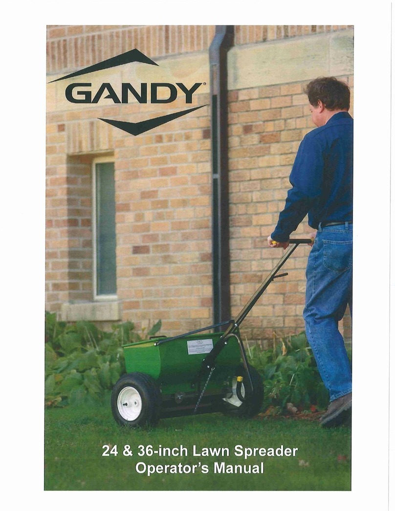
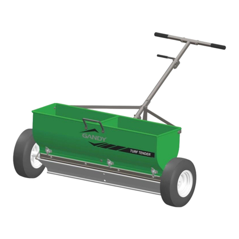
Gandy 10T Series User manual

10T Series
January 2018
Operator’s Manual
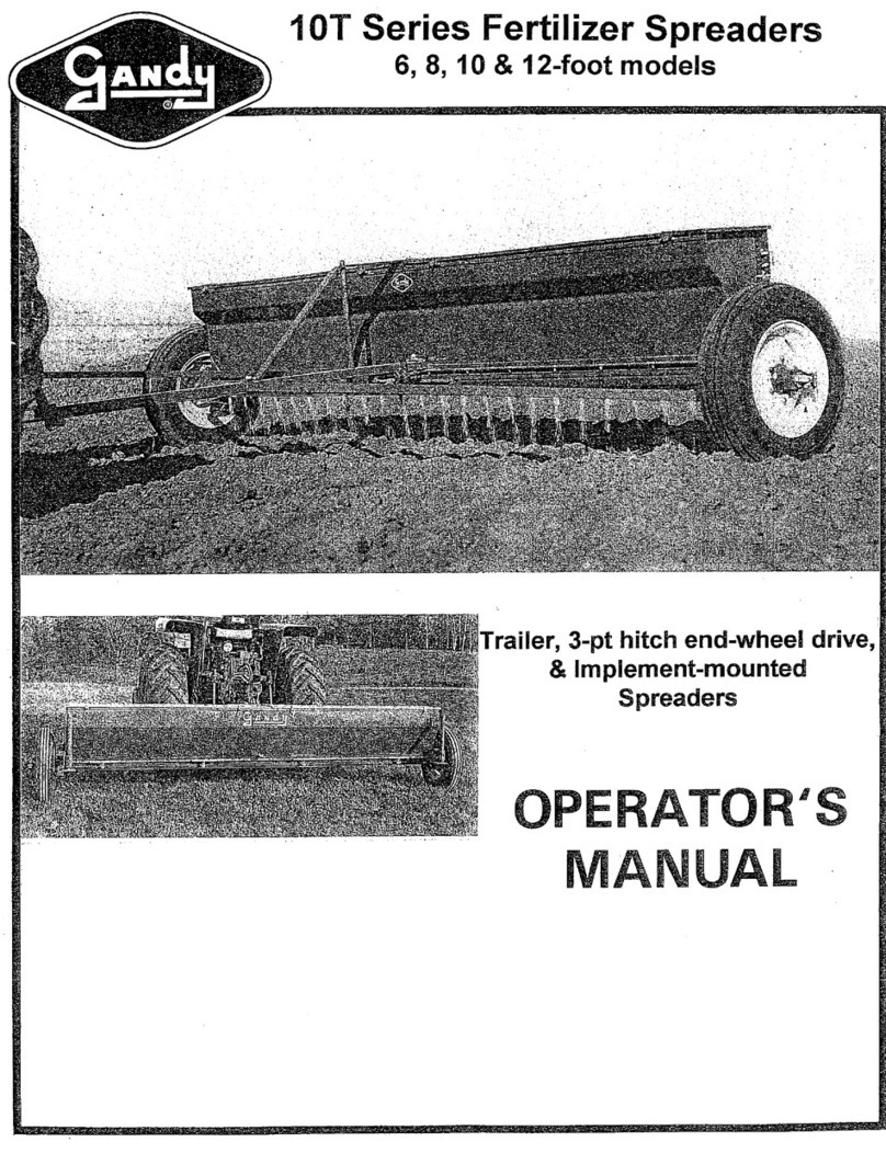
10T Series Drop Spreader
For 6, 8, 10 & 12-Ft Models
Pull-Type, End-Wheel Drive
& Implement Mounted
Pull-Type
End-Wheel Driven 3-Point Hitch
Implement Mount
Gandy Company
815 Rice Lake Street
Owatonna, MN 55060
Telephone: 507-451-5430 / 800-443-2476
Fax: 507-451-2857
Website: www.gandy.net
/


~ 1~
Maintenance of 10T Series Spreaders:
Lubrication of Spreader:
There are a total of 9 grease fittings on this spreader that need to be greased twice –a-day.
These 9 grease fittings are greased from the factory but double check that none were missed.
There is 1 on the optional hand shut-off, if used to be greased periodically as needed.
Left & Right Wheel Hubs & Wheel Hub Collars: (Three on Left End & Three on Right End)
The wheel hubs have a built-in grease reservoir and should be greased generously twice daily.
The front and rear collars need to be greased twice daily.
When properly lubricated grease should come out the parting line between the front and rear collars.
One Grease Fitting on Left & Right Wheel Hub
One Grease Fitting on Front & Rear Collar
Left & Right End & Center Bearing: (Three Total)
These three bearings need to be greased sparingly twice daily. Do not over grease as this will force excess
grease out into the spreader compartment and can cause interference with followability of material.
Grease Fitting Left & Right End Bearing
Grease Fitting Center Bearing
Knee Lever:
(only if using the manual shut-off lever)
Grease the knee lever mounted to the hitch by
the cam gauge periodically as needed.

~ 1~
Built in Ground Driven Wheel Hub Manual Operation:
For Pull-Type & 3-Pt End Wheel Driven Spreaders:
Out of Gear Position, Lever Up:
When traveling to a from field locations flip the clutch lever in the up Out of Gear position as shown in
illustration. When the lever is in the up position the rotor bars inside the spreader do not turn. This keeps the
spreader from grinding up the product that is in the rotor bar location
In Gear Position, Lever Down:
When applying material flip the clutch lever in the Down in gear position as shown in illustration. When the lever
is in the down position the rotor bars inside the spreader will turn agitating the material in the hopper to help it
evenly flow.

~ 1~
Cleaning of Spreader:
1)
Run spreader until it is empty or nearly so.
2)
Move the cam gauge to the highest position and empty hopper out.
Catch remaining material on a tarp or optional l calibration pans. Sweep out remaining material.
3)
To remove rotor bars pull out the stub drives on each end by pushing down on the clutch lever and pulling
stub drives out. (See Illustration)
The stub drives connect directly to the square rotor bar shaft. When the stub drives are removed this
releases the rotor bars for removal.
4)
Removing rotor bars.
With the stub drives removed grab one rotor bar and slide it the outside of the spreader and the lift the
center up and out of the hopper. Repeat this of the other side. Keep track of what side the rotor bars came
out from. With the rotor bars removed sweep out the remaining material and wipe clean.
5)
To clean any buildup of material between stainless slide strips and painted bottom the rear hangers will
need to removed. There are two nuts and nylon washers per rear hanger. Also there is on self-tapping
phillips head screw in the middle of each rear hanger. Remove all of these and tap the rear hanger the
direction of the slots to remove stainless slid strip assembly. With slides removed wipe both the bottom
and slides clean. Clean end and center bearings at this time. Clean stub drives and rotor bars at this time
also.
Before reassembling spreader place a very light coat of fine oil over bottom and slide and inside of hopper.
(WD40 or a spray on wax works well.)
6)
Reassemble the slide back to the bottom making sure the slide rails catch the lip of the rail (Cam-Gauge
side) on the bottom of the hopper. Install the rear hangers using the nylon washer and nuts. Gently tap the
rear hanger over till the center hole aligns with the hole of the self-tapping screw and start the screw in
place. Tighten the two nuts on each rear hanger. Tighten the self-tapping screw.
Check to see if the bottom moves smoothly but not to tight.
7)
Reinstalling the rotor bars.
There is a Left Rotor Bar painted Black and stamped “L” on square end.
There is a Right Rotor Bar painted Red and stamped “R” on the square end.
These need to be put back into their left and right sides. Stand behind the spreader with the hitch on the
opposite side of you to deuterium what is the left & right side. The rotor bars need to turn the claw down
(the direction you travel) for them to work correctly on wheel driven models. (See illustration)
With rotor bars reinstalled reinstall the stub drives back into hubs and connect to square end of rotor bars.
See page on greasing hopper & re-grease as needed.
Clutch Lever
Rotor Bar Removel
Rotor Bar Direction of Travel
`

~ 1~
Operation & Calibration:
1)
Observe the important service and safety decals located on the spreader.
N02-0014-010
N02-0014-020
N02-0057-000
2)
With spreader in the closed position fill hopper and close lids.
Check to see that spread-plates are set at desired angle. Spread plats can be adjusted by changing
how the sash chain is hooked to the spreader. Start with the spread plate at about 45 degrees. This
is a starting point. When using different materials the angle may need to be adjusted up or down to
create a sheet like flow for even coverage. Or the spread-plates can be removed to drop material in
slight streaked rows.
3)
Set the Cam-Gauge for the material you are using. The numbers on the Cam-Gauge are for
reference only and have nothing to do with your desired rate. The larger the number the more the
bottom opens or a higher applied rate. The smaller the number the less the bottom opens or a lower
applied rate.
Use the top edge of the stop as the gauge point for the line on the Cam-Gauge.
See rate chart for setting. If the material you are using is not listed pick a material that is close in
size and you will have to calibrate to get the desired rates you want.
4)
Before applying make sure to engage the wheel hubs by flipping the levers down and pulling ahead
a little to make sure the wheel hubs engage.
5)
Check calibration by one of the two methods described below.
Using the optional Calibration Pans or the know area method.
In conducting rate checks always maintain actual field operation speed.
To check your ground speed use the following chart comparing speed to distance traveled in one
minute.
1 mph
2 mph
3 mph
4 mph
5 mph
6 mph
7 mph
8 mph
9mph
10 mph
88 Ft.
176 Ft.
264 Ft.
352 Ft.
440 Ft.
528 Ft.
616 Ft.
704 Ft.
792 Ft.
880 Ft.
6)
After checking application rate apply material.
7)
Close slide to shut-off material flow and to prevent moisture from entering openings in hopper over
night or when spreader is not in use. Remember to disengage the wheel hubs when traveling to and
from locations.
Continued on Next Page….

~ 1~
Picture of a Calibration Pan Held in Place By Sash Chains
Using Calibration Pans:
Place calibrations pans on spread-plate using the sash chains to hold them in place.
Note: the 6-ft spreader only uses one pan all the others use two pans.
Fill the spreader about half full.
See chart below for size of spreader you have 6, 8, 10 or 12-Ft and mark out the distance to be
traveled. This distance equals 1/10 of an acre at the speed you with to travel.
Pick the speed you what to go and travel the distance listed in chart below collecting the material in the
calibration pans.
Begin moving ahead of marked off distance so you are traveling at desired speed.
Open bottom of spreader as the spreader passed the beginning of the marked off distance and then
close the bottom as the spreader passes the end of the marked off distance.
Weight material collected in pounds.
Multiply this weight by 10 to get the applied rate in pounds per acre.
Keep repeating this step until you get the rate you are looking for.
Keep tract of the setting and speed traveled for future use.
Your Spreader Width
Distance to Travel to Collect 1/10 of an Acre.
6-Ft Models
726 Feet
8-Ft Models
544 Feet, 6-inches
10-Ft Models
435 Feet, 8-inches
12-Ft Models
363 Feet
Know Area Method
Fill hoper. Treat a known area, such as an acre or two, and refill hopper to the same level, noting the
quantity used. Divide the amount required to refill by the area covered. The result will be your actual
application rate. In necessary, adjust Cam-Gauge setting to increase or decrease amount being
applied. Recheck. The following figures may help in your computations based on a filed length of 80
rods (1320-Ft), or one-quarter mile.
Your Spreader Width
Portion of Acre Covered in One Round
6-Ft
6-Ft or .38
8-Ft
8-Ft or .50
10-Ft
10-Ft or .63
12-Ft
12-Ft or .75

~ 1~
Powder Angle Packages for 10T Series Spreader
Standard with all Spreaders
Powder Angles are recommended for powdery fine light materials.
They are furnished with all “T” series spreaders.
Powder Angle
Package #.
C02-0250-020
(1/4” SAE Washer)
C03-0250-040
(1/4 x 1 Hex Bolt)
0506394-100
(Powder Angle 1”)
0506394-334
(Powder Angle 3-3/4”)
0566394-T (6-Ft)
Qty-18
Qty-18
Qty-2
Qty-16
0586394-T (8-Ft)
Qty-24
Qty-24
Qty-2
Qty-22
05106394-T (10-ft)
Qty-30
Qty-30
Qty-2
Qty-28
06127694-T (12-Ft)
Qty-36
Qty-36
Qty-2
Qty-34
0566394-T
Install alternately UP and Down.
Draw hex bolt snug without bowing 1/4 inch square rod as shown below.

~ 1~
Standard Equipment on All Spreaders.
Powder Paint Coated Steel Hopper & Removable Bottom and Rate Control Slide.
Cam-Gauge Controlled
Shur-Feed Rotor Bars with Removable Stub Drives for Rotor Bars.
Heavy Duty Grease Able Bearings
Adjustable Spread-Plate
Removable & Reversible Covers with Spill-Guards for Each Cover.
Powder Angles Included.
Hydraulic Shut-Off Cylinder. (Hydraulic Hoses Not included)
Operator’s Manual & Rate Charts & Assembly Instructions/Parts Lists.
Rear Hitch Extension for Pulling Non-Ground Engaging Equipment.
Optional Electric Shut-Off Ordered Separately.
Optional Calibration Pans Ordered Separately.
Specifications (All Models)
6-Ft
8-Ft
10-Ft
12-Ft
Spreader Capacity (Lbs)
600
800
1000
1200
Spreader Length (in)
73
97
121
145
Spreader With (in)
14.5
14.5
14.5
14.5
Spreader Depth (in)
22.5
22.5
22.5
22.5
Bottom Opening Size (in)
1-1/2
1-1/2
1-1/2
1-1/2
Spacing of Openings (in)
4
4
4
4
Total Openings
18
24
30
36
Specifications: For Pull-Type & End Wheel Driven 3-Point Hutch Models Only
Wheel Hubs - Grease Able Designed for Low Speeds. (NOT for high speed towing)
Ground Driven –Has three-position manual clutch, for in-gauged, dis-engaged and removal of stub
drives.
Hand Lever Manual Shut-Off Ships Only with Pull-Type Models.
Optional 15” Wheel Packages:
Standard Tire & Rim: 6.75 x 15 Rim, 6-ply Implement Rib Tire
Flotation Tire & Rim: 11L15 Rim, 6-ply Flotation Tire
Standard Tire Can Be Mounted Dished in or Dished Out for Different Widths.
Specifications
6-Ft
8-Ft
10-Ft
12-Ft
Ground Clearance to Bottom (in)
13
13
13
13
Ground Clearance to Spread-Plate
(in)
6
6
6
6
Center to Center Standard Tire (in)
Rims Dished In
86
110
134
158
Center to Center Standard Tire (in)
Rims Dished Out
91
115
139
163
Over all Width Standard Tires (in)
Rims Dished In
94
118
142
166
Over all Width Standard Tires (in)
Rims Dished Out
99
123
147
171
Flotation Tire Over All Width
110
134
158
182
Specifications: For TBM Implement Mounted & 3-Pth Models
Hydraulic Drive –Ordered Separate
OR
Electric Drive –Ordered Separate

~ 1~
LIMITED WARRANTY
The Gandy Company warrants all material and workmanship on equipment delivered to be free of
defects for a period of twelve months from date of original purchase. Products used on a
commercial, rental or leased basis are warranted for 90 days. Any part or parts thought to be
defective within these warranty periods are to be returned through your servicing dealer or
distributor to the Gandy Company's plant. Distributor must receive authorization from Gandy
Company to return items under warranty. An authorization number will be issued and must be
clearly visible on all packages returned to the factory. If found defective by Gandy Company,
replacement parts will be forwarded free of charge, prepaid. No service charge or expense on the
equipment will be allowed unless such expense has been previously authorized in writing by the
Gandy Company. Serial number and model of the unit involved is required by the Gandy Company
on all warranty claims. Gandy Company policy is to improve products whenever it is practical to do
so. It reserves the right to make changes or add improvements at any time without incurring any
obligation to make such changes on products sold previously. This warranty does not apply to
products altered by users after the point of manufacture.
This warranty against defects in material and workmanship is in lieu of all other warranties,
expressed or implied, and there are no other warranties of any kind whatsoever including, but not
limited to, any implied warranty of merchantability or fitness for any particular purpose. In no event
shall the company be liable for any incidental or consequential damages whether for breach of
warranty, for breach or repudiation of any other term or condition hereof, or for negligence, on the
basis of strict liability, or for any other reason.
This material contains information that is correct at the time of printing; however, Gandy Company
reserves the right to change specifications, models, equipment or prices without incurring
obligation. Images shown are for information purposes only, and may not necessarily represent the
configurable options.
Other manuals for 10T Series
1
This manual suits for next models
4
Table of contents
Other Gandy Spreader manuals