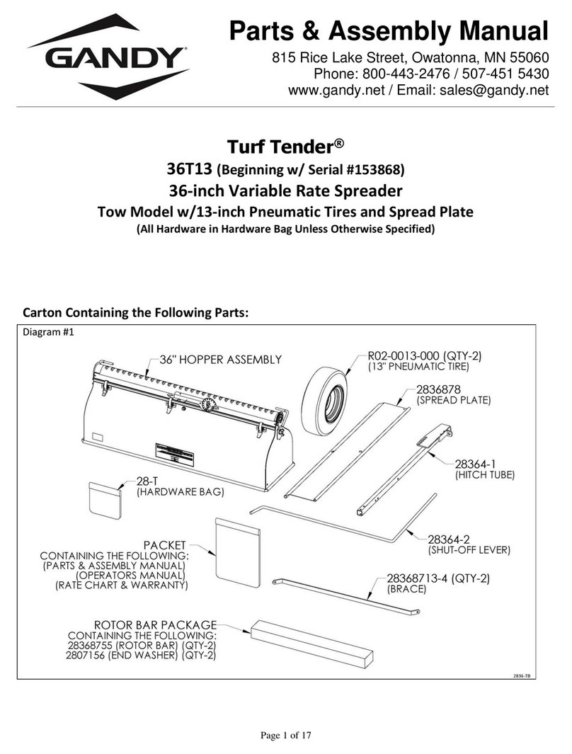
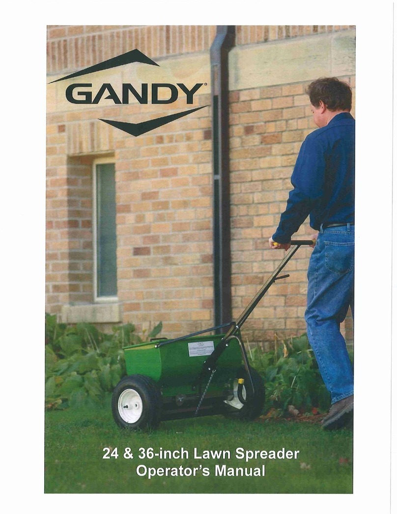
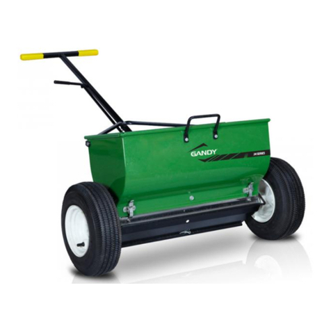
Gandy 36H12 User manual


~ 1 ~
Turf Tender®
Gandy 24” & 36” Spreader Overview
Your Operator’s Manual:
Use and care for your Gandy Turf Tender Spreader.
Gandy Spreaders are rugged machines that deliver precision applications.
Model:____________________ Serial Number:____________________
General Maintenance & Use:
Check all hardware periodically for tightness.
Always empty hopper when finished. Never leave fertilizer, chemical or treated seed in the spreader.
These materials can corrode and rust the spreader.
Always follow all safety guidelines listed on the product label you are applying.
It is the responsibility of the user to follow all application rate guidelines for the product you are applying.
Specifications:
Model Numbers: (H = Push Models) (T = Tow Hitch):
All 24” Models (H & T): Spread width 24-inch wide.
All 36” Models (H & T): Spread Width 36-inch wide.
Hopper Capacity: (Based on Fertilizer Weighing 65 lbs. per Cu. Ft.)
All 24” Models (H & T): 1.2 Cu. Ft, Approximately 78 lbs.
All 36” Models (H & T): 1.8 Cu. Ft, Approximately 120 lbs.
Variable Rate Spreaders (Standard):
24 & 36-inch Model Gandy spreaders have removable variable rate stainless steel bottoms.
In the rate charts the term “Gauge Setting” refers to the numbers stamped on the Cam Gauge located on the
stainless steel bottom attached under the spreader.
For Fixed Rate Spreaders: (Special Order Only)
The term “Bottom Number” refers to the size of the various fixed-rate bottoms (painted black) available for fixed
rate spreaders only. These bottoms require special shut-off packages to work.
Fixed rate bottoms will not work on the standard variable rate spreaders without a conversion package.
These bottoms are not adjustable and are not recommended for chemical, seed or fertilizer applications.

~ 2~
Calibration / Application Instructions
1. Determine Push / Pull Speed of Application
Determine the speed at which you are going to push or pull the spreader.
The speed at which you travel has direct effect on the rate you apply.
Note: Average slow walking speed is about 2 to 2-1/2 miles per hour for reference.
Try to walk a fairly consistent speed each time.
When pulling the spreader with a lawn mower or small tractor that does not have a speedometer make sure
you use the same gear and throttle settings for each pass to control your application speed.
With the same cam gauge setting, the rate of application at one mile per hour is twice that at two miles per hour.
Example: If you calibrate for 2-1/2 mph but apply at 5 mph you will only apply half your desired application rate.
Likewise, if you calibrate for 5 mph but apply at 2-1/2 mph you will double your application rate.
Use chart below to determine your speed by distances traveled in one minute.
1 mph
2 mph
2-1/2
mph
3 mph
3-1/2
mph
4 mph
4-1/2
mph
5 mph
Traveled in 1 min.
88 Ft.
176 Ft.
220 Ft.
264 Ft.
308 Ft.
352 Ft.
396 Ft.
440 Ft.
2. Determine Rate of Application
See the product label on the bag of material you wish to apply to determine your rate of application,
safety guidelines for handling the material and any restrictions for applying.
Note: Most products are listed in pounds applied per 1,000 square feet.
3. Setting Cam Gauge
Refer to the rate charts supplied with your spreader for a suggested starting cam gauge setting.
If the desired material is not listed in the chart you will have to calibrate that material with the spreader.
Move cam gauge away from the stop (close bottom openings) before attempting adjustment.
Loosen wing nut and turn cam gauge to desired number, using the top surface of the stop as the
setting indicator and then tighten wing nut. See picture of cam gauge set at “65”.
For example, if the spreader is to be used with the bottom completely open, the
cam gauge would be turned until the graduating mark directly opposite the
number 80 is in line with the top edge of the stop.
Likewise, if the spreader were to be half open, the graduation mark opposite the
number 40 would be in line with the top edge of the stop.
Note: Numbers on the cam gauge DO NOT represent any application rate, they
are reference numbers only for setting repeatability.
You can “fine tune” the application rate with precision.
You can adjust the cam gauge so it is set in between the marks.
This opens the bottom half the distance as the full mark.
The fine adjustments are possible because the cam gauge is attached directly to the slide.
Remember the settings in the rate charts are only guide lines for beginning calibration.
Formulations (size of material) can vary from brands, batches and from year to year.
It is the responsibility of the operator to properly calibrate the spreader before applying any materials.
Caution: When applying high potency fertilizers that will burn, be sure to be moving when beginning application.
Check your results as outlined in Step 4 and make adjustments as necessary.

~ 3~
4. Check Rate
It is the responsibility of the operator to properly calibrate the spreader before applying any material.
Making a precision application is simply a matter of filling up the hopper, moving the lever so the cam gauge is
against the stop, walking or driving at your selected speed, and double checking your application rate.
It is important that you check your rate to see that the setting you have chosen from the charts are giving you the
results you want. Atmospheric conditions alone can affect the flow of materials.
Most rates are listed in pounds applied per 1,000 square feet.
Note: Always move the cam gauge away from the stop (bottom closed) before attempting to set the cam gauge.
Check your rates as follows:
With Optional Calibration Pan: (Part #28368584 for 36” Spreader or #28248584 for 24” Spreader)
24” Turf Tender Drop Spreader
•Attach optional Gandy calibration pan under spreader
•Fill spreader full
•Push or Pull spreader 50 feet
•Weigh the amount of material that was caught in the calibration pan
•Multiply that weight x 10 to get pounds of material applied per 1,000 square feet
36” Turf Tender Drop Spreader
•Attach optional Gandy calibration pan under spreader
•Fill spreader full
•Push or Pull spreader 50 feet
•Weigh the amount of material that was caught in the calibration pan
•Multiply that weight x 6.7 to get pounds of material applied per 1,000 square feet
42” Turf Tender Drop Spreader
•Attach optional Gandy calibration pan under spreader
•Fill spreader full
•Push or pull spreader 50 feet
•Weigh the amount of material that was caught in the calibration pan
•Multiply that weight x 5.7 to get pounds of material applied per 1,000 square feet
If necessary, adjust cam gauge up or down and check again.
Calibration: (Know Area)
It is recommended that when calibrating chemical or fertilizer to not apply directly to the ground.
Lay down a large tarp or drop cloth to collect all material to be reused after calibrating.
Make sure you have enough material to refill the spreader.
•Fill the spreader level full
•Weigh the bag of material (remaining amount of material left in bag) and write that down
•Treat a known area, such as 1,000 square feet.
•Refill spreader level full (same level as last fill)
•Weigh the remaining bag of material (remaining amount of material left in bag) and write that down
•Subtract the left over weight from the starting weight, this is what you applied in pounds per 1,000 square feet
If necessary, adjust cam gauge up or down and check again.
You can check on smaller areas, such as 500 sq. ft. or 250 sq. ft., using 1/2 or 1/4 of the rate per 1,000 sq. ft.

~4~
Maintenance & Cleaning For Gandy 24” & 36” Turf Tender®
General Maintenance:
Check all bolts for tightness periodically.
Always empty hopper when finished.
Never leave fertilizer, chemical or treated seed in the spreader.
These materials can corrode and/or rust the spreader.
Cleaning:
Always follow all safety guide lines listed on the product label of material used in spreader when cleaning.
Untreated Seed: No coating (chemical / fertilizer) on seed.
If spreader is only used for seeding untreated seed and the shut-off lever moves freely all that is needed to do
is wipe out or rinse out the seed dust and let the spreader dry before using again.
Chemical, Fertilizer or Treated Seed: It is recommended to do a more thorough cleaning.
(For detailed drawings see Parts & Assembly Manual that was supplied with spreader)
1. With spreader empty turn spreader over so the bottom faces up.
2. Remove both tires.
3. Remove the spread plate by removing the wing nuts and washers holding the bearing retainers in place.
4. With the spread plate and bearing retainers removed, un-snap and un-hook the latches holding the
stainless bottom in place.
Note: There are 6 latches (3 each side) on the 36” spreader and 4 latches (2 each side) on the 24” spreader.
With the latches un-hooked, grab the bottom on one end and pull straight up to remove the bottom.
5. Remove the bearings, rotor bars and end washers (on ends of rotor bar) from the spreader.
6. Wipe & clean all parts including spreader hopper. Clean all material out of the center and end bearings.
Note: See Bottom Disassembly instruction on Page #5.
7. After cleaning the bearings, place a few drops of light oil on the inside of each bearing.
Note: The bearings are porous and will absorb small amounts of oil.
Note: The center and end bearings do not turn. The shaft turns inside the bearing.
Some materials have fine powder in the mixture, so it may be necessary to oil the bearings more often to
prevent powder from working into the bearings.
All parts need to be completely dry before reassembling.
8. Install end washers back on long ends of rotor bars. Reassemble rotor bars and bearings back on spreader.
9. Reinstall and center the stainless bottom on the spreader making sure the cam gauge is on the
handle/hitch side and the shut-off lever is in the U-notch.
Hook all the latches back onto the bottom and snap into place.
10. Reinstall tires.
11. Turn spreader upright on it tires and reconnect spread plate chain.
12. Open and close shut-off lever. If shut-off lever operates hard the bottom can be adjusted to operate easier.
(Similarly to Step #6 in the bottom disassembly instructions)
From the side opposite the cam gauge loosen the 3/6” flange nuts. Un-snap the latches on this side only
and tap the rear hanger to your right about 1/16” inch. Retighten 3/16” nuts, re-snap latches and try shut-
off lever again. Repeat if needed until shut-off lever operates smoothly.

~5~
Bottom Disassembly Instructions:
Occasionally it will be necessary to disassemble the stainless bottom for cleaning.
Some materials will build up in between the slide and the bottom especially when atmospheric humidity is high.
1. Remove the 5/16”wing nut, washer and cam gauge from bottom assembly.
Diagram A
OPP-36-24-A1
2. Measure the distance from the edge of the bottom to the edge of the rear hanger and write that down.
See Diagram B. You will use this dimension to reassemble the bottom.
Diagram B
OPP-36-24-A1
3. Remove the 3/16”flange nuts and nylon washers from the rear hanger.
Note: The 36” bottom has 4 nuts and washers. The 24” bottom has 2.
Diagram C
OPP-36-24-A1

~6~
4. With the nuts and washers removed you will see the angled slots on the rear hanger.
With a small hammer gently tap on the end of the rear hanger as shown to loosen it from the studs.
See Diagram D.
With the hanger loose, slide it in the direction shown until the threaded studs align with the straight up and
down area of the slot. See Diagram E.
Pivot the rear hanger away from the bottom and all the way off the studs.
This will allow the hanger to un-hook from the slide and be removed. See Diagram F.
Lift up and pivot the slide away from the bottom.
This will allow the side to unhook from the front hanger. See Diagram G.
Note: Be careful when handling the bottom & slide so you do not drop, bend, or dent it.
Diagram D
Diagram E
Diagram F
Diagram G
OPP-36-24-A1
*For compete assembly instructions see the Parts & Assemble Manual that was supplied with the spreader.

~7~
5. Note: Be careful when handling the bottom & slide so you do not drop, bend, or dent it.
With the bottom & slide disassembled wipe or wash these parts clean.
If any rust or corrosion has formed on these parts it should be removed.
(Fine steel wool or a fine scotch-bright pad & WD40 or similar products will work.)
Make sure all parts are dry and all oil removed before reassembling.
Do not oil or grease the bottom & slide. This will cause material to collect or stick in between the bottom &
slide and cause it to slide harder and/or bind up.
6. Bottom reassembly.
Hook slide to the front hanger as shown in Diagram H and pivot onto bottom.
Hook rear hanger under lip of slide. Align the studs with straight up and down area of the slots on rear
hanger and pivot into the bottom as shown in Diagram J.
With a small hammer gently tap on the end of the rear hanger as shown until the rear hanger matches the
dimension you took from Step #4, Diagram D. See Diagram K.
Reinstall the nylon washers and 3/16” flange nuts to all studs. Be careful when tightening flange nut as to
not over tighten and twist off.
Note: You should be able to move the slide by hand. If you cannot move the slide by hand loosen the
3/16” flange nuts and slightly tap the rear hanger the opposite direction as shown in Diagram K, tighten
the 3/16” nuts and try to slide by hand again. Repeat this process if needed.
Reinstall the cam gauge, washer & wing nut.
Reassemble bottom on spreader.
Diagram H
Diagram J
Diagram K
OPP-36-24-A1

~ 8~
Optional Extra Equipment: (Ordered Separately)
Calibration Pans:
Calibration pan hangs under the spreader to catch
material for weighing to check application rates.
Jigglers Packages:
Use with materials that bridge.
When installed, Jigglers contact the rotor bar and
move up and down to help maintain an even flow.
Part Number for 24” Spreader: 28248584
Part Number for 36” Spreader: 28368584
Part Number for 24” Spreader: J24
Part Number for 36” Spreader: J36
28248584
J36
Limited Warranty
The Gandy Company warrants all material and workmanship on Gandy equipment delivered to be free
of defects for a period of 12 months from date of original purchase. Products used on a commercial, rental or
leased basis are warranted for 90 days. Any part or parts thought to be defective within these warranty periods
are to be returned through your servicing dealer or distributor to the Gandy Company's plant. Distributor or
dealer must receive authorization from Gandy Company to return items under warranty. An authorization
number will be issued and must be clearly visible on all packages returned to the factory. If found defective by
Gandy Company, replacement parts will be forwarded free of charge, prepaid. No service, labor charge or
expense on the equipment will be allowed unless such expense has been previously authorized in writing by
the Gandy Company. Serial number and model of the unit involved is required by the Gandy Company on all
warranty claims. Gandy Company policy is to improve products whenever it is practical to do so. It reserves the
right to make changes or add improvements at any time without incurring any obligation to make such changes
on products sold previously. This warranty does not apply to products altered or misused by users after the point
of manufacture.
This warranty against defects in material and workmanship is in lieu of all other warranties, expressed or
implied, and there are no other warranties of any kind whatsoever including, but not limited to, any
implied warranty of merchantability or fitness for any particular purpose. In no event shall the company
be liable for any incidental or consequential damages whether for breach of warranty, for breach or
repudiation of any other term or condition hereof, or for negligence, on the basis of strict liability, or for any
other reason.
Gandy Company
815 Rice Lake Street
Owatonna, MN 55060
Website: www.gandy.net
Form 2436OM808-IP
This manual suits for next models
3
Table of contents
Other Gandy Spreader manuals
Popular Spreader manuals by other brands

Glasdon
Glasdon ICEMASTER 50 Instruction leaflet

JEANTIL
JEANTIL EPR Series instruction manual

Tatu Marchesan
Tatu Marchesan DCA2 MC 2500 Operator's manual

Dalton
Dalton Mobility 100 Operating and parts manual

Ferris
Ferris Voyager FS5250 Series Operator's manual

Amazone
Amazone ZG-B 5500 Ultra Hydro operating manual

Krampouz
Krampouz Easy Crep System Instructions for use

PermaGreen Supreme
PermaGreen Supreme MAGNUM SmartSteer C3C 2009 Operator's manual

Oypla GARDEN
Oypla GARDEN 4306 user manual

Kramer
Kramer VM-4DVI-R user manual

Fisher
Fisher Speed-Caster owner's manual

Art's-Way Manufacturing
Art's-Way Manufacturing X900 Operator manual & illustrated parts list