Gardena 4000/4 1482 User manual

GARDENA
®
DGebrauchsanweisung
Hauswasserautomat
GB Operating Instructions
Pressure Tank Unit
FMode d’emploi
Pompe d’arrosage automatique
NL Gebruiksaanwijzing
Pomp met hydrofoor
SBruksanvisning
Pumpautomat
IIstruzioni per l’uso
Pompa ad intervento automatico per uso domestico
EManual de instrucciones
Bomba doméstico
PInstruções de utilização
Bomba de Pressão
DK Brugsanvisning
Husvandværk
4000/4 electronic plus
Art. 1482
4000/5 electronic plus
Art. 1484

E
B
3
G
5
C
4
2
13
D
C
9
0A
D
D
EF
5
6D
7
F
8
B
3
13a
A
0 1000 2000 3000 4000 l/h
m
50
40
30
20
10
0
bar
5
4
3
2
1
4000/5 electronic plus
4000/4 electronic plus
F1
F6
F2
F7
F3
F8
F4
F9
F5

4
DBitte lesen Sie diese
Gebrauchsanweisung vor
Montage und Inbetriebnahme Ihres
Gerätes sorgfältig. Beim Lesen
der Gebrauchsanweisung bitte
die Umschlagseite herausklappen.
Inhaltsverzeichnis Seite
1. Hinweise zur Gebrauchs-
anweisung 5
2. Ordnungsgemäßer Gebrauch 5
3. Technische Daten 5
4. Funktionsteile 6
5. Maßnahmen vor der
Inbetriebnahme 6
6. Inbetriebnahme 7
7. Sicherheitshinweise zur
Inbetriebnahme 7
8. Funktion und Display des
Elektronischen Druckschalters 8
9. Benutzungshinweise 9
10. Wartung, Pflege, Aufbewahrung 9
11. Empfehlenswertes Zubehör 10
12. Störungen 10
Garantie 74
GPlease read these operating
instructions carefully before
assembling and using the unit.
Unfold inside cover pages to read
the operating instructions.
Contents Page
1. Information concerning
the Operating Instructions 14
2. Product Use 14
3. Technical Data 14
4. Functional Parts 15
5. Preparations prior to Operation 15
6. Starting Operation 16
7. Safety Hints before Operation 16
8. Function and Display of the
Electronic Manometric Switch 17
9. Operation Hints 18
10. Maintenance, Care, Storage 18
11. Recommended Accessories 19
12. Trouble-Shooting 19
Guarantee 74
FNous vous remercions de bien
vouloir lire attentivement ce
mode d’emploi avant d’utiliser votre
pompe. Pour une meilleure com-
préhension, dépliez le 2ème volet
de la couverture de manière à faire
apparaître les schémas de montage.
Contenu Page
1. Informations sur le mode
d’emploi 22
2. Domaine d’utilisation 22
3. Caractéristiques techniques 22
4. Description du produit 23
5. Préparation de la mise en service 23
6. Mise en service 24
7. Précautions d’emploi 24
8. Fonctionnement et affichage
de l’interrupteur manométrique 25
9. Conseils d’utilisation 26
10. Entretien et rangement 27
11. Accessoires recommandés 27
12. Incidents 27
Garantie 74
NLees deze gebruiksaanwijzing
voor montage en ingebruik-
name van het apparaat zorgvuldig
door. Bij het lezen van de gebruiks-
aanwijzing de bladzijden met de af-
beeldingen openslaan.
Inhoudsopgave Pagina
1. Aanwijzingen bij de
gebruiksaanwijzing 30
2. Juist gebruik 30
3. Technische gegevens 30
4. Bedieningsonderdelen 31
5. Maatregelen vóór de
ingebruikname 31
6. Ingebruikname 32
7. Veiligheidstips voor ingebruik-
name 32
8. Funktie en display van
de elektronische besturing 33
9. Gebruikstips 34
10. Verzorging, onderhoud, opslag 34
11. Aanbevolen accessoires 35
12. Storingen 35
Garantie 74
SLäs igenom bruksanvsiningen
noggrant innan Du tar Din
pump i bruk. Ha omslaget utvikt när
Du läser bruksanvisningen.
Innehåll Sida
1. Information 38
2. Användningsområde 38
3. Tekniska data 38
4. Beskrivning 38
5. Åtgärder innan automaten
tas i bruk 39
6. Drift 40
7. Säkerhetsråd vid drift 40
8. Den elektroniska styrningens
funktion och display 40
9. Viktiga råd 42
10. Underhåll, skötsel och förvaring 42
11. Rekommenderade tillbehör 42
12. Felsökning 42
Garanti 75
IPrima di mettere in uso la
nuova pompa, leggere attenta-
mente le istruzioni tenendo aperto
il pieghevole per avere sott’occhio
i disegni esplicativi.
Indice pagina
1. Avvertenze 45
2. Uso corretto 45
3. Caratteristiche tecniche 45
4. Parti funzionali 45
5. Operazioni preliminari 46
6. Messa in uso 47
7. Norme di sicurezza 47
8. Pressostato elettronico 47
9. Norme operative 48
10. Manutenzione 49
11. Accessori 49
12. Anomalie di funzionamento 49
Garanzia 75
EAntes del montaje y de la
puesta en marcha del aparato,
aconsejamos una atenta lectura del
presente manual de instrucciones.
Para facilitar la lectura, desdoble la
cubierta.
Índice Página
1. Indicaciones del manual
de instrucciones 52
2. Uso correcto 52
3. Datos técnicos de la bomba 52
4. Piezas funcionales 52
5. Operaciones antes de la puesta
en servicio 53
6. Puesta en servicio 54
7. Medidas de seguridad para
la puesta en funcionamiento 54
8. Función y display del interruptor
electrónico 54
9. Instrucciones de uso 56
10. Mantenimiento, cuidados,
almacenamiento 56
11. Accesorios recomendados 56
12. Averías 57
Garantía 75
PPor favor leia atentamente
estas instruções de utilização
antes de utilizar esta bomba.
Desdobre as páginas na capa interior
para ler as instruções de utilização.
Conteúdo Página
1. Informações acerca das
instruções 59
2. Utilização do produto 59
3. Dados técnicos 59
4. Componentes funcionais 60
5. Providências a serem tomadas
antes da colocação em funcio-
namento 60
6. Colocação em funcionamento 61
7. Medidas de segurança antes
do funcionamento 61
8. Funcionamento e indicações
do display do interruptor
manométrico electrónico 62
9. Conselhos de utilização 63
10. Manutenção, conservação
e armazenagem 64
11. Acessórios recomendados 64
12. Falhas 65
Garantia 75
KLæs denne brugsanvisning
omhyggeligt igennem før mon-
tering og igangsætning af apparatet.
Klap brugsanvisningens omslagsside
ud under læsningen.
Inhold Side
1. Henvisninger til brugsanvisningen 67
2. Korrekt anvendelse 67
3. Tekniske data 67
4. Funktionsdele 67
5. Foranstaltninger før igangsætning 68
6. Igangsætning 69
7. Sikkerhedshenvisninger
i forbindelse med igangsætning 69
8. Det elektroniske manometer
kontakts funktion og display 69
9. Anvendelseshenvisninger 71
10. Vedligeholdelse, pleje, opbevaring 71
11. Anbefalelsesværdigt tilbehør 71
12. Fejl 72
Garanti 75

15
G
14
G
1Water drain screw
2Suction side
3Pump fitting 33.3 mm (G1)
4Filler cap with screw plug
5Electronic Manometric Switch
6Inlet, delivery side
7RESET button
8Light-emitting diodes
9Screws for casing attachment
0Casing cover
ATurbine
BTurbine axle
CRotary switch for non-return
valve
DMains connector for the
Manometric Switch
EConnector socket for
pump connector plug
FMains plug for pump
GOutlet, delivery side
4. Functional Parts (ill. B/C/E)
5.1 Mounting the Electronic
Manometric Switch
The Electronic Manometric Switch
5is fitted with a 33.3 mm (G1)
outer thread at the inlet side 6.
To mount the Electronic Mano-
metric Switch proceed as follows:
1. Hold the top of the Electronic
Manometric Switch with one
hand and with the other, screw
the lower rotating part into the
inner thread of the pump.
Screw up to the limit.
Note: When the limit has been
reached, the non-return valve
(13a) can be turned in the
counter-clockwise direction
– a maximum of one turn
however – into any position
which is the most convenient
for you. The display can also be
turned into any desired position
before the connection on the
pressure side 3/ Gis tight-
ened up.
2. Plug the mains plug for the
pump Finto the connector
socket Eat the back of the
display for the Electronic
Manometric Switch (ill. E).
5.2 Location and Filling of
the Pump before Operation
1. Locate the pump at safe
distance of the liquid.
Take care that the site is firm
and solid, in order to ensure
safe location of the pump.
2. Before operation, fill the
pump either a) through the
filler cap, or b) through the
outlet nozzle of the Elec-
tronic Manometric Switch
with at least 2 I of the liquid
to be pumped:
a) To fill the pump through
the filler cap 4: Undo the
screw plug at the filling
nozzle and tighten up again
after filling the pump (do
not use a wrench).
b) To fill the pump through the
outlet nozzle on the delivery
side Gof the Electronic
Manometric Switch:
1. Set the rotary switch/ non-
return valve to position 2
(non-return valve open).
2. Open the screw plug
of the filler cap 4(for
bleeding).
3. Fill the pump with liquid
through the outlet on the
delivery side Gof the
Electronic Manometric
Switch until liquid exits
the pump on the suction
side 2.
4. Tightly close the screw
plug again.
As well as the pump itself,
the suction hose with back-
flow preventer shall be filled
in order to ensure trouble-
free drawing (refer to the
section “Suction hose con-
nection”).
5.3 Suction hose connection
Suction Side 2
1. Screw one of the two supplied
pump fittings 3onto the
suction side 2of the pump
and tighten it by hand until
the washer fits closely.
Note: For the suction side use
a vacuum-resistant suction
hose with back-flow pre-
venter (e.g. GARDENA Suc
tion Unit, art.no. 1411). Only
this way, the suction hose can
be filled up before initial opera-
tion. Additionally, the liquid to
be pumped stays in the suction
hose, when the pump cuts
out. Thus easy priming is
made possible when starting
the pump again. For suction
heights exceeding 4 m, we
recommend to fix additionally
the suction hose, e.g. by fas-
tening it to a wooden peg, thus
the pump is relieved of load.
2. Before connection, equip the
union nut of the suction hose
with the supplied dirt filter (ill.
D). First of all remove the flat
packing which may be in the
union nut.
Note: Alternatively, you can
also use the GARDENA Pump
Preliminary Filter, art. no. 1730/
1731. It is especially recom-
mended for use with highly
contaminated or with a very
sandy liquid. Filtration of water
is essential to prevent the Elec-
tronic Manometric Switch from
internal contamination, thus
avoiding malfunction of the unit.
3. In case of permanent, indoor
installation of the pump for
domestic water supply, in order
to reduce noise and to avoid
damages at the Manometric
Switch caused by vibration,
it is recommended to connect
the Pressure Tank Unit via
flexible suction lines, e.g. in
conjunction with the GARDENA
Bore Hole Suction Hose,
art.no. 1729, to the pipe net-
work but not firmly via rigid
pipes.
5. Preparations prior to Operation
Please read these operating
instructions thoroughly. Follow
the information given. Use the
operating instructions to get
acquainted with the operating
parts and the proper use of
the Pressure Tank Unit.
AFor safety reasons,
people who are not
familiar with these operating
instructions should not use
this Pressure Tank Unit.
Following the operating instruc-
tions supplied by the manufac-
turer is a prerequisite for the
proper use of the pump.
The operating instructions include
all necessary instructions con-
cerning operation, maintenance
and service.
GARDENA Pressure Tank Units
4000/4 electronic plus, 4000/5 electronic plus
1. Information concerning the Operating Instructions
GARDENA Pressure Tank Units
have been designed for private
use around house and garden.
Pressure Tank Units are pre-
dominantly used for operating
watering implements and systems
in private gardens.
Besides, the GARDENA Pres-
sure Tank Units can be used for
domestic water supply, e.g. when
taking rainwater for domestic
use.
AGARDENA Pressure Tank
Units are not designed for
continuous operation (e.g. in-
dustrial application, continuous
circulating operation).
Corrosive, easily combustible,
aggressive or explosive sub-
stances (e.g. petrol, petroleum,
nitro thinner) as well as food
must not be pumped.
The temperature of the liquid to
be pumped should not exceed
35 °C.
2. Product Use
4000/4e plus 4000/5e plus
Rated power 800 W 1,000 W
Max. delivery capacity 3,600 l/h 3,600 l/h
Max. delivery head 42 m 50 m
Max. pressure
(= cut-out pressure) 4.2 bar 5.0 bar
Cut-in pressure approx. 2.2 ± 0,2 bar 2.2 ± 0,2 bar
Max. suction head 9 m 9 m
Perm. internal pressure
(delivery side) 6 bar 6 bar
Voltage 230 V 230 V
Frequency 50 Hz 50 Hz
Noise level LWA 1) 77 dB (A) 79 dB (A)
1) Measuring method according to directive 2000/14/EC
Performance Characteristics (ill. A)
Technical data of the above performance characteristics is measured at a suction height of 0.5 m,
using a 25 mm (1”) suction hose.
3.Technical Data

17
G
16
G
The Electronic Manometric Switch
is equipped with an electronic
control unit with fixed programs.
The electronic control unit is acti-
vated by pulses from the mano-
metric switch and the flow recog-
nition of the dry-running safety
feature.
The manometric switch is set
at the factory to a switching
pressure of approx. 2.2 bar.
This setting cannot be changed.
The dry-running safety mech-
anism protects the pump
against damage and controls
the time the pump continues to
run against the closed delivery
side.
The LEDs (light emitting diodes)
display the operating status
(➔see “Electronic Control Dis-
play”).
Explanation of Terms
..Priming cycle
The pump attempts to restore
normal operation in 4 minutes.
..Automatic self-priming mode
(➔➔yellow Alarm LED flash-
es)
After a fault, the pump’s elec-
tronic control unit makes three
automatic self-priming attempts
at different time intervals (after
1 hour, after 5 hours and after
20 hours) to restore normal
operation.
The priming cycle (see above)
is used for each of these at-
tempts.
..Re-plugging
(removing the mains plug
and then plugging it
back in the socket again)
Important ! Remove the plug
from the socket! Check the
unit and pump for any faults
(see section “Finding Faults”).
Rectify any faults and restart
the pump by plugging the
mains plug into a socket sup-
plying 230 V AC.
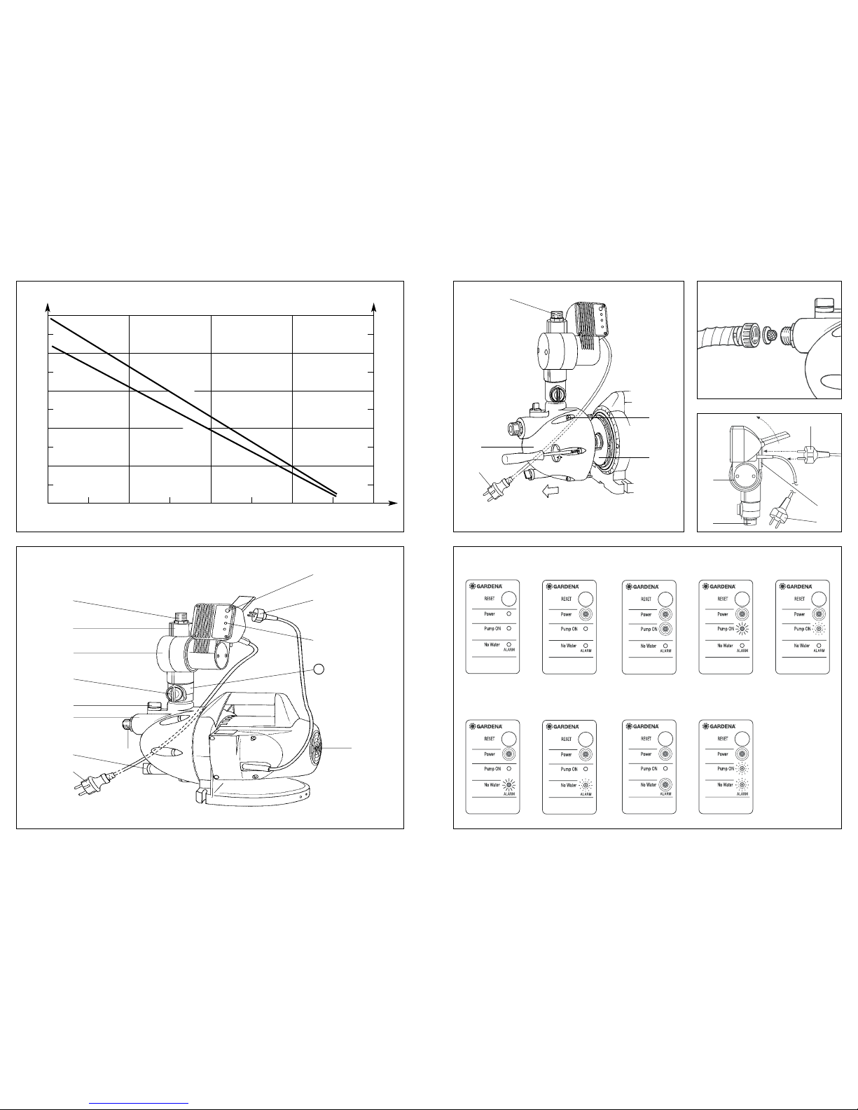
Electronic Control Display
Operating Status
lit flashing flashing
quickly
..RESET Button (ill. F 1)
The RESET button is used
to reset and restart the pump
after a fault.
..Red Power LED is lit (ill. F 2)
The pump is connected to
the mains power.
The pump functions in the
normal operating mode.
..Green LED is lit (ill. F 3)
The pump is connected to the
mains and the pump is running.
Once the pump has reached
the max. pump pressure, the
pump switches off (the green
LED extinguishes) and the
pump functions in the normal
operating mode.
..Green LED flashing slowly
(once a second) (ill. F 4)
➔The flow rate on the deliv-
ery side is too low (below
90 l/h).
The pump continues to run
and then switches off. It
turns on again as soon as
the switching pressure of
approx. 2.2 bar has been
reached (e.g. in the case
of a leak).
➔The pump must be switched
off just before you finish
draining water from the unit.
..Green LED flashing quickly
(four times a second) (ill. F5)
➔The flow rate on the inlet
side is too low (below
400 l/h).
The pump continues to
run for approx. 40 seconds.
If normal operation is not
achieved during this time,
the pump switches off and
the control unit changes
to the “automatic self-
priming mode”.
Note: The pump can be
switched on again at any
time by pressing the
RESET button.
..Yellow LED flashing slowly
(once a second) (ill. F 6)
➔The amount of water is
too low when restarting
the pump.
The pump runs through
the first “priming cycle”.
If the normal operating
mode is not achieved, the
pump switches off and
the control unit changes
to the “automatic self-
priming mode”.
Note: The pump can be
restarted at any time by
pressing the RESET button.
..Yellow LED flashing quickly
(four times a second) (ill. F7)
➔Alarm which indicates if the
amount of water is too low
when the pump is operating
in the normal mode. The
control unit changes to the
“automatic self-priming
mode”.
Note: The pump can be
restarted at any time by
pressing the RESET button.
..Yellow LED is lit (ill. F 8)
➔The “automatic self-
priming mode” is no longer
active and the unit is no
longer supplying water
(e.g. no water in the con-
tainer or borse or the filter
is dirty).
Note: The pump can be
restarted at any time by
pressing the RESET button
or by “re-plugging”.
..Green and yellow LEDs
flashing quickly and alter-
nately
(four times a second) (ill. F9)
➔Warning: There is a leak
in the pipe system.
8. Function and Display of the Electronic Manometric Switch
Important! Don’t use any hose
connection system fittings on
the suction side!
Delivery Side G
4. Screw the second pump fitting
3into the outlet nozzle of the
delivery side Gof Electronic
Manometric Switch, and tighten
up by hand. Take care that the
washer of the pump fitting fits
closely to the delivery side.
Note 1: The pump fitting is
equipped with a 33.3 mm (G 1)
thread to which 13 mm (1/2”),
19 mm (3/4 ”) and 16 mm
(5/8”) hoses can be connect-
ed by using GARDENA hose
connection system fittings.
Note 2: Best results regarding
the delivery capacity of the
pump are achieved when con-
necting 19 mm (3/4 ”) hoses
in conjunction with GARDENA
“Profi” Maxi-Flow System fit-
tings (e.g. art.no. 1752) or
when using 25 mm (1”) hoses
with fittings available from
your sanitary dealer.
When connecting simultane-
ously several hoses / watering
accessories, we recommend
application of our GARDENA
Twin-Tap Connector (art.no. 1210)
or Four Channel Water Distributor
(art.no. 1194) which can be
screwed directly onto the pump
fitting on the delivery side G.
Using the pump for the
first time
1.Set the switch of the backflow
valve to Position 2.
2.Slightly open the release
points in the delivery pipe (e.g.
spray lance, tap) ➔air must
be allowed to escape during
the suction process.
3.Plug the mains plug Dfor the
Electronic Manometric Switch
into an outlet socket supplying
230 V alternating current.
Caution! The pump immedi-
ately starts to run!
4.As soon as the pump begins
to pump, turn the switch to
Position 1 (normal operation)
➔ensures fault-free operation
of the pump.
6. Starting Operation
A..Caution: Pursuant to
DIN VDE 0100-702 and
0100-738 use of the pump
nearby swimming pools and
garden ponds and other
similar places is only permis-
sible, if the pump is operated
with a residual-current de-
vice with a residual-current
rating ≤≤30 mA. Please ask
your electrician for his ad-
vice.
..The pump must be located
on solid, even ground, pro-
tected from flooding.Take
care that the pump cannot
fall into water.
..Mains power cables should
not have a smaller cross-
section than a rubber
sheathed cable of the desig-
nation H07 RNF. Extension
cables must meet the re-
quirements of DIN VDE 0620.
..In Austria, the electrical
connections must be made
according to ÖVE-EM 42,
T2 (2000)/1979 § 22 based
on § 2022.1. Pursuant to this
regulation it’s imperative to
operate pumps for swimming
pools and garden ponds
exclusively via an isolating
transformer. Please ask
your electrician.
..In Switzerland mobile appli-
ances which are used out-
doors, must be connected
via a residual-current device.
..When using the pump for
domestic water supply,
please adhere to the local
water and sewerage regula-
tions. In addition observe
the regulations of DIN 1988.
If necessary, contact your
sanitary expert.
..Children under the age of 16
are not allowed to operate
the pump. Keep them away
from the connected unit.
..Protect the pump from rain.
Don’t use the pump in wet
or moist area.
..Before operating the pump,
first make a visual check, if
there is any damage of the
pump (esp. regarding power
cable and plug). A damaged
pump must not be used. In
case of damage, please have
the pump checked by our
GARDENA Service Centre or
by an authorised electrician.
..Check line voltage. Data
indicated on the type plate
must match technical data
of the mains supply.
7. Safety Hints before Operation
This manual suits for next models
5
Table of contents
Other Gardena Pressure Washer manuals